EP0644285B1 - Webmaschine mit einer Vorrichtung zum Positionieren einer Schussfadenschere - Google Patents
Webmaschine mit einer Vorrichtung zum Positionieren einer Schussfadenschere Download PDFInfo
- Publication number
- EP0644285B1 EP0644285B1 EP94870129A EP94870129A EP0644285B1 EP 0644285 B1 EP0644285 B1 EP 0644285B1 EP 94870129 A EP94870129 A EP 94870129A EP 94870129 A EP94870129 A EP 94870129A EP 0644285 B1 EP0644285 B1 EP 0644285B1
- Authority
- EP
- European Patent Office
- Prior art keywords
- sley
- holder
- bearing piece
- weaving loom
- rod system
- Prior art date
- Legal status (The legal status is an assumption and is not a legal conclusion. Google has not performed a legal analysis and makes no representation as to the accuracy of the status listed.)
- Expired - Lifetime
Links
- 238000009941 weaving Methods 0.000 title claims description 21
- 230000008878 coupling Effects 0.000 claims description 16
- 238000010168 coupling process Methods 0.000 claims description 16
- 238000005859 coupling reaction Methods 0.000 claims description 16
- 235000014676 Phragmites communis Nutrition 0.000 description 17
- 239000002759 woven fabric Substances 0.000 description 4
- 238000010586 diagram Methods 0.000 description 2
- 238000004519 manufacturing process Methods 0.000 description 2
- 238000005452 bending Methods 0.000 description 1
- 230000015556 catabolic process Effects 0.000 description 1
- 239000000463 material Substances 0.000 description 1
- 230000001105 regulatory effect Effects 0.000 description 1
Images


Classifications
-
- D—TEXTILES; PAPER
- D03—WEAVING
- D03D—WOVEN FABRICS; METHODS OF WEAVING; LOOMS
- D03D49/00—Details or constructional features not specially adapted for looms of a particular type
- D03D49/70—Devices for cutting weft threads
Definitions
- This invention relates to a weaving loom provided with a device for positioning at least one weft cutter relative to a sley.
- Known weaving looms are provided with a sley which, as is known, carries out an oscillating movement along a path describing a circular arc.
- a weft cutter When a weft cutter is fixed directly on the sley of the weaving loom, said weft cutter describes the same path as the sley itself, in other words also in a circular arc. This means that when the sley reaches the open position, the tips of the weft cutters fixed directly thereon then lie just below the grippers, for presentation of the severed weft to the grippers.
- the weft cutter moves into a position which is much too high relative to the weft.
- the disadvantage of this is that the weft cutter is no longer capable of intercepting and severing the weft during said movement.
- a weaving loom provided with a device for positioning at least one weft cutter relative to the sley having a holder for carrying said weft cutter and a bearing piece for accommodating the holder.
- the object of the invention is to provide a solution to the abovementioned problems.
- a weaving loom as defined in Claim 1 whereby the holder is slidably mounted inside the bearing piece so that it slides in a specific direction, thereby allowing the weft cutter to carry out an upward and downward movement.
- the bearing piece comprises a body and a tubular guide element connected immovably thereto, said body forming the part which is fixed immovably to the sley.
- the holder comprises a further body and a projection part which is connected immovably thereto and is provided for sliding inside said guide element, the sliding direction being at right angles to the lengthwise direction of the sley.
- a multiple-rod system for adjusting the slide of the holder in the bearing piece while driving the movement of the sley.
- the multiple-rod system is coupled at its one end to a frame by means of further coupling elements, and is coupled at its other end to the slidable holder.
- a hinged connection is also provided between said two ends of the multiple-rod system, said connection pivoting about a coupling shaft which is supported on bearings in said at least one sley leg.
- Each weft cutter is thus expediently mounted on the holder, and the holder is slidable in the bearing piece.
- the bearing piece is fixed immovably on the sley in such a way that each weft cutter can carry out a to and fro movement in a specific direction.
- This to and fro movement is caused by the multiple-rod mechanism, which is driven by means of the sley movement by way of coupling elements.
- Said multiple-rod mechanism forms a balancing lever which is mounted on bearings in the reed lever.
- One side of the balancing lever is immovably connected to the frame of the weaving loom by means of a drive rod, and the other side of the balancing lever is coupled by means of a further drive rod to the slidable holder.
- the loom reed undergoes a movement in which the reed alternately assumes a higher vertical position, on the one hand, and a lower vertical position, on the other hand.
- a multiple-rod mechanism it is desirable in this case for the fell of the woven fabric ultimately to lie as close as possible to the reed, in order to keep the bending moment on the reed dents and on the reed as low as possible.
- the multiple-rod side of the reed movement is designed in such a way that the reed reaches its highest position in its so-called front, beating-up position and assumes a lower position in its so-called open, rear position. This ensures that warp threads form a downward oriented angle for the shed opening.
- said multiple-rod system consists of a four-rod mechanism containing a double pair, each pair having a connecting point in said coupling shaft, in which a respective lever engages and forms the connection with a respective drive rod, which drive rods in each case engage in said two ends of the four-rod system.
- said slidable holder and the bearing piece form a slide pair, and said bearing piece has a certain inclination or can also possibly be arranged substantially vertically.
- each weft cutter also has a front and rear component, resulting in that both a vertical and a horizontal positioning of said at least one weft cutter can be obtained.
- the slide pair is disposed substantially vertically. This means that each weft cutter can carry out a substantially vertical up and down movement, resulting in that a height positioning of each weft cutter can be obtained. Some space can be gained through the vertical arrangement.
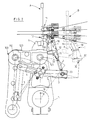
- Figure 1 is a schematic diagram of a positioning device with a loom reed according to the invention.
- Figure 2 shows a partial cross-section of the positioning device according to the invention, in the highest position or equilibrium position of the loom reed.
- Figure 3 is a diagram similar to that shown in Figure 2, in a lower or deflected position of the reed.
- Figure 1 shows a general perspective view of the part of a weaving loom in which a positioning device of two weft cutters 11, 12 according to the invention is accommodated.
- the weaving loom is provided with a sley 9, which carries out an alternating circular movement through a given angle ⁇ between a first, highest position A, as shown in Figure 2, and a second, open position B, as shown in Figure 3.
- the sley is moved by being driven by drive elements 100.
- the sley in this case has a set of elongated sley legs 5, which are disposed at a certain distance from each other and serve as coupling elements between the sley and the sley shaft 110 disposed parallel thereto.
- the sley shaft is supported in bearing blocks 111 on the frame 107 of the weaving loom and acts as a rotary shaft for the sley by way of the sley legs 5.
- Each sley leg 5 is in this case rotatably connected at its one end to the sley shaft and at its other end to the sley itself by means of a coupling piece 120 by way of a coupling shaft 105.
- each sley leg 5 is advantageously interrupted in such a way that said one end consists of two arms turned towards each other, in which the tension relative to the sley shaft can be regulated in a suitable manner by means of a tensioning nut 121.
- the coupling piece 120 is a part of said drive element 100 which is subjected to a movement under the influence of a rotary drive rod, to which it is rotatably connected by means of a shaft 112 supported on bearings therein.
- the coupling piece 120 has on its sley side a projecting profile which is suitably provided in a longitudinally profiled recess 130 on the underside of the sley.
- Each sley leg 5 is driven individually by one corresponding drive element 100, as can be seen from Figure 1.
- the holder 1 is slidably disposed in a bearing piece 30, which in turn is fixed laterally to the sley 9. More particularly, the bearing piece 30 consists of an element 31 fixed to the sley 9 and a guide element 32, e.g. tubular, which is immovably connected to the element 31.
- the holder 1 comprises a bearing plate 18, which serves as a support for the two weft cutters 11, 12, and a projecting part 19 opposite it which is provided for sliding into said tubular guide element of the bearing piece 30, in particular in a direction which is crosswise to the lengthwise direction of the sley 9, which is indicated by arrow F in the figures.
- the two weft cutters 11, 12 can make a to and fro movement relative to the sley in a particular direction.
- said to and fro movement of the two weft cutters 11, 12 is virtually vertical, in such a way that a height positioning of the weft cutters is thereby achieved.
- said slide pair 1, 30 can advantageously be given a certain angle of inclination, in such a way that herewith the weft cutters 11, 12 also have a forward and backward movement component.
- This embodiment ensures that there can be both vertical and horizontal positioning of the weft cutters 11, 12 relative to the sley.
- a multiple-rod system is provided according to the invention.
- the drive of the rod mechanism is produced by the movement of the sley itself.
- Said multiple-rod system consists of a balancing lever which is supported on bearings in the reed lever or sley leg 5 by means of a shaft 4.
- One side of the balancing lever is rotatably coupled to the frame by means of a first drive rod 7, which is immovably connected to a shaft 8 at its one end.
- the shaft 8 is supported in bearing blocks 16 on the frame 17.
- At its other end said first drive rod 7 is connected to a lever 6, which is connected directly to the shaft 4.
- a further lever 3 is also fixed at one end to said shaft 4 and is connected at the opposite end to a second drive rod 2 by way of an intermediate shaft 23.
- the other side of the balance is thus coupled to the slidable holder 1 by way of said second drive rod 2. This means that the slidable holder 1 can be held in a certain position relative to the sley by said second drive rod 2.
- a to and fro rotary movement of the reed lever 5 about the shaft 110 consequently produces the necessary up and down movement of the weft cutters 11, 12.
- the inclination of the slide pair 1, 30 can also be selected in such a way that the weft cutters 11, 12 slide backwards relative to the loom reed in the beating-up position and slide forwards relative to the reed in the open position, so that the tips of the weft cutter can pass the weft 50 better to the gripper and in front of the reed block.
- the abovementioned multiple-rod system can also be driven by means of a cam element 60, which is provided on the frame, and said cam element in this case is rotatably connected to the frame.
Landscapes
- Engineering & Computer Science (AREA)
- Textile Engineering (AREA)
- Looms (AREA)
Claims (8)
- Webmaschine versehen mit einer Vorrichtung zum Positionieren von wenigstens einer Schussfadenschere, gehörend zu einer Lade einer Webmaschine, in eine spezifische Richtung, mit einer Halterung (1) zur Aufnahme von wenigstens einer besagten Schussfadenschere (11, 12) und einem Trägerteil (30) zur Aufnahme der Halterung (1), welches Trägerteil unbeweglich auf der Lade befestigt ist, die wenigstens ein Ladenbein (5) hat, dessen erstes Ende mittels Kupplungselementen drehbar mit der Lade verbunden ist, dadurch gekennzeichnet, dass die Halterung (1) verschiebbar innerhalb des Trägerteils (30) montiert ist, so dass sie in eine spezifische Richtung (F) verschiebt.
- Webmaschine nach Anspruch 1, dadurch gekennzeichnet, dass das Trägerteil (30) einen Körper (31) umfasst und ein rohrförmiges, unbeweglich damit verbundenes Führungselement (32), wobei besagter Körper das Teil bildet, das unbeweglich an der Lade befestigt ist, und dadurch, dass die Halterung (1) einen weiteren Körper (18) aufweist und ein hervorspringendes Teil (19), das unbeweglich damit verbunden ist und vorgesehen ist um innerhalb des besagten Führungselements (32) zu verschieben, wobei die Verschiebungsrichtung (F) rechtwinklig auf die Längenrichtung der Lade (9) steht.
- Webmaschine nach irgendeinem der Ansprüche 1 oder 2, dadurch gekennzeichnet, dass ein Mehrfachgliedermechanismus vorgesehen ist zum Einstellen der Verschiebung der Halterung (1) im Trägerteil (30) während der Bewegung der Lade, wobei der Mehrfachgliedermechanismus mit seinem einen Ende mittels weiterer Kupplungselemente an ein Gestell (17) gekuppelt ist und mit seinem anderen Ende an die verschiebbare Halterung (1) gekuppelt ist, und wobei ebenfalls eine gelenkige Verbindung zwischen den beiden besagten Enden des Mehrfachgliedermechanismus vorgesehen ist, wobei besagte Verbindung um eine Kupplungswelle (4) dreht, die wenigstens in dem einen besagten Ladenbein (5) gelagert ist.
- Webmaschine nach Anspruch 1, dadurch gekennzeichnet, dass besagter Mehrfachgliedermechanismus besteht aus einem Vierstangenmechanismus, der ein Doppelpaar (2, 3; 6, 7) umfasst, wobei jedes Paar (2, 3) und (6, 7) jeweils einen Verbindungspunkt in besagter Kupplungswelle (4) besitzt, in den ein jeweiliger Hebel (3; 6) eingreift und die Verbindung mit einer jeweiligen Antriebsstange (2; 7) bildet, welche Antriebsstangen jeweils in die beiden besagten Enden des Mehrfachgliedermechanismus eingreifen.
- Webmaschine nach irgendeinem der Ansprüche 1 bis 4, dadurch gekennzeichnet, dass besagte Halterung (1) und besagtes Trägerteil (30) ein Gleitpaar bilden, und dass besagtes Trägerteil (30) wesentlich senkrecht angeordnet ist.
- Webmaschine nach irgendeinem der Ansprüche 1 bis 4, dadurch gekennzeichnet, dass besagte Halterung (1) und besagtes Trägerteil (30) ein Gleitpaar bilden, und dass besagtes Trägerteil (30) wesentlich senkrecht angeordnet ist.
- Webmaschine nach irgendeinem der Ansprüche 3 bis 5, dadurch gekennzeichnet, dass ein Nockenelement (60) auf dem Gestell (17) vorgesehen ist zum Antrieb des besagten Mehrfachgliedermechanismus, wobei besagtes Nockenelement (60) drehbar mit dem Gestell (17) verbunden ist.
- Positionierungsvorrichtung für wenigstens eine, zu einer Lade einer Webmaschine gehörende Schussfadenschere, in eine spezifische Richtung, die eine Halterung (1) zum Tragen von wenigstens einer besagten Schussfadenschere (11, 12) und ein Trägerteil (30) zur Aufnahme der Halterung (1) umfasst, welches Trägerteil unbeweglich auf der Lade befestigt ist, die wenigstens ein Ladenbein (5) hat, von dem ein erstes Ende mittels Kupplungselementen drehbar mit der Lade verbunden ist, dadurch gekennzeichnet, dass die Halterung (1) im Trägerteil (30) verschiebbar ist und dadurch, dass ein Mehrfachgliedermechanismus vorgesehen ist zum Einstellen der Verschiebung der Halterung (1) im Trägerteil während der Bewegung der Lade, wobei der Mehrfachgliedermechanismus mit seinem einen Ende mittels weiterer Kupplungselemente an ein Gestell (17) gekuppelt ist und mit seinem anderen Ende an die verschiebbare Halterung (1) gekuppelt ist, und wobei ebenfalls eine gelenkige Verbindung zwischen den beiden besagten Enden des Mehrfachgliedermechanismus vorgesehen ist, wobei besagte Verbindung um eine Kupplungswelle (4) dreht, die wenigstens in dem einen besagten Ladenbein (5) gelagert ist.
Applications Claiming Priority (2)
| Application Number | Priority Date | Filing Date | Title |
|---|---|---|---|
| BE9300792A BE1008211A5 (nl) | 1993-07-29 | 1993-07-29 | Inrichting voor het positioneren van een inslagschaar op een weefmachine. |
| BE9300792 | 1993-07-29 |
Publications (2)
| Publication Number | Publication Date |
|---|---|
| EP0644285A1 EP0644285A1 (de) | 1995-03-22 |
| EP0644285B1 true EP0644285B1 (de) | 1999-06-16 |
Family
ID=3887228
Family Applications (1)
| Application Number | Title | Priority Date | Filing Date |
|---|---|---|---|
| EP94870129A Expired - Lifetime EP0644285B1 (de) | 1993-07-29 | 1994-07-27 | Webmaschine mit einer Vorrichtung zum Positionieren einer Schussfadenschere |
Country Status (4)
| Country | Link |
|---|---|
| US (1) | US5568827A (de) |
| EP (1) | EP0644285B1 (de) |
| BE (1) | BE1008211A5 (de) |
| DE (1) | DE69419094T2 (de) |
Families Citing this family (9)
| Publication number | Priority date | Publication date | Assignee | Title |
|---|---|---|---|---|
| BE1014135A3 (nl) | 2001-04-20 | 2003-05-06 | Wiele Michel Van De Nv | Inrichting voor het aanreiken van inslagdraden op een grijperweefmachine. |
| CN101113548B (zh) * | 2007-08-29 | 2010-06-09 | 常州市润源经编机械有限公司 | 一种带有纬纱切割装置的缝编机 |
| EP2807299A4 (de) * | 2012-01-24 | 2015-07-15 | Nike Innovate Cv | Vorrichtung für webendbearbeitung |
| KR101954481B1 (ko) | 2012-01-24 | 2019-03-05 | 나이키 이노베이트 씨.브이. | 3차원 제직 시스템 |
| EP3456672B1 (de) | 2012-01-24 | 2021-07-07 | NIKE Innovate C.V. | Websystem umfassend einen intermittierenden webspleisser |
| BE1020551A3 (nl) * | 2012-03-01 | 2013-12-03 | Wiele Michel Van De Nv | Inrichting voor het losneembaar verbinden van elementen voor het positioneren van kettinggarens op een weefmachine. |
| WO2017134645A1 (en) * | 2016-02-05 | 2017-08-10 | Kurkute Sanjay | Oscillating sley mounted weft cutter for shuttle-less rapier weaving machines |
| CN109844197B (zh) * | 2016-09-14 | 2021-04-20 | 桑贾伊·库尔库特 | 用于无梭织机的纬纱夹持装置 |
| FR3132108B1 (fr) * | 2022-01-27 | 2024-01-26 | Staubli Sa Ets | Ensemble de formation de la foule pour un métier à tisser et son procédé de réglage |
Citations (2)
| Publication number | Priority date | Publication date | Assignee | Title |
|---|---|---|---|---|
| EP0104440A1 (de) * | 1982-09-02 | 1984-04-04 | N.V. Michel Van de Wiele | Schusssteuereinrichtung für Greiferwebmaschinen und Greiferwebmaschinen, die mit einer derartigen Schusssteuereinrichtung ausgerüstet sind |
| US4875507A (en) * | 1986-12-30 | 1989-10-24 | N.V. Michel Van De Wiele | Process and apparatus for guiding the weft threads in weaving looms |
Family Cites Families (5)
| Publication number | Priority date | Publication date | Assignee | Title |
|---|---|---|---|---|
| US3451440A (en) * | 1966-10-06 | 1969-06-24 | Ramon Balaguer Golobart | Cutting device for looms |
| ES343667A1 (es) * | 1967-07-13 | 1968-09-01 | Balaguer Golobart | Dispositivo de corte y aspiracion de los sobrantes latera- les de los hilos de trama en telares de trama fija. |
| US3596685A (en) * | 1968-07-06 | 1971-08-03 | Jose Bassa Bassart | Device for cutting and retaining the weft threads in shuttleless looms |
| CH554434A (de) * | 1973-06-20 | 1974-09-30 | Rueti Ag Maschf | Webmaschine mit einrichtungen zum eintragen der schussfaeden mittels eines fluidums. |
| ES193243Y (es) * | 1973-07-07 | 1975-01-16 | Incotex, S. A. | Mecanismo perfeccionado de corte, pinzado y presentacion detrama para telares. |
-
1993
- 1993-07-29 BE BE9300792A patent/BE1008211A5/nl not_active IP Right Cessation
-
1994
- 1994-07-27 EP EP94870129A patent/EP0644285B1/de not_active Expired - Lifetime
- 1994-07-27 DE DE69419094T patent/DE69419094T2/de not_active Expired - Lifetime
- 1994-09-27 US US08/312,793 patent/US5568827A/en not_active Expired - Fee Related
Patent Citations (2)
| Publication number | Priority date | Publication date | Assignee | Title |
|---|---|---|---|---|
| EP0104440A1 (de) * | 1982-09-02 | 1984-04-04 | N.V. Michel Van de Wiele | Schusssteuereinrichtung für Greiferwebmaschinen und Greiferwebmaschinen, die mit einer derartigen Schusssteuereinrichtung ausgerüstet sind |
| US4875507A (en) * | 1986-12-30 | 1989-10-24 | N.V. Michel Van De Wiele | Process and apparatus for guiding the weft threads in weaving looms |
Also Published As
| Publication number | Publication date |
|---|---|
| BE1008211A5 (nl) | 1996-02-13 |
| US5568827A (en) | 1996-10-29 |
| DE69419094T2 (de) | 1999-10-14 |
| DE69419094D1 (de) | 1999-07-22 |
| EP0644285A1 (de) | 1995-03-22 |
Similar Documents
| Publication | Publication Date | Title |
|---|---|---|
| EP0644285B1 (de) | Webmaschine mit einer Vorrichtung zum Positionieren einer Schussfadenschere | |
| US4614210A (en) | Leno device for weaving machines and weaving machines equipped with such a leno device | |
| US3952778A (en) | Selvage forming device | |
| US3717182A (en) | Rapier loom | |
| EP3425094B1 (de) | Schussfadenbetätigungsvorrichtung ohne falsche webkante in einer greiferwebmaschine | |
| EP1920094B1 (de) | Verfahren und vorrichtung zur herstellung eines drehergewebes auf einer webmaschine | |
| EP1899515B1 (de) | Frotteewebstuhl | |
| US5419375A (en) | Independently driven selvedge forming leno weaving device | |
| US4108214A (en) | Weaving loom with tension adjustor for warp edge threads | |
| US7225838B2 (en) | Method for producing a fabric in plain weaves and leno weaves and a loom for carrying out the method | |
| US5394905A (en) | Leno heald subassembly for cooperation with a main harness frame | |
| US3047027A (en) | Device for selvedge forming | |
| US4489761A (en) | Hand weaving loom | |
| US3171443A (en) | Selvage forming mechanism | |
| US6260586B1 (en) | Rail mounted weft cutting device with blade carrying arms | |
| KR0141647B1 (ko) | 더블 파일 섬유 직조기용 쌍날칼 장치 | |
| US2954056A (en) | Weaving machine | |
| EP1302580B1 (de) | Vorrichtung zum Unterstützen eines Breithalters und die dazugehörende Abdeckung in einer Webmaschine für Frottiergewebe | |
| US7451788B2 (en) | Apparatus and method for weaving leno fabric | |
| EP0363016B1 (de) | Handwebstuhl | |
| US2533094A (en) | Selvage motion | |
| US2897843A (en) | Lay for weaving looms | |
| US2544526A (en) | Loom | |
| US4452282A (en) | System for mounting harness frames in a weaving loom | |
| US4646790A (en) | Cutting mechanism for a weaving machine |
Legal Events
| Date | Code | Title | Description |
|---|---|---|---|
| PUAI | Public reference made under article 153(3) epc to a published international application that has entered the european phase |
Free format text: ORIGINAL CODE: 0009012 |
|
| AK | Designated contracting states |
Kind code of ref document: A1 Designated state(s): DE FR IT |
|
| 17P | Request for examination filed |
Effective date: 19950726 |
|
| 17Q | First examination report despatched |
Effective date: 19960116 |
|
| GRAG | Despatch of communication of intention to grant |
Free format text: ORIGINAL CODE: EPIDOS AGRA |
|
| GRAG | Despatch of communication of intention to grant |
Free format text: ORIGINAL CODE: EPIDOS AGRA |
|
| GRAH | Despatch of communication of intention to grant a patent |
Free format text: ORIGINAL CODE: EPIDOS IGRA |
|
| GRAH | Despatch of communication of intention to grant a patent |
Free format text: ORIGINAL CODE: EPIDOS IGRA |
|
| GRAA | (expected) grant |
Free format text: ORIGINAL CODE: 0009210 |
|
| AK | Designated contracting states |
Kind code of ref document: B1 Designated state(s): DE FR IT |
|
| REF | Corresponds to: |
Ref document number: 69419094 Country of ref document: DE Date of ref document: 19990722 |
|
| ET | Fr: translation filed | ||
| ITF | It: translation for a ep patent filed | ||
| PLBE | No opposition filed within time limit |
Free format text: ORIGINAL CODE: 0009261 |
|
| STAA | Information on the status of an ep patent application or granted ep patent |
Free format text: STATUS: NO OPPOSITION FILED WITHIN TIME LIMIT |
|
| 26N | No opposition filed | ||
| PGFP | Annual fee paid to national office [announced via postgrant information from national office to epo] |
Ref country code: FR Payment date: 20080715 Year of fee payment: 15 |
|
| REG | Reference to a national code |
Ref country code: FR Ref legal event code: ST Effective date: 20100331 |
|
| PG25 | Lapsed in a contracting state [announced via postgrant information from national office to epo] |
Ref country code: FR Free format text: LAPSE BECAUSE OF NON-PAYMENT OF DUE FEES Effective date: 20090731 |
|
| PGFP | Annual fee paid to national office [announced via postgrant information from national office to epo] |
Ref country code: DE Payment date: 20120720 Year of fee payment: 19 Ref country code: IT Payment date: 20120731 Year of fee payment: 19 |
|
| PG25 | Lapsed in a contracting state [announced via postgrant information from national office to epo] |
Ref country code: DE Free format text: LAPSE BECAUSE OF NON-PAYMENT OF DUE FEES Effective date: 20140201 |
|
| REG | Reference to a national code |
Ref country code: DE Ref legal event code: R119 Ref document number: 69419094 Country of ref document: DE Effective date: 20140201 |
|
| PG25 | Lapsed in a contracting state [announced via postgrant information from national office to epo] |
Ref country code: IT Free format text: LAPSE BECAUSE OF NON-PAYMENT OF DUE FEES Effective date: 20130727 |