EP0644036A1 - Process for making objects from foamed polystyrene and objects thus obtained - Google Patents
Process for making objects from foamed polystyrene and objects thus obtained Download PDFInfo
- Publication number
- EP0644036A1 EP0644036A1 EP94402026A EP94402026A EP0644036A1 EP 0644036 A1 EP0644036 A1 EP 0644036A1 EP 94402026 A EP94402026 A EP 94402026A EP 94402026 A EP94402026 A EP 94402026A EP 0644036 A1 EP0644036 A1 EP 0644036A1
- Authority
- EP
- European Patent Office
- Prior art keywords
- recess
- facing
- plates
- folding
- face
- Prior art date
- Legal status (The legal status is an assumption and is not a legal conclusion. Google has not performed a legal analysis and makes no representation as to the accuracy of the status listed.)
- Withdrawn
Links
Images

Classifications
-
- B—PERFORMING OPERATIONS; TRANSPORTING
- B29—WORKING OF PLASTICS; WORKING OF SUBSTANCES IN A PLASTIC STATE IN GENERAL
- B29C—SHAPING OR JOINING OF PLASTICS; SHAPING OF MATERIAL IN A PLASTIC STATE, NOT OTHERWISE PROVIDED FOR; AFTER-TREATMENT OF THE SHAPED PRODUCTS, e.g. REPAIRING
- B29C53/00—Shaping by bending, folding, twisting, straightening or flattening; Apparatus therefor
- B29C53/02—Bending or folding
- B29C53/04—Bending or folding of plates or sheets
- B29C53/06—Forming folding lines by pressing or scoring
-
- B—PERFORMING OPERATIONS; TRANSPORTING
- B65—CONVEYING; PACKING; STORING; HANDLING THIN OR FILAMENTARY MATERIAL
- B65D—CONTAINERS FOR STORAGE OR TRANSPORT OF ARTICLES OR MATERIALS, e.g. BAGS, BARRELS, BOTTLES, BOXES, CANS, CARTONS, CRATES, DRUMS, JARS, TANKS, HOPPERS, FORWARDING CONTAINERS; ACCESSORIES, CLOSURES, OR FITTINGS THEREFOR; PACKAGING ELEMENTS; PACKAGES
- B65D81/00—Containers, packaging elements, or packages, for contents presenting particular transport or storage problems, or adapted to be used for non-packaging purposes after removal of contents
- B65D81/02—Containers, packaging elements, or packages, for contents presenting particular transport or storage problems, or adapted to be used for non-packaging purposes after removal of contents specially adapted to protect contents from mechanical damage
- B65D81/05—Containers, packaging elements, or packages, for contents presenting particular transport or storage problems, or adapted to be used for non-packaging purposes after removal of contents specially adapted to protect contents from mechanical damage maintaining contents at spaced relation from package walls, or from other contents
- B65D81/127—Containers, packaging elements, or packages, for contents presenting particular transport or storage problems, or adapted to be used for non-packaging purposes after removal of contents specially adapted to protect contents from mechanical damage maintaining contents at spaced relation from package walls, or from other contents using rigid or semi-rigid sheets of shock-absorbing material
-
- F—MECHANICAL ENGINEERING; LIGHTING; HEATING; WEAPONS; BLASTING
- F16—ENGINEERING ELEMENTS AND UNITS; GENERAL MEASURES FOR PRODUCING AND MAINTAINING EFFECTIVE FUNCTIONING OF MACHINES OR INSTALLATIONS; THERMAL INSULATION IN GENERAL
- F16L—PIPES; JOINTS OR FITTINGS FOR PIPES; SUPPORTS FOR PIPES, CABLES OR PROTECTIVE TUBING; MEANS FOR THERMAL INSULATION IN GENERAL
- F16L59/00—Thermal insulation in general
- F16L59/02—Shape or form of insulating materials, with or without coverings integral with the insulating materials
- F16L59/026—Mattresses, mats, blankets or the like
-
- B—PERFORMING OPERATIONS; TRANSPORTING
- B29—WORKING OF PLASTICS; WORKING OF SUBSTANCES IN A PLASTIC STATE IN GENERAL
- B29C—SHAPING OR JOINING OF PLASTICS; SHAPING OF MATERIAL IN A PLASTIC STATE, NOT OTHERWISE PROVIDED FOR; AFTER-TREATMENT OF THE SHAPED PRODUCTS, e.g. REPAIRING
- B29C37/00—Component parts, details, accessories or auxiliary operations, not covered by group B29C33/00 or B29C35/00
- B29C37/0053—Moulding articles characterised by the shape of the surface, e.g. ribs, high polish
- B29C37/0057—Moulding single grooves or ribs, e.g. tear lines
-
- B—PERFORMING OPERATIONS; TRANSPORTING
- B29—WORKING OF PLASTICS; WORKING OF SUBSTANCES IN A PLASTIC STATE IN GENERAL
- B29K—INDEXING SCHEME ASSOCIATED WITH SUBCLASSES B29B, B29C OR B29D, RELATING TO MOULDING MATERIALS OR TO MATERIALS FOR MOULDS, REINFORCEMENTS, FILLERS OR PREFORMED PARTS, e.g. INSERTS
- B29K2025/00—Use of polymers of vinyl-aromatic compounds or derivatives thereof as moulding material
-
- B—PERFORMING OPERATIONS; TRANSPORTING
- B29—WORKING OF PLASTICS; WORKING OF SUBSTANCES IN A PLASTIC STATE IN GENERAL
- B29K—INDEXING SCHEME ASSOCIATED WITH SUBCLASSES B29B, B29C OR B29D, RELATING TO MOULDING MATERIALS OR TO MATERIALS FOR MOULDS, REINFORCEMENTS, FILLERS OR PREFORMED PARTS, e.g. INSERTS
- B29K2105/00—Condition, form or state of moulded material or of the material to be shaped
- B29K2105/04—Condition, form or state of moulded material or of the material to be shaped cellular or porous
Definitions
- the invention relates to a method of manufacturing expanded polystyrene objects and the objects thus obtained.
- an object of the invention to provide a method of manufacturing PES objects from relatively thick and rigid blocks or plates of PSE, the implementation of which can be carried out using usual PES working tools.
- the plates cut out to provide the recess (s) and recess (s) therein then have, in the vicinity of the recess (s), sufficient flexibility to be able to be folded in one, and preferably several zones extending in parallel in the longitudinal direction of the hollows, so that said plates can be shaped according to cylinders, - in the general sense of this term -, the direction of the generatrices of which is precisely that of the folding axis or axes.
- the folding which is made of said sheets after cutting can only be preserved using auxiliary means and the invention provides for maintain the final shape of the objects which it is desired to obtain either with the aid of organs similar to strapping bands, such as adhesive tapes, or by adding, preferably on the facing faces of the recesses, an adhesive rendered operational when said faces are brought into contact, or again by providing complementary shapes on the opposite faces of the recesses which, during folding, cooperate with each other, somewhat in the manner of an interlocking, a recess or the like .
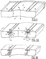
- FIGS. 1 and 1A schematically show an expanded polystyrene plate, 10, the thickness E of which is such, for example of the order of 50 mm, that said plate limited by parallel facing faces 11 and 12 is rigid.
- the facing faces have a slightly wavy outline with, for the facing face 11, a part 13 with radius of curvature R connected to adjacent parts 14 and 15 of the same radius of curvature R by flats 16 and 17.
- Such a plate, the length L of which can be of the order of 1.20 m can be manufactured by molding or, preferably, by cutting using heated wires, vibrating or not, in blocks. of large-scale PES.
- the plate 10 is cut, preferably using heated wires, vibrating or not, to provide recesses 201, 202 (FIG. 1A) in the vicinity of the facing face 11 and the recesses 21ures, 212 which originate in the recesses 20 and which open onto the facing face 12. More precisely, each recess 20 extends substantially parallel to the facing face to which it is adjacent and has a somewhat contours in cross section.
- the invention provides for folding the plate to bring the contact faces 21 and the contacting faces into contact with each other by taking advantage of the deformation capacity of the thin strip e ; when the folding is finished, the convex parts 13, 14 and 15 of the initial plate then form with the flats 16 and 17 a substantially continuous surface of radius R, both on the facing face 11 and on the underside face 12 at contact of the cylindrical surface to be insulated.
- the invention provides for filling with adhesive, for example of the polyurethane type, the facing faces 35 and 36 of the recesses before bringing them into contact with one another.
- maintaining the shape given by folding is obtained by placing one or more adhesive tapes on the face 12.
- the maintenance in the desired shape of a folded plate is obtained by shaping the faces 35 and 36 so that one of them, for example the face 35, is cut along a groove 50 while the facing face 36 is cut to form a rib 51 of conjugate section of the groove 50 and into which it can penetrate, to provide a wedging effect, it being understood that the blocking action which results from the nesting of the rib 51 in the groove 50 can be completed by one and / or both of the aforementioned means, namely the use of adhesive on the faces 35, 36 or a tape on the face of facing 12.
- a rigid expanded polystyrene sheet due to its thickness can, using the method according to the invention, be shaped to form the insulating coating of a tube T, including a relatively large diameter, on the external surface S of which it is reported.
- a plate 10 of width corresponding to the circumference of the tube to be filled is cut according to a multiplicity of recesses 201, ..., 20 n and of corresponding recesses then is folded around the tube T, the ends of the plate being joined together by the interlocking of grooves and ribs of conjugate shapes, as shown in the part referenced 40 of Figure 2A (which aims at a cutout embodiment according to Figure 1A) or in Figure 2B (which aims at an embodiment to cutouts according to Figure 1B).
- the starting plate 60 in EPS is a rectangular flat plate of thickness E (for example 50 mm like the plate 10 of the previous embodiment) whose facing faces are shown at 61 and 62 and whose length L, can be of the order of 1.20 m.
- E thickness
- the invention proposes to cut the plate, preferably here also with using vibrating or non-vibrating heated wires, as shown in FIG.
- the cutting of the plate 60 is also carried out to form hollows 701, 702, 703, coming from the recesses 65, 661 and 662, respectively, and which open onto the facing face 62, each hollowing being of substantially triangular cross section and therefore limited by flat faces like 71 and 72 for the 701 hole .
- the invention proposes, as explained above, to coat the facing faces as 71 and 72 of the recesses, advantageously an adhesive of the polyurethane type or, as a variant, of add on one of the facing faces, which may be the face 61, one or more adhesive tapes 80 which "block" the device in the shape which has been imparted to it and which corresponds to the rounded angle AR of the product O to protect.
- a wedging device of the type shown in FIG. 5 can also be produced using a plate 80, cut as shown in FIG.
- a device such as that described with reference to Figures 3 to 5 or 6 may, of course, have other applications than that of a packing block.
- it can be used to form part of a volume of generally cylindrical shape whose direction of the generators is parallel to the direction of the length L of the plate and whose cross section is, for example , a rectangle with rounded corners, or a wavy curve, or any closed curve.
Abstract
Description
L'invention concerne un procédé de fabrication d'objets en polystyrène expansé et les objets ainsi obtenus.The invention relates to a method of manufacturing expanded polystyrene objects and the objects thus obtained.
On sait que le polystyrène expansé est d'un emploi courant dans les domaines de l'emballage et de l'isolation et que, s'il est parfois mis en oeuvre sans être conformé il l'est le plus souvent, toutefois, après mise en forme par moulage, ce qui conduit à des produits finis d'excellente qualité mais exige, bien entendu, un investissement important en moules et outillages de fabrication. C'est pourquoi on fait appel, aussi bien dans le domaine de l'isolation que dans celui de l'emballage, au découpage et/ou à l'usinage de blocs ou de plaques en polystyrène expansé (PSE), le découpage à l'aide de fils chauffés, vibrants ou non, étant la solution préférée dans la mesure où elle permet d'obtenir une surface après découpage plus lisse que celle obtenue par enlèvement mécanique de matière. Ces techniques de travail des blocs ou plaques de PSE, de même que des techniques spécifiques de fabrication (comme le déroulage) permettent d'obtenir des feuilles de très faible épaisseur, relativement souples et qui peuvent de ce fait être déformées pour épouser des surfaces autres que planes. De telles feuilles minces ne peuvent pas, cependant, fournir les caractéristiques d'isolation ou de résistance aux chocs, -dans le domaine de l'emballage-, qui sont celles de plaques plus épaisses, par exemple de l'ordre de 50 mm, lesquelles sont rigides, indéformables et doivent nécessairement être moulées ou découpées à la configuration souhaitée pour leur utilisation.It is known that expanded polystyrene is in common use in the fields of packaging and insulation and that, if it is sometimes used without being conformed it is most often, however, after installation. in shape by molding, which leads to finished products of excellent quality but requires, of course, a significant investment in molds and manufacturing tools. This is why recourse is had, both in the field of insulation and in that of packaging, to cutting and / or machining of blocks or sheets of expanded polystyrene (EPS), cutting to size. using heated wires, vibrating or not, being the preferred solution insofar as it makes it possible to obtain a smoother surface after cutting than that obtained by mechanical removal of material. These techniques for working with blocks or sheets of EPS, as well as specific manufacturing techniques (such as peeling) make it possible to obtain sheets of very small thickness, relatively flexible and which can therefore be deformed to match other surfaces. that planes. Such thin sheets cannot, however, provide the insulation or impact resistance characteristics, - in the field of packaging -, which are those of thicker plates, for example of the order of 50 mm, which are rigid, non-deformable and must necessarily be molded or cut to the desired configuration for their use.
Il se pose, dans ces conditions, le problème de pouvoir aisément façonner, à partir d'une plaque de PSE rigide en raison de son épaisseur et sans briser ladite plaque, un objet de forme générale cylindrique, -au sens le plus général de ce terme-, dont la section droite peut être une courbe ouverte ou fermée, de forme quelconque, y compris à partie(s) à faible(s) rayon(s) de courbure.Under these conditions, the problem arises of being able to easily shape, from a rigid EPS sheet due to its thickness and without breaking said plate, an object of generally cylindrical shape, in the most general sense of this. term-, the cross section of which can be an open or closed curve, shaped any, including part (s) with small radius (s) of curvature.
C'est, d'une façon générale, un but de l'invention de fournir une solution à ce problème.It is, in general, an object of the invention to provide a solution to this problem.
C'est, à cet égard, un but de l'invention de fournir un procédé de fabrication d'objets en PSE à partir de blocs ou plaques de PSE relativement épais et rigides dont la mise en oeuvre puisse être effectuée à l'aide des outils habituels de travail du PSE.It is, in this regard, an object of the invention to provide a method of manufacturing PES objects from relatively thick and rigid blocks or plates of PSE, the implementation of which can be carried out using usual PES working tools.
C'est, encore, un but de l'invention de fournir un tel procédé dont la faisabilité industrielle est telle qu'il puisse être mis en oeuvre dans de bonnes conditions de rentabilité économique.It is, again, an object of the invention to provide such a process, the industrial feasibility of which is such that it can be implemented under good conditions of economic profitability.
Un procédé selon l'invention, de fabrication d'objets en polystyrène expansé à partir de blocs ou plaques de PSE rigides en raison de leur épaisseur est caractérisé en ce que lesdites plaques, -préalablement obtenues le cas échéant à partir de blocs-, sont découpées dans leur épaisseur pour ménager au voisinage d'une de leurs faces de parement :
- . au moins un évidement de faible épaisseur s'étendant sensiblement parallèlement à ladite face de parement ; et
- . au moins une creusure régnant entre ledit évidement et l'autre face de parement sur laquelle elle débouche.
- . at least one thin recess extending substantially parallel to said facing face; and
- . at least one recess prevailing between said recess and the other facing face on which it opens.
Les plaques découpées pour y ménager le ou les évidement(s) et creusure(s) présentent alors, au voisinage du ou des évidement(s), suffisamment de souplesse pour pouvoir être pliées en une, et de préférence plusieurs zones s'étendant parallèlement à la direction longitudinale des creusures, de sorte que lesdites plaques peuvent être mises en forme suivant des cylindres, -au sens général de ce terme-, dont la direction des génératrices est précisément celle du ou des axes de pliage.The plates cut out to provide the recess (s) and recess (s) therein then have, in the vicinity of the recess (s), sufficient flexibility to be able to be folded in one, and preferably several zones extending in parallel in the longitudinal direction of the hollows, so that said plates can be shaped according to cylinders, - in the general sense of this term -, the direction of the generatrices of which is precisely that of the folding axis or axes.
En disposant à proximité les uns des autres plusieurs évidements et les creusures qui leur sont associées, il est possible d'accroître le nombre de "zones de pliage" et, de ce fait, de conformer la plaque de PSE, par ailleurs rigide, suivant un objet dont le contour présente un ou des rayon(s) de courbure relativement faible(s).By having several recesses and the recesses associated therewith close together, it is possible to increase the number of "folding zones" and, therefore, to conform the EPS sheet, which is otherwise rigid, according to an object whose contour has one or more relatively small radius (s) of curvature.
Compte-tenu de l'élasticité intrinsèque des bandes minces ménagées dans les plaques de PSE au voisinage des évidements, le pliage qui est fait desdites plaques après découpe ne peut être conservé qu'à l'aide de moyens auxiliaires et l'invention prévoit de maintenir la forme définitive des objets que l'on souhaite obtenir soit à l'aide d'organes analogues à des bandes de cerclage, comme des rubans adhésifs, soit en rapportant, -de préférence sur les faces en regard des creusures-, un adhésif rendu opératoire lorsque lesdites faces sont mises en contact, soit encore en prévoyant des formes complémentaires sur les faces en regard des creusures qui, lors du pliage, coopèrent entre elles, quelque peu à la façon d'un emboîtement, d'un embrèvement ou analogue.Given the intrinsic elasticity of the thin strips formed in the EPS sheets in the vicinity of the recesses, the folding which is made of said sheets after cutting can only be preserved using auxiliary means and the invention provides for maintain the final shape of the objects which it is desired to obtain either with the aid of organs similar to strapping bands, such as adhesive tapes, or by adding, preferably on the facing faces of the recesses, an adhesive rendered operational when said faces are brought into contact, or again by providing complementary shapes on the opposite faces of the recesses which, during folding, cooperate with each other, somewhat in the manner of an interlocking, a recess or the like .
Lorsque le procédé est mis en oeuvre à partir de blocs de PSE et non de plaques, de tels blocs sont d'abord découpés suivant des plaques dont les faces de parements peuvent être planes, bombées, ondulées, ... etc et cela par les techniques connues d'usinage et/ou à l'aide de fils chauffés qui provoquent la fusion de la matière lors de leur passage au travers desdits blocs.When the process is implemented from EPS blocks and not from plates, such blocks are first cut according to plates, the faces of which may be flat, curved, wavy, etc., and this by means of the known techniques for machining and / or using heated wires which cause the material to melt when they pass through said blocks.
D'autres caractéristiques et avantages de l'invention apparaîtront de la description qui suit, faite à titre d'exemple et en référence au dessin annexé dans lequel :
- la figure 1 est une vue schématique en perspective d'une plaque de polystyrène expansé avant mise en oeuvre du procédé de l'invention ;
- la figure 1A est une vue de la plaque de la figure 1 après découpe conformément au procédé selon l'invention ;
- la figure 2A est une vue partielle, en coupe, d'un objet fabriqué par le procédé de l'invention ;
- les figures 1B et 2B sont des vues analogues à celles des figures 1A et 2A mais pour une variante de réalisation ;
- la figure 3 est une vue analogue à celle de la figure 1 mais pour une autre réalisation ;
- la figure 4 est une vue analogue à celle de la figure 1A, mais pour la réalisation de la figure 3 ;
- la figure 5 est une vue schématique en perspective d'un objet obtenu à l'aide du procédé de l'invention ;
- la figure 6 est une vue schématique d'une découpe de plaque.
- Figure 1 is a schematic perspective view of an expanded polystyrene plate before implementing the method of the invention;
- Figure 1A is a view of the plate of Figure 1 after cutting according to the method according to the invention;
- FIG. 2A is a partial view, in section, of an object manufactured by the method of the invention;
- Figures 1B and 2B are views similar to those of Figures 1A and 2A but for an alternative embodiment;
- Figure 3 is a view similar to that of Figure 1 but for another embodiment;
- Figure 4 is a view similar to that of Figure 1A, but for the embodiment of Figure 3;
- Figure 5 is a schematic perspective view of an object obtained using the method of the invention;
- Figure 6 is a schematic view of a plate cutout.
On se réfère d'abord aux figures 1 et 1A qui montrent schématiquement une plaque de polystyrène expansé, 10, dont l'épaisseur E est telle, par exemple de l'ordre de 50 mm, que ladite plaque limitée par des faces de parement parallèles 11 et 12 est rigide. Dans la réalisation décrite et représentée, les faces de parement sont à contour légèrement ondulé avec, pour la face de parement 11, une partie 13 à rayon de courbure R reliée à des parties adjacentes 14 et 15 de même rayon de courbure R par des méplats 16 et 17. Une telle plaque, dont la longueur L peut être de l'ordre de 1,20 m peut être fabriquée par moulage ou, de préférence, par découpe à l'aide de fils chauffés, vibrants ou non, dans des blocs de PSE de grande dimension.Reference is first made to FIGS. 1 and 1A which schematically show an expanded polystyrene plate, 10, the thickness E of which is such, for example of the order of 50 mm, that said plate limited by parallel facing
Selon l'invention, la plaque 10 est découpée, de préférence à l'aide de fils chauffés, vibrants ou non, pour y ménager des évidements 20₁, 20₂ (figure 1A) au voisinage de la face de parement 11 et des creusures 21₁, 21₂ qui prennent naissance dans les évidements 20 et qui débouchent sur la face de parement 12. De façon plus précise, chaque évidement 20 s'étend sensiblement parallèlement à la face de parement à laquelle il est adjacent et présente en section droite un contour quelque peu en forme de "boutonnière", c'est-à-dire à bord rectiligne 25 relié à ses extrémités par des arrondis 26 et 27 à deux bords 28 et 29 sensiblement parallèles au bord 25 mais dont la longueur totale est inférieure à celle dudit bord de sorte qu'est ménagée, entre les extrémités 30 et 31 desdits bords 28 et 29, une discontinuité d qui est l'origine de la creusure 21₁ associée à l'évidement 20₁, creusure qui est limitée par des faces en regard 35 et 36 obliques par rapport à la direction des bords 25, 28 et 29.According to the invention, the
La découpe de la plaque 10 suivant les évidements 20 et les creusures 21, -d'où la matière est retirée-, confère à ladite plaque, -plus précisément à la bande d'épaisseur e limitée par la face de parement 11 et le ou les évidements 20-, une certaine souplesse ou capacité de déformation par pliage autour de zones comme z₁, z₂ d'axe(s) parallèle(s) à la direction montrée en X sur la figure 1A et qui est celle de la longueur L de la plaque.The cutting of the
Pour mettre en forme une plaque découpée comme défini ci-dessus, par exemple pour constituer un revêtement isolant d'une surface cylindrique, l'invention prévoit de plier la plaque pour rapprocher et amener au contact les faces en regard des creusures 21 en tirant parti de la capacité de déformation de la bande de faible épaisseur e ; lorsque le pliage est terminé, les parties bombées 13, 14 et 15 de la plaque initiale forment alors avec les méplats 16 et 17 une surface sensiblement continue de rayon R, tant sur la face de parement 11 que sur la face d'intrados 12 au contact de la surface cylindrique à isoler.To shape a cut plate as defined above, for example to form an insulating coating on a cylindrical surface, the invention provides for folding the plate to bring the contact faces 21 and the contacting faces into contact with each other by taking advantage of the deformation capacity of the thin strip e ; when the folding is finished, the
Pour le maintien de la plaque dans la condition pliée, l'invention prévoit de garnir de colle, par exemple du type polyuréthanne, les faces en regard 35 et 36 des creusures avant de les rapprocher au contact l'une de l'autre.To maintain the plate in the folded condition, the invention provides for filling with adhesive, for example of the polyurethane type, the facing
En variante, le maintien de la forme donnée par pliage est obtenu en plaçant sur la face 12 un ou des rubans adhésifs.As a variant, maintaining the shape given by folding is obtained by placing one or more adhesive tapes on the
Dans encore une autre variante, illustrée sur la figure 1B, le maintien dans la forme souhaitée d'une plaque pliée est obtenu en conformant les faces 35 et 36 pour que l'une d'elles, par exemple la face 35, soit découpée suivant une gorge 50 tandis que la face en regard 36 est découpée pour former une nervure 51 de section conjuguée de la gorge 50 et dans laquelle elle peut pénétrer, pour procurer un effet de coincement, étant entendu que l'action de blocage qui résulte de l'emboîtement de la nervure 51 dans la gorge 50 peut être complétée par l'un et/ou les deux des moyens précédemment mentionnés, à savoir l'utilisation d'adhésif sur les faces 35, 36 ou d'un ruban sur la face de parement 12.In yet another variant, illustrated in FIG. 1B, the maintenance in the desired shape of a folded plate is obtained by shaping the
Une plaque de polystyrène expansé rigide en raison de son épaisseur peut, à l'aide du procédé selon l'invention, être mise en forme pour constituer le revêtement isolant d'un tube T, y compris de diamètre relativement important, sur la surface externe S duquel il est rapporté. Pour ce faire, une plaque 10 de largeur correspondant à la circonférence du tube à garnir est découpée suivant une multiplicité d'évidements 20₁, ..., 20n et de creusures correspondantes puis est pliée autour du tube T, les extrémités de la plaque étant solidarisées entre elles par l'emboîtement de gorges et nervures de formes conjuguées, comme montré dans la partie référencée 40 de la figure 2A (qui vise une réalisation à découpes selon la figure 1A) ou sur la figure 2B (qui vise une réalisation à découpes selon la figure 1B).A rigid expanded polystyrene sheet due to its thickness can, using the method according to the invention, be shaped to form the insulating coating of a tube T, including a relatively large diameter, on the external surface S of which it is reported. To do this, a
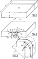
On se réfère maintenant aux figures 3 à 5 relatives à une autre forme de réalisation. Dans celle-ci, la plaque de départ 60 en PSE est une plaque plane rectangulaire d'épaisseur E (par exemple 50 mm comme la plaque 10 de la réalisation précédente) dont les faces de parement sont montrées en 61 et 62 et dont la longueur L, peut être de l'ordre de 1,20 m. Pour, à partir d'une telle plaque, réaliser un dispositif de calage destiné à être rapporté sur l'angle arrondi AR d'un produit O, figure 5, l'invention propose de découper la plaque, -de préférence ici aussi à l'aide de fils chauffés vibrants ou non-, comme montré sur la figure 4, c'est-à-dire suivant un évidement 65 de même forme que les évidements 20 de la réalisation précédente et deux évidements 66₁ et 66₂ d'envergure moitié de l'évidement 65, les plans moyens montrés en 67₁ et 67₂ des évidements 66 étant coplanaires au plan moyen 68 de l'évidement 65. Comme dans la réalisation des figures 1A et 1B, la découpe de la plaque 60 est également conduite pour former des creusures 70₁, 70₂, 70₃, issues des évidements 65, 66₁ et 662, respectivement, et qui débouchent sur la face de parement 62, chaque creusure étant à section droite sensiblement triangulaire et limitée, de ce fait, par des faces planes comme 71 et 72 pour la creusure 70₁.Reference is now made to FIGS. 3 to 5 relating to another embodiment. In this, the
L'utilisation d'une telle plaque découpée 60 est identique à celle des plaques 10 des réalisations précédentes. Par pliage de la plaque dans ses zones comme z₁, z₂, z₃, z₄ de la bande de faible épaisseur 75 régnant entre la face de parement 61 et les évidements 65 et 66, on amène au contact les unes des autres les faces planes en regard des creusures 70 jusqu'à donner à la plaque la forme montrée sur la figure 5. Pour le maintien de la plaque dans cette condition, l'invention propose, comme explicité ci-dessus, de revêtir d'adhésif les faces en regard comme 71 et 72 des creusures, avantageusement un adhésif du type polyuréthanne ou, en variante, de rapporter sur l'une des faces de parement, qui peut être la face 61, un ou des rubans adhésifs 80 qui "bloquent" le dispositif dans la forme qui lui a été impartie et qui correspond à l'angle arrondi AR du produit O à protéger. Un dispositif de calage du type de celui montré sur la figure 5 peut également être réalisé à l'aide d'une plaque 80, découpée comme montré sur la figure 6, c'est-à-dire pour ménager un évidement 81 s'étendant sensiblement parallèlement à la face de parement 82 et une creusure 83 règnant entre ledit évidement et l'autre face de parement 84, ladite creusure étant limitée par des faces 85 et 86, inclinées d'un angle voisin de 45° sur un plan médian de la creusure et qui sont reliées à la face 85 de l'évidement 81 qui est parallèle aux parements 82 et 84 par des surfaces arrondies 88 et 89, respectivement.The use of such a
Un dispositif tel que celui décrit en référence aux figures 3 à 5 ou 6 peut, bien entendu, avoir d'autres applications que celui d'une cale d'emballage. C'est, ainsi, qu'il peut être utilisé pour constituer une partie d'un volume de forme générale cylindrique dont la direction des génératrices est parallèle à la direction de la longueur L de la plaque et dont la section droite est, par exemple, un rectangle à coins arrondis, ou une courbe ondulée, ou une courbe fermée quelconque.A device such as that described with reference to Figures 3 to 5 or 6 may, of course, have other applications than that of a packing block. Thus, it can be used to form part of a volume of generally cylindrical shape whose direction of the generators is parallel to the direction of the length L of the plate and whose cross section is, for example , a rectangle with rounded corners, or a wavy curve, or any closed curve.
Claims (8)
Applications Claiming Priority (2)
| Application Number | Priority Date | Filing Date | Title |
|---|---|---|---|
| FR9311034A FR2710003B1 (en) | 1993-09-16 | 1993-09-16 | Process for the production of expanded polystyrene objects and objects thus obtained. |
| FR9311034 | 1993-09-16 |
Publications (1)
| Publication Number | Publication Date |
|---|---|
| EP0644036A1 true EP0644036A1 (en) | 1995-03-22 |
Family
ID=9450928
Family Applications (1)
| Application Number | Title | Priority Date | Filing Date |
|---|---|---|---|
| EP94402026A Withdrawn EP0644036A1 (en) | 1993-09-16 | 1994-09-12 | Process for making objects from foamed polystyrene and objects thus obtained |
Country Status (3)
| Country | Link |
|---|---|
| EP (1) | EP0644036A1 (en) |
| CZ (1) | CZ223494A3 (en) |
| FR (1) | FR2710003B1 (en) |
Cited By (5)
| Publication number | Priority date | Publication date | Assignee | Title |
|---|---|---|---|---|
| WO1996032605A1 (en) * | 1995-04-13 | 1996-10-17 | Imperial Chemical Industries Plc | Non-planar evacuated insulation panels and a method for making same |
| EP0763690A2 (en) * | 1995-09-14 | 1997-03-19 | Schuller International, Inc. | Method of kerfing insulation boards and ducts and duct liners formed from said boards |
| GB2309768A (en) * | 1996-02-01 | 1997-08-06 | Superglass Insulation Ltd | An insulation material which may be divided along lines of weakness |
| EP0924036A2 (en) * | 1997-12-17 | 1999-06-23 | Peter Kessler | Punching apparatus for producing mitred cuts in a resilient material |
| ITUD20090060A1 (en) * | 2009-03-26 | 2010-09-27 | Mario Rigo | PROCEDURE FOR THE CONSTRUCTION OF A CURVED PANEL, TOOL FOR THE REALIZATION OF SUCH PANEL AND PANEL SO MADE ' |
Citations (13)
| Publication number | Priority date | Publication date | Assignee | Title |
|---|---|---|---|---|
| DE120977C (en) * | ||||
| DE643525C (en) * | 1934-09-04 | 1937-04-10 | Wilhelm Kaiser | Jointless corner connections on the outside, especially for furniture |
| GB1137121A (en) * | 1964-10-21 | 1968-12-18 | Lo Dense Fixings Rugby Ltd | Improvements in and in the manufacture of insulated ducting, tubing or casing |
| FR2184651A1 (en) * | 1972-05-12 | 1973-12-28 | Muellender Gernot | |
| DE2541373A1 (en) * | 1975-09-17 | 1977-03-31 | Joachim Dipl Chem Dr Steffens | Continuous pipe lagging prodn. - by foaming between films in two adjacent semicircular sections and folding sections together |
| FR2323529A1 (en) * | 1974-01-11 | 1977-04-08 | Valeri Ebenisterie Ind | Folding strip material for casing radio and TV sets - has opposite face of consecutive sections butting together to form rounded corner |
| EP0019026A1 (en) * | 1979-05-11 | 1980-11-26 | Societe Industrielle De Liaisons Electriques - Silec | Carrier element for the realisation of unitary fibre optics cable elements and manufacturing process |
| EP0117388A1 (en) * | 1983-01-27 | 1984-09-05 | Greiner K.G. | Reservoir insulation |
| FR2582078A1 (en) * | 1985-05-14 | 1986-11-21 | Soliso | Self-locking thermal insulation sleeve for a rigid or semi-flexible pipeline |
| EP0302845A2 (en) * | 1987-08-06 | 1989-02-08 | Robbins, Edward S., III | Foldable plastic products and process and apparatus for making same |
| DE3821611A1 (en) * | 1988-06-27 | 1989-12-28 | Reckord Geb Kirchhoff Rita | Method for producing furniture parts with at least one rounded edge, and furniture part |
| DE3901237A1 (en) * | 1989-01-17 | 1990-07-19 | Traber Excellent Gfk Reisemobi | Process for producing wall parts for travel vehicles |
| DE4103426A1 (en) * | 1990-02-05 | 1991-08-08 | Texas Ind Insulations | FLAT, RECTANGULAR COMPOSITE INSULATION |
Family Cites Families (1)
| Publication number | Priority date | Publication date | Assignee | Title |
|---|---|---|---|---|
| US2203027A (en) * | 1938-04-07 | 1940-06-04 | Onsrud Machine Works Inc | Bending table |
-
1993
- 1993-09-16 FR FR9311034A patent/FR2710003B1/en not_active Expired - Fee Related
-
1994
- 1994-09-12 EP EP94402026A patent/EP0644036A1/en not_active Withdrawn
- 1994-09-13 CZ CZ942234A patent/CZ223494A3/en unknown
Patent Citations (13)
| Publication number | Priority date | Publication date | Assignee | Title |
|---|---|---|---|---|
| DE120977C (en) * | ||||
| DE643525C (en) * | 1934-09-04 | 1937-04-10 | Wilhelm Kaiser | Jointless corner connections on the outside, especially for furniture |
| GB1137121A (en) * | 1964-10-21 | 1968-12-18 | Lo Dense Fixings Rugby Ltd | Improvements in and in the manufacture of insulated ducting, tubing or casing |
| FR2184651A1 (en) * | 1972-05-12 | 1973-12-28 | Muellender Gernot | |
| FR2323529A1 (en) * | 1974-01-11 | 1977-04-08 | Valeri Ebenisterie Ind | Folding strip material for casing radio and TV sets - has opposite face of consecutive sections butting together to form rounded corner |
| DE2541373A1 (en) * | 1975-09-17 | 1977-03-31 | Joachim Dipl Chem Dr Steffens | Continuous pipe lagging prodn. - by foaming between films in two adjacent semicircular sections and folding sections together |
| EP0019026A1 (en) * | 1979-05-11 | 1980-11-26 | Societe Industrielle De Liaisons Electriques - Silec | Carrier element for the realisation of unitary fibre optics cable elements and manufacturing process |
| EP0117388A1 (en) * | 1983-01-27 | 1984-09-05 | Greiner K.G. | Reservoir insulation |
| FR2582078A1 (en) * | 1985-05-14 | 1986-11-21 | Soliso | Self-locking thermal insulation sleeve for a rigid or semi-flexible pipeline |
| EP0302845A2 (en) * | 1987-08-06 | 1989-02-08 | Robbins, Edward S., III | Foldable plastic products and process and apparatus for making same |
| DE3821611A1 (en) * | 1988-06-27 | 1989-12-28 | Reckord Geb Kirchhoff Rita | Method for producing furniture parts with at least one rounded edge, and furniture part |
| DE3901237A1 (en) * | 1989-01-17 | 1990-07-19 | Traber Excellent Gfk Reisemobi | Process for producing wall parts for travel vehicles |
| DE4103426A1 (en) * | 1990-02-05 | 1991-08-08 | Texas Ind Insulations | FLAT, RECTANGULAR COMPOSITE INSULATION |
Cited By (12)
| Publication number | Priority date | Publication date | Assignee | Title |
|---|---|---|---|---|
| WO1996032605A1 (en) * | 1995-04-13 | 1996-10-17 | Imperial Chemical Industries Plc | Non-planar evacuated insulation panels and a method for making same |
| AU695090B2 (en) * | 1995-04-13 | 1998-08-06 | Huntsman Ici Chemicals Llc | Non-planar evacuated insulation panels and a method for making same |
| US5843353A (en) * | 1995-04-13 | 1998-12-01 | Imperial Chemical Industries Plc | Non-planar evacuated insulation panels and a method for making same |
| EP0763690A2 (en) * | 1995-09-14 | 1997-03-19 | Schuller International, Inc. | Method of kerfing insulation boards and ducts and duct liners formed from said boards |
| EP0763690A3 (en) * | 1995-09-14 | 1998-04-01 | Johns Manville International, Inc. | Method of kerfing insulation boards and ducts and duct liners formed from said boards |
| US5953818A (en) * | 1995-09-14 | 1999-09-21 | Johns Manville International, Inc. | Method of kerfing insulation boards and duct liners and the like formed from said boards |
| US6457237B1 (en) * | 1995-09-14 | 2002-10-01 | Johns Manville International, Inc. | Method of kerfing insulation boards to form duct liners |
| GB2309768A (en) * | 1996-02-01 | 1997-08-06 | Superglass Insulation Ltd | An insulation material which may be divided along lines of weakness |
| GB2309768B (en) * | 1996-02-01 | 1999-10-13 | Superglass Insulation Ltd | Insulation material |
| EP0924036A2 (en) * | 1997-12-17 | 1999-06-23 | Peter Kessler | Punching apparatus for producing mitred cuts in a resilient material |
| EP0924036A3 (en) * | 1997-12-17 | 2000-05-03 | Peter Kessler | Punching apparatus for producing mitred cuts in a resilient material |
| ITUD20090060A1 (en) * | 2009-03-26 | 2010-09-27 | Mario Rigo | PROCEDURE FOR THE CONSTRUCTION OF A CURVED PANEL, TOOL FOR THE REALIZATION OF SUCH PANEL AND PANEL SO MADE ' |
Also Published As
| Publication number | Publication date |
|---|---|
| CZ223494A3 (en) | 1995-04-12 |
| FR2710003B1 (en) | 1995-11-24 |
| FR2710003A1 (en) | 1995-03-24 |
Similar Documents
| Publication | Publication Date | Title |
|---|---|---|
| CA1093356A (en) | Preparation process of an ophthalmic lens | |
| EP0015202B1 (en) | Annular gasket for use in the casting of ophthalmic or optical lenses of organic material, and method of using such a gasket | |
| EP0829658B1 (en) | Driving belt and method of fabrication thereof | |
| FR2715635A1 (en) | Scaling cap for container with threaded neck | |
| CA2166451C (en) | Process and device for making at least part of a tire mould having at least a member moulding a non strippable pattern | |
| CA2351661C (en) | Method for making mechanical parts by decomposition into layers | |
| EP0644036A1 (en) | Process for making objects from foamed polystyrene and objects thus obtained | |
| EP0033266B1 (en) | Sealing method, particularly for plastic packaging, and hermetic package obtained by this method | |
| EP1407183B1 (en) | Compressed heat insulation housing | |
| EP0546885B1 (en) | Cylinder for a metal strip continuous casting machine, continous casting machine containing such a cylinder and process for making such a cylinder | |
| EP1523387A1 (en) | Metal plate, method for making same and method for folding same | |
| EP1452793B1 (en) | Equipment support with supporting ribs and its molding method | |
| FR2718075A1 (en) | Method for forming a mold suitable for obtaining an optical lens, corresponding mold and optical lens obtained. | |
| FR2482375A1 (en) | METHOD AND MEANS FOR MANUFACTURING FRONT COLLECTORS OF ELECTRIC MOTORS | |
| CA2882402C (en) | Device and method for producing preforms | |
| FR2731490A1 (en) | Process of fabrication brush joint for use with rotating shafts | |
| FR2831645A1 (en) | Thermal insulation element especially for pipes, comprises tube of compressed mineral wool felt with outer retaining film layer | |
| FR3066136A1 (en) | HALF MOLD HAVING A CYLINDRICAL ASSEMBLY SIDE AND METHOD OF MAKING SAME | |
| FR2719255A1 (en) | Device for separating the elements of a blank of cut cardboard. | |
| FR2530985A1 (en) | Mould for obtaining a grid, particularly by injection, method and means of manufacture and use. | |
| EP0627303A1 (en) | Rotary forming apparatus for carton blank and method of manufacturing same | |
| FR2465580A1 (en) | Mould for masking spectacle side arm flanges during polishing - avoids need for individual moulds to prefabricate masks | |
| CH716752A2 (en) | Cheese mold, in particular for cheese of the county type, and method of manufacturing such a mold. | |
| WO2003011582A2 (en) | Method for making a donut-shaped toy or a sport article | |
| FR2763269A1 (en) | Procedure for bevelling of ophthalmic lens |
Legal Events
| Date | Code | Title | Description |
|---|---|---|---|
| PUAI | Public reference made under article 153(3) epc to a published international application that has entered the european phase |
Free format text: ORIGINAL CODE: 0009012 |
|
| AK | Designated contracting states |
Kind code of ref document: A1 Designated state(s): BE DE DK ES GB IT LU NL |
|
| 17P | Request for examination filed |
Effective date: 19950915 |
|
| 17Q | First examination report despatched |
Effective date: 19961120 |
|
| STAA | Information on the status of an ep patent application or granted ep patent |
Free format text: STATUS: THE APPLICATION IS DEEMED TO BE WITHDRAWN |
|
| 18D | Application deemed to be withdrawn |
Effective date: 19970402 |