EP0643310A1 - Device for monitoring the discharge of a plurality of series connected batteries - Google Patents
Device for monitoring the discharge of a plurality of series connected batteries Download PDFInfo
- Publication number
- EP0643310A1 EP0643310A1 EP94402020A EP94402020A EP0643310A1 EP 0643310 A1 EP0643310 A1 EP 0643310A1 EP 94402020 A EP94402020 A EP 94402020A EP 94402020 A EP94402020 A EP 94402020A EP 0643310 A1 EP0643310 A1 EP 0643310A1
- Authority
- EP
- European Patent Office
- Prior art keywords
- batteries
- discharge
- hand
- terminals
- battery
- Prior art date
- Legal status (The legal status is an assumption and is not a legal conclusion. Google has not performed a legal analysis and makes no representation as to the accuracy of the status listed.)
- Granted
Links
Images


Classifications
-
- G—PHYSICS
- G01—MEASURING; TESTING
- G01R—MEASURING ELECTRIC VARIABLES; MEASURING MAGNETIC VARIABLES
- G01R31/00—Arrangements for testing electric properties; Arrangements for locating electric faults; Arrangements for electrical testing characterised by what is being tested not provided for elsewhere
- G01R31/36—Arrangements for testing, measuring or monitoring the electrical condition of accumulators or electric batteries, e.g. capacity or state of charge [SoC]
- G01R31/396—Acquisition or processing of data for testing or for monitoring individual cells or groups of cells within a battery
Definitions
- the present invention relates to a device for controlling the discharge of a plurality of batteries connected in series.
- the invention relates more particularly to a device which makes it possible to prevent a deep discharge of a battery of a set of batteries connected in series by activating signaling means when a predetermined state of discharge is reached by at least one of the batteries .
- the publication FR-A-2.112.467 describes a device for signaling the insufficient voltage present at the terminals of a battery, which delivers a signal as soon as the voltage of the battery drops below a preset threshold.
- one of the batteries may already be deeply discharged even though the value of the voltage across the terminals of the assembly indicates a satisfactory overall state of charge.
- the object of the present invention is therefore to overcome the drawbacks of the prior art by proposing a device making it possible to control the individual discharge of a plurality of batteries connected in series.
- the performance of a set of batteries connected in series is indeed limited by the least charged battery of this set. Exceeding a discharge threshold preselected by one of the batteries will therefore inform the driver of the actual state of all the batteries.
- the discharge threshold is adjusted by a control signal generated by the central unit and transmitted simultaneously with all the modules by the first connecting conductor.
- the processing means consists of a photocoupler associated with an RC circuit.
- the switch consists of a MOSFET transistor associated with a diode.
- the electric motor 3 is supplied by a plurality of batteries 2 connected in series via a variator 3 '.
- the use of a plurality of batteries in series for the propulsion of an electric vehicle is made necessary because of the low value, of the order of ten volts, of the voltage across a single battery .
- the electric motors equipping a motor vehicle require a supply voltage of the order of a hundred volts.
- the Joule effect losses in the conductors decrease with the increase in the voltage of the power source.
- the batteries preferably have identical characteristics.
- each battery 2 At the terminals of each battery 2 are connected respectively the inputs E+ and E ⁇ of one and of a single module 1.
- a first connecting conductor 4 connects the central unit 6 and the modules 1 to each other in series.
- a second connecting conductor 5 connects the warning means 7 and the modules 1 in parallel.
- Each module 1 self-powers on the battery 2 which it controls, but however consumes only a negligible current compared to the self-discharge of said battery.
- the alert means 7 are connected on the one hand to the positive terminal B+ of all the batteries 2 connected in series and on the other hand to the output S of each module 1 via the second connection conductor 5.
- Selection means 8 are connected to the central unit 6.
- the selection means which can be constituted by a numeric keyboard arranged on the dashboard and connected to the central unit. These selection means 8 allow the driver or a computer, preprogrammed, to choose the battery discharge threshold from which the alert means 7 will be activated in order to take appropriate measures. These measures can be varied depending on the battery discharge threshold selected, so a battery discharge threshold of 100% requires immediate recharging of the batteries if one does not want to damage it while a discharge threshold selected by 80% will only require a reduction in vehicle speed to save the remaining battery charge.
- the central unit 6 comprises combining means 6a which transform the value of the discharge threshold displayed using the selection means into a voltage threshold.
- the electromotive force of a battery is in fact to a certain extent representative of the residual electric charge contained in it.
- the combining means receive as input signals I, T and s representative at each instant respectively of the current delivered by all the batteries, of the ambient temperature and of the value of the chosen discharge threshold. These signals are delivered by sensors known elsewhere and not shown.
- the voltage threshold corresponding to the discharge threshold chosen using the selection means 7 is determined by the combination means 6a.
- the residual charge Q res contained in a battery at a given instant and therefore the discharge threshold of the latter relative to a nominal state of charge can in fact be estimated according to a known method which consists in integrating with respect to time the current I delivered by the latter, between an instant when the charge of the latter is known and the instant t at which it is desired to know the residual charge Q res .
- this method is only applicable under conditions, temperature in particular, constant during the measurement.
- Conversion means 6b installed in the central unit receive the input signal from the combination means and transform it into a control signal generated in the form of a periodic signal modulated in pulse width: the signal of command includes an amplitude level A 'and duration a * T followed by a zero amplitude level of duration (a-1) * T.
- the parameter a between 0 and 1, is determined according to the discharge threshold selected using the selection means.
- each module 1 comprises comparator means 1c connected on the one hand to a reference voltage source 1b and on the other hand to a processing means 1a.
- the reference voltage source is constituted by a Zener diode Z1 connected in series with a resistor R1.
- a switch 1d controlled by the output of the comparator means 1c is connected to the output S of the module 1.
- the switch 1d is constituted by a diode D2 connected in series with a MOSFET transistor T2.
- each module 1 comprises a supply line L + connected to the input E+ of the module and a supply line L- connected to the input E ⁇ .
- a resistor R1 is connected in series with a Zener diode Z1.
- a capacitor C1 is mounted between the line L- and the common point between the resistor R1 and the diode Z1.
- a resistor R2 is mounted between the common point between the diode Z1 and the resistor R1 and the non-inverting input of a comparator A.
- a resistor R3 is mounted between the non-inverting input and the output of comparator A.
- the positive supply terminal of comparator A is connected to line L-.
- the negative comparator supply terminal is connected to line L-.
- the processing means 1a comprises an optocoupler associated with an RC circuit.
- the optocoupler is made up in a known manner of a light-emitting diode D1 arranged opposite with an optotransistor T1.
- the optocouplers of each module 1 are connected in series via the first connection conductor 4.
- a low-pass filter of RC type composed of the elements R5, R4, D3 and C2, the arrangement of which has been previously described , is mounted between the emitter of the optotransistor T1 and the inverting input of comparator A.
- the cathode of the diode is connected to the emitter of the optotransistor.
- the optotransistor collector is connected to the L + line.
- the switch 1d is slaved to the output of the comparator A and consists of a diode D2 connected by its cathode to the drain of the transistor T2 and by its anode to the output S of the module.
- the source of transistor T2 is connected to the supply line L-.
- the output of comparator A is connected to the gate of a MOSFET transistor T2.
- the value of the voltage present on the transmission wire 5 is equal to the value of the voltage measured between the terminals of the whole of the plurality of batteries. While the vehicle is running, the batteries gradually discharge, which induces a voltage drop across the terminals.
- the voltage V c across the capacitor C2 is equal to the average value of the voltage V RC applied to the input of the RC circuit. This value is equal to a * V batt taking into account the form of the control signal I uc , generated by the central unit.
- the established regime is achieved after a few successive charge and discharge cycles of the capacitor through the charge resistance R5 and the discharge resistance R4 respectively.
- the load resistor is short-circuited during the discharge phase of the capacitor through the resistor R4.
- the comparator means A compares the reference voltage Vref applied to its non-inverting input and the voltage a * V batt , which therefore amounts to comparing the voltage V batt with the ratio V ref / a.
- Vref reference voltage
- V batt voltage a * V batt
- the transmission wire 5 is at high impedance and the diode 7 '' a of the optocoupler of the alert means 7 is blocked, the indicator light 7b is therefore extinct.
- the switching of the output of the comparator means causes the MOSFET transistor T2 to go from the off state to the on state.
- the potential present on the input E ⁇ of the module is transferred to the transmission wire 5.
- a current therefore flows on the transmission wire, the diode 7 '' a turns on which causes the indicator light 7b to come on.
- the proposed device therefore makes it possible to simply detect a discharge threshold of at least one battery from a set of batteries mounted in series. This discharge threshold is selected by the driver.
- the device can be used to control batteries of all types.
- each module is self-powered by the battery which it controls without, however, penalizing its charge since it consumes only a negligible current compared to the self-discharge of the latter.
Abstract
Description
La présente invention concerne un dispositif de contrôle de la décharge d'une pluralité de batteries montées en série.The present invention relates to a device for controlling the discharge of a plurality of batteries connected in series.
L'invention concerne plus particulièrement un dispositif qui permet de prévenir une décharge profonde d'une batterie d'un ensemble de batteries montées en série en activant des moyens de signalisation lorsque un état prédéterminé de décharge est atteint par l'une au moins des batteries.The invention relates more particularly to a device which makes it possible to prevent a deep discharge of a battery of a set of batteries connected in series by activating signaling means when a predetermined state of discharge is reached by at least one of the batteries .
La publication FR-A-2.112.467 décrit un dispositif de signalisation de l'insuffisance de la tension présente aux bornes d'une batterie, lequel délivre un signal dès que la tension de la batterie descend en dessous d'un seuil préétabli.The publication FR-A-2.112.467 describes a device for signaling the insufficient voltage present at the terminals of a battery, which delivers a signal as soon as the voltage of the battery drops below a preset threshold.
Un tel dispositif monté aux bornes d'un ensemble de batteries en série présente cependant l'inconvénient de ne fournir qu'une indication globale sur l'état de décharge global de cet ensemble, sans indiquer le niveau de décharge individuel de chaque batterie.However, such a device mounted at the terminals of a set of batteries in series has the drawback of only providing an overall indication of the overall discharge state of this set, without indicating the individual discharge level of each battery.
En particulier, l'une des batteries peut déjà être profondément déchargée alors même que la valeur de la tension aux bornes de l'ensemble indique un état global de charge satisfaisant.In particular, one of the batteries may already be deeply discharged even though the value of the voltage across the terminals of the assembly indicates a satisfactory overall state of charge.
L'objet de la présente invention est donc de pallier aux inconvénients de l'art antérieur en proposant un dispositif permettant de contrôler la décharge individuelle d'une pluralité de batteries montées en série. Les performances d'un ensemble de batteries montées en série sont en effet limitées par la batterie la moins chargée de cet ensemble. Le dépassement d'un seuil de décharge présélectionné par l'une des batteries informera donc le conducteur de l'état réel de l'ensemble des batteries.The object of the present invention is therefore to overcome the drawbacks of the prior art by proposing a device making it possible to control the individual discharge of a plurality of batteries connected in series. The performance of a set of batteries connected in series is indeed limited by the least charged battery of this set. Exceeding a discharge threshold preselected by one of the batteries will therefore inform the driver of the actual state of all the batteries.
Selon l'invention, le dispositif est caractérisé en ce qu'il comprend une pluralité de modules individuels identiques respectivement montés en parallèle aux bornes de chacune des batteries et en ce que chaque module possède :
- Une source de tension de référence,
- Un moyen de traitement relié d'une part respectivement aux bornes de la batterie et d'autre part à un premier conducteur de liaison d'une unité centrale à l'ensemble des modules montés en série,
- Un moyen comparateur relié d'une part au générateur et d'autre part au moyen de traitement,
- Un interrupteur asservi à la sortie du moyen comparateur,
et en ce que ledit module commande des moyens d'alerte d'un seuil de décharge de la batterie aux bornes de laquelle il est monté.According to the invention, the device is characterized in that it comprises a plurality of identical individual modules respectively mounted in parallel at the terminals of each of the batteries and in that each module has:
- A reference voltage source,
- A processing means connected on the one hand respectively to the terminals of the battery and on the other hand to a first connecting conductor of a central unit to all of the modules connected in series,
- A comparator means connected on the one hand to the generator and on the other hand to the processing means,
- A slaved switch at the output of the comparator means,
and in that said module controls means for alerting a battery discharge threshold at the terminals of which it is mounted.
Selon une caractéristique de la présente invention, le seuil de décharge est réglé par un signal de commande généré par l'unité centrale et transmis simultanément à l'ensemble des modules par le premier conducteur de liaison.According to a characteristic of the present invention, the discharge threshold is adjusted by a control signal generated by the central unit and transmitted simultaneously with all the modules by the first connecting conductor.
Selon une autre caractéristique de la présente invention, le moyen de traitement est constitué par un photocoupleur associé à un circuit RC.According to another characteristic of the present invention, the processing means consists of a photocoupler associated with an RC circuit.
Avantageusement, l'interrupteur est constitué par un transistor MOSFET associé à une diode.Advantageously, the switch consists of a MOSFET transistor associated with a diode.
On comprendra mieux les buts, aspects et caractéristiques de la présente invention, d'après la description donnée ci-après d'un mode de réalisation de l'invention, présenté à titre d'exemple non limitatif, en se référant aux dessins annexés, dans lesquels :
- la figure 1 est une représentation schématique d'une installation mettant en oeuvre le dispositif suivant la présente invention,
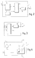
- la figure 2 est une représentation schématique du synoptique fonctionnel correspondant à un module du dispositif conforme à l'invention,
- la figure 3 est un schéma fonctionnel de l'unité centrale du dispositif suivant l'invention,
- la figure 4 est un exemple de réalisation des moyens d'alerte représenté à la figure 1,
- la figure 5 est un exemple de réalisation du circuit électronique constitutif d'un module,
- les figures 6a et 6b représentent l'évolution du signal Vc délivré en sortie du moyen de traitement en fonction du temps pour différentes valeurs de composants électroniques dudit moyen de traitement.
- FIG. 1 is a diagrammatic representation of an installation implementing the device according to the present invention,
- FIG. 2 is a schematic representation of the functional block diagram corresponding to a module of the device according to the invention,
- FIG. 3 is a functional diagram of the central unit of the device according to the invention,
- FIG. 4 is an exemplary embodiment of the alert means shown in FIG. 1,
- FIG. 5 is an exemplary embodiment of the electronic circuit constituting a module,
- Figures 6a and 6b show the evolution of the signal V c output from the processing means as a function of time for different values of electronic components of said processing means.
Conformément aux figures 1 à 5, seules les parties constitutives nécessaires à la compréhension de l'invention ont été représentées.In accordance with FIGS. 1 to 5, only the constituent parts necessary for understanding the invention have been shown.
En référence à la figure 1, l'alimentation du moteur électrique 3 est assurée par une pluralité de batteries 2 montées en série par l'intermédiaire d'un variateur 3'. L'utilisation d'une pluralité de batteries en série pour la propulsion d'un véhicule électrique est rendue nécessaire du fait de la faible valeur, de l'ordre d'une dizaine de Volt, de la tension aux bornes d'une batterie seule. Or, les moteurs électriques équipant un véhicule automobile nécessitent une tension d'alimentation de l'ordre de la centaine de Volt. De plus, pour une même puissance absorbée par le moteur, les pertes par effet Joule dans les conducteurs décroissent avec l'augmentation de la tension de la source d'alimentation. Les batteries présentent de préférence des caractéristiques identiques.With reference to FIG. 1, the
Aux bornes de chaque batterie 2 sont connectées respectivement les entrées E⁺ et E⁻ d'un et d'un seul module 1.At the terminals of each battery 2 are connected respectively the inputs E⁺ and E⁻ of one and of a
Un premier conducteur de liaison 4 relie en série l'unité centrale 6 et les modules 1 entre eux.A first connecting
Un second conducteur de liaison 5 relie en parallèle les moyens d'alerte 7 et les modules 1 entre eux.A second connecting
Chaque module 1 s'autoalimente sur la batterie 2 qu'il contrôle, mais ne consomme cependant qu'un courant négligeable comparativement à l'autodécharge de ladite batterie.Each
Les moyens d'alerte 7 sont reliés d'une part à la borne positive B⁺ de l'ensemble des batteries 2 montées en série et d'autre part à la sortie S de chaque module 1 par l'intermédiaire du second conducteur de liaison 5.The alert means 7 are connected on the one hand to the positive terminal B⁺ of all the batteries 2 connected in series and on the other hand to the output S of each
Des moyens de sélection 8 sont reliés à l'unité centrale 6. Les moyens de sélection, qui peuvent être constitués par un clavier numérique disposé sur le tableau de bord et relié à l'unité centrale. Ces moyens de sélection 8 permettent au conducteur ou à un calculateur, préalablement préprogrammé, de choisir le seuil de décharge des batteries à partir duquel les moyens d'alerte 7 seront activés afin de prendre des mesures appropriées. Ces mesures peuvent être diverses suivant le seuil de décharge de la batterie sélectionné, ainsi un seuil de décharge de la batterie de 100% nécessite une recharge immédiate des batteries si l'on ne veut pas détériorer celle-ci alors qu'un seuil de décharge sélectionné de 80% nécessitera seulement une réduction de la vitesse du véhicule pour ménager la charge résiduelle de la batterie.Selection means 8 are connected to the central unit 6. The selection means, which can be constituted by a numeric keyboard arranged on the dashboard and connected to the central unit. These selection means 8 allow the driver or a computer, preprogrammed, to choose the battery discharge threshold from which the alert means 7 will be activated in order to take appropriate measures. These measures can be varied depending on the battery discharge threshold selected, so a battery discharge threshold of 100% requires immediate recharging of the batteries if one does not want to damage it while a discharge threshold selected by 80% will only require a reduction in vehicle speed to save the remaining battery charge.
En référence à la figure 3, l'unité centrale 6 comprend des moyens de combinaison 6a qui transforment la valeur du seuil de décharge affiché à l'aide des moyens de sélection en un seuil de tension. La force électromotrice d'une batterie est en effet dans une certaine mesure représentative de la charge électrique résiduelle contenue dans celle-ci. Les moyens de combinaison reçoivent en entrée des signaux I, T et s représentatifs à chaque instant respectivement du courant débité par l'ensemble des batteries, de la température ambiante et de la valeur du seuil de décharge choisi. Ces signaux sont délivrés par des capteurs connus par ailleurs et non représentés.With reference to FIG. 3, the central unit 6 comprises combining means 6a which transform the value of the discharge threshold displayed using the selection means into a voltage threshold. The electromotive force of a battery is in fact to a certain extent representative of the residual electric charge contained in it. The combining means receive as input signals I, T and s representative at each instant respectively of the current delivered by all the batteries, of the ambient temperature and of the value of the chosen discharge threshold. These signals are delivered by sensors known elsewhere and not shown.
Le seuil de tension correspondant au seuil de décharge choisi à l'aide des moyens de sélection 7 est déterminé par les moyens de combinaison 6a.The voltage threshold corresponding to the discharge threshold chosen using the selection means 7 is determined by the combination means 6a.
La charge résiduelle Qres contenue dans une batterie à un instant donné et donc le seuil de décharge de celle-ci par rapport à un état de charge nominal, peut en effet être estimée selon une méthode connue qui consiste à intégrer par rapport au temps le courant I délivré par cette dernière, entre un instant où la charge de cette dernière est connue et l'instant t auquel on désire connaître la charge résiduelle Qres. Néanmoins cette méthode ne s'applique que dans des conditions, de température notamment, constantes au cours de la mesure. La charge d'une batterie fluctue en effet avec la température ambiante du milieu dans lequel elle baigne. Des tables effectuant la correspondance entre la charge Q contenue dans une batterie étalon présentant à ses bornes la tension V à différentes températures T ont préalablement été mémorisées dans les moyens de conversion de l'unité centrale ie une fonction de la forme Qres=f(T,V).The residual charge Q res contained in a battery at a given instant and therefore the discharge threshold of the latter relative to a nominal state of charge, can in fact be estimated according to a known method which consists in integrating with respect to time the current I delivered by the latter, between an instant when the charge of the latter is known and the instant t at which it is desired to know the residual charge Q res . However, this method is only applicable under conditions, temperature in particular, constant during the measurement. The charge of a battery fluctuates with the ambient temperature of the environment in which it is bathed. Tables matching the Q load contained in a standard battery having at its terminals the voltage V at different temperatures T have previously been stored in the conversion means of the central unit ie a function of the form Q res = f (T, V).
Des moyens de conversion 6b implantés dans l'unité centrale reçoivent en entrée le signal délivré par les moyens de combinaison et transforment ce dernier en un signal de commande généré sous la forme d'un signal périodique modulé en largeur d'impulsion : le signal de commande comprend un niveau d'amplitude A' et de durée a*T suivi d'un niveau d'amplitude nulle de durée (a-1)*T. Le paramètre a, compris entre 0 et 1, est déterminé en fonction du seuil de décharge sélectionné à l'aide des moyens de sélection.Conversion means 6b installed in the central unit receive the input signal from the combination means and transform it into a control signal generated in the form of a periodic signal modulated in pulse width: the signal of command includes an amplitude level A 'and duration a * T followed by a zero amplitude level of duration (a-1) * T. The parameter a, between 0 and 1, is determined according to the discharge threshold selected using the selection means.
En référence à la figure 2, chaque module 1 comporte des moyens comparateurs 1c reliés d'une part à une source de tension de référence 1b et d'autre part à un moyen de traitement 1a. Selon un mode de réalisation de la présente invention, la source de tension de référence est constituée par une diode Zéner Z1 reliée en série avec une résistance R1.With reference to FIG. 2, each
Un interrupteur 1d asservi à la sortie du moyen comparateur 1c est relié à la sortie S du module 1. Selon l'invention, l'interrupteur 1d est constitué per une diode D2 reliée en série avec un transistor MOSFET T2.A
En référence à la figure 5, chaque module 1 comprend une ligne d'alimentation L+ reliée à l'entrée E⁺ du module et une ligne d'alimentation L- reliée à l'entrée E⁻.With reference to FIG. 5, each
Une résistance R1 est montée en série avec une diode Zéner Z1. Un condensateur C1 est monté entre la ligne L- et le point commun entre la résistance R1 et la diode Z1.A resistor R1 is connected in series with a Zener diode Z1. A capacitor C1 is mounted between the line L- and the common point between the resistor R1 and the diode Z1.
Une résistance R2 est montée entre le point commun entre la diode Z1 et la résistance R1 et l'entrée non-inverseuse d'un comparateur A. Une résistance R3 est montée entre l'entrée non-inverseuse et la sortie du comparateur A.A resistor R2 is mounted between the common point between the diode Z1 and the resistor R1 and the non-inverting input of a comparator A. A resistor R3 is mounted between the non-inverting input and the output of comparator A.
La borne positive d'alimentation du comparateur A est reliée au la ligne L-. La borne négative d'alimentation du comparateur est reliée à la ligne L-.The positive supply terminal of comparator A is connected to line L-. The negative comparator supply terminal is connected to line L-.
L'entrée inverseuse du comparateur A est reliée au point commun entre une résistance R4 et un condensateur C2, l'autre borne du condensateur C2 est reliée la ligne L-. Une résistance R5 est montée en parallèle aux bornes de l'ensemble constitué par la résistance R4 et le condensateur C2. Une diode D3 est montée en parallèle aux bornes de la résistance R4. Selon l'invention, le moyen de traitement 1a comprend un optocoupleur associé à un circuit RC. L'optocoupleur se compose de manière connue d'une diode électroluminescente D1 disposée en vis-à-vis avec un optotransistor T1.The inverting input of comparator A is connected to the common point between a resistor R4 and a capacitor C2, the other terminal of the capacitor C2 is connected to the line L-. A resistor R5 is mounted in parallel across the terminals of the assembly constituted by the resistor R4 and the capacitor C2. A diode D3 is mounted in parallel across the terminals of the resistor R4. According to the invention, the processing means 1a comprises an optocoupler associated with an RC circuit. The optocoupler is made up in a known manner of a light-emitting diode D1 arranged opposite with an optotransistor T1.
Les optocoupleurs de chaque module 1 sont reliés en série par l'intermédiaire du premier conducteur de liaison 4. Un filtre passe-bas de type RC, composé des éléments R5, R4, D3 et C2 dont l'agencement entre eux a été précédemment décrit, est monté entre l'émetteur de l'optotransistor T1 et l'entrée inverseuse du comparateur A. La cathode de la diode est reliée à l'émetteur de l'optotransistor. Le collecteur de l'optotransistor est relié à la ligne L+.The optocouplers of each
L'interrupteur 1d est asservi à la sortie du comparateur A et se compose d'une diode D2 reliée par sa cathode au drain du transistor T2 et par son anode à la sortie S du module.The
La source du transistor T2 est reliée à la ligne d'alimentation L-. La sortie du comparateur A est reliée à la grille d'un transistor MOSFET T2.The source of transistor T2 is connected to the supply line L-. The output of comparator A is connected to the gate of a MOSFET transistor T2.
Conformément aux figures 1 à 5 et à la description précédente, le fonctionnement du dispositif est le suivant.In accordance with Figures 1 to 5 and the preceding description, the operation of the device is as follows.
Dans le texte qui va suivre, sans mention expresse contraire, la tension en un point d'un module 1 sera mesurée par rapport à la ligne L- dudit module.In the following text, without express mention to the contrary, the voltage at a point of a
Lorsque les batteries 2 présentant un état de charge supérieur au seuil de décharge sélectionné, la valeur de la tension présente sur le fil d'émission 5 est égale à la valeur de la tension mesurée entre les bornes de l'ensemble de la pluralité des batteries. Au cours du roulage du véhicule, les batteries se déchargent graduellement, ce qui induit une chute de tension aux bornes de celles-ci.When the batteries 2 having a state of charge greater than the selected discharge threshold, the value of the voltage present on the
En régime établi, la tension Vc aux bornes du condensateur C2 est égale à la valeur moyenne de la tension VRC appliquée à l'entrée du circuit RC. Cette valeur est égale à a*Vbatt compte tenu de la forme du signal de commande Iuc, généré par l'unité centrale. le régime établi est réalisé au bout de quelques cycles successifs de charge et de décharge du condensateur à travers respectivement la résistance de charge R5 et la résistance de décharge R4. La résistance de charge est court-circuitée pendant la phase de décharge du condensateur à travers la résistance R4. La figure 6a représente l'évolution de la tension Vc en fonction du temps pour les valeurs suivantes :
f= 1/T= 200 Hz, R4=R5=10⁺⁵ ohm et C2= 4,7.10⁻⁶ F.
Ces valeurs correspondent à celles réellement utilisées par le dispositif selon l'invention et conduisent à une ondulation inférieure à 100 mV.In steady state, the voltage V c across the capacitor C2 is equal to the average value of the voltage V RC applied to the input of the RC circuit. This value is equal to a * V batt taking into account the form of the control signal I uc , generated by the central unit. the established regime is achieved after a few successive charge and discharge cycles of the capacitor through the charge resistance R5 and the discharge resistance R4 respectively. The load resistor is short-circuited during the discharge phase of the capacitor through the resistor R4. FIG. 6a represents the evolution of the voltage V c as a function of time for the following values:
f = 1 / T = 200 Hz, R4 = R5 = 10⁺⁵ ohm and C2 = 4.7.10⁻⁶ F.
These values correspond to those actually used by the device according to the invention and lead to an undulation less than 100 mV.
La figure 6b représente l'évolution de la tension Vc en fonction du temps et du signal modulé en largeur d'impulsion pour les valeurs suivantes :
f=1/T = 20Hz, R4=R5=10⁺⁵ Ohm et C2=10⁻⁶ F, ces dernières étant choisies pour faciliter la représentation des cycles de charge et de décharge du condensateur C2 et faciliter la compréhension du fonctionnement du dispositif selon l'invention.FIG. 6b represents the evolution of the voltage V c as a function of time and of the signal modulated in pulse width for the following values:
f = 1 / T = 20Hz, R4 = R5 = 10⁺⁵ Ohm and C2 = 10⁻⁶ F, the latter being chosen to facilitate the representation of the charge and discharge cycles of the capacitor C2 and to facilitate the understanding of the operation of the device according to the invention.
Le moyen comparateur A effectue la comparaison entre la tension de référence Vref appliquée à son entrée non-inverseuse et la tension a*Vbatt, ce qui revient donc à comparer la tension Vbatt au rapport Vref/a. De manière connue avec un tel comparateur, lorsque la tension appliquée à son entrée non-inverseuse est supérieure à la tension appliquée à son entrée inverseuse, la tension en sortie de ce dernier correspond à la tension présente sur la borne positive d'alimentation du comparateur. Inversement, lorsque la tension appliquée à l'entrée non-inverseuse est inférieure à la tension appliquée à l'entrée inverseuse, la tension de sortie correspond à la tension présente sur la borne négative d'alimentation du comparateur.The comparator means A compares the reference voltage Vref applied to its non-inverting input and the voltage a * V batt , which therefore amounts to comparing the voltage V batt with the ratio V ref / a. In a known manner with such a comparator, when the voltage applied to its non-inverting input is greater than the voltage applied to its inverting input, the voltage at the output of the latter corresponds to the voltage present on the positive supply terminal of the comparator . Conversely, when the voltage applied to the non-inverting input is lower than the voltage applied to the inverting input, the output voltage corresponds to the voltage present on the negative supply terminal of the comparator.
Tant qu'aucune des batteries n'a atteint le seuil de décharge sélectionné, le fil d'émission 5 est en haute impédance et la diode 7''a de l'optocoupleur des moyens d'alerte 7 est bloquée, le voyant de signalisation 7b est donc éteint. Par contre, lorsque l'une au moins des batteries atteint le seuil de décharge sélectionné, le basculement de la sortie des moyens comparateurs provoque le passage du transistor MOSFET T2 de l'état bloqué à l'état passant. Le potentiel présent sur l'entrée E⁻ du module est reporté sur le fil d'émission 5. Un courant circule donc sur le fil d'émission, la diode 7''a devient passante ce qui provoque l'allumage du voyant 7b.As long as none of the batteries has reached the selected discharge threshold, the
Le dispositif proposé permet donc de détecter simplement un seuil de décharge d'au moins une batterie d'un ensemble de batteries montées en série. Ce seuil de décharge est sélectionné par le conducteur. Le dispositif peut être utilisé pour contrôler des batteries de tous types.The proposed device therefore makes it possible to simply detect a discharge threshold of at least one battery from a set of batteries mounted in series. This discharge threshold is selected by the driver. The device can be used to control batteries of all types.
De plus, chaque module s'autoalimente sur la batterie qu'il contrôle sans pénaliser cependant la charge de celle-ci car ne consommant qu'un courant négligeable comparativement à l'autodécharge de cette dernière.In addition, each module is self-powered by the battery which it controls without, however, penalizing its charge since it consumes only a negligible current compared to the self-discharge of the latter.
Bien entendu, l'invention n'est nullement limitée aux modes de réalisations décrits et illustrés qui n'ont été donnés qu'à titre d'exemple.
Au contraire, l'invention comprend tous les équivalents techniques des moyens décrits ainsi que leurs combinaisons si celles-ci sont effectuées suivant son esprit.Of course, the invention is in no way limited to the embodiments described and illustrated which have been given only by way of example.
On the contrary, the invention includes all the technical equivalents of the means described and their combinations if these are carried out according to the spirit.
Claims (4)
Applications Claiming Priority (2)
| Application Number | Priority Date | Filing Date | Title |
|---|---|---|---|
| FR9310708 | 1993-09-09 | ||
| FR9310708A FR2709832B1 (en) | 1993-09-09 | 1993-09-09 | Device for controlling the discharge of a plurality of batteries connected in series. |
Publications (2)
| Publication Number | Publication Date |
|---|---|
| EP0643310A1 true EP0643310A1 (en) | 1995-03-15 |
| EP0643310B1 EP0643310B1 (en) | 2001-11-07 |
Family
ID=9450678
Family Applications (1)
| Application Number | Title | Priority Date | Filing Date |
|---|---|---|---|
| EP94402020A Expired - Lifetime EP0643310B1 (en) | 1993-09-09 | 1994-09-09 | Device for monitoring the discharge of a plurality of series connected batteries |
Country Status (4)
| Country | Link |
|---|---|
| EP (1) | EP0643310B1 (en) |
| DE (1) | DE69428959T2 (en) |
| ES (1) | ES2166772T3 (en) |
| FR (1) | FR2709832B1 (en) |
Cited By (3)
| Publication number | Priority date | Publication date | Assignee | Title |
|---|---|---|---|---|
| EP1662268A1 (en) * | 2004-11-30 | 2006-05-31 | "VLAAMSE INSTELLING VOOR TECHNOLOGISCH ONDERZOEK", afgekort "V.I.T.O." | System and method for measuring fuel cell voltage |
| EP2259079A1 (en) * | 2009-05-27 | 2010-12-08 | Belenos Clean Power Holding AG | System for measuring the voltage of the cells of a fuel cell |
| CN114167288A (en) * | 2021-12-01 | 2022-03-11 | 贵州电网有限责任公司 | Voltage stabilization acquisition system for single storage battery pack |
Citations (7)
| Publication number | Priority date | Publication date | Assignee | Title |
|---|---|---|---|---|
| EP0112242A1 (en) * | 1982-12-13 | 1984-06-27 | Electricite De France | Device for checking the capacity of an array of accumulator cells |
| WO1988004776A1 (en) * | 1986-12-23 | 1988-06-30 | Whitmire Warren T | Battery monitoring and condition indicator system for multi-battery pack |
| EP0277321A1 (en) * | 1987-01-29 | 1988-08-10 | Accumulatorenfabrik Sonnenschein Gmbh | Circuit for current checking the quality of a multicell battery |
| EP0432639A2 (en) * | 1989-12-12 | 1991-06-19 | Fraunhofer-Gesellschaft Zur Förderung Der Angewandten Forschung E.V. | Monitoring device for accumulators |
| US5136246A (en) * | 1989-05-26 | 1992-08-04 | Sharp Kabushiki Kaisha | Apparatus with intermittent enabling means for detecting end of battery life |
| WO1993010590A1 (en) * | 1991-11-20 | 1993-05-27 | Silent Power Gmbh Für Energiespeichertechnik | Battery management system |
| WO1993010466A1 (en) * | 1991-11-21 | 1993-05-27 | Silent Power Gmbh Fur Energiespeichertechnik | Apparatus for monitoring the voltage of a dc supply |
-
1993
- 1993-09-09 FR FR9310708A patent/FR2709832B1/en not_active Expired - Fee Related
-
1994
- 1994-09-09 DE DE69428959T patent/DE69428959T2/en not_active Expired - Fee Related
- 1994-09-09 EP EP94402020A patent/EP0643310B1/en not_active Expired - Lifetime
- 1994-09-09 ES ES94402020T patent/ES2166772T3/en not_active Expired - Lifetime
Patent Citations (7)
| Publication number | Priority date | Publication date | Assignee | Title |
|---|---|---|---|---|
| EP0112242A1 (en) * | 1982-12-13 | 1984-06-27 | Electricite De France | Device for checking the capacity of an array of accumulator cells |
| WO1988004776A1 (en) * | 1986-12-23 | 1988-06-30 | Whitmire Warren T | Battery monitoring and condition indicator system for multi-battery pack |
| EP0277321A1 (en) * | 1987-01-29 | 1988-08-10 | Accumulatorenfabrik Sonnenschein Gmbh | Circuit for current checking the quality of a multicell battery |
| US5136246A (en) * | 1989-05-26 | 1992-08-04 | Sharp Kabushiki Kaisha | Apparatus with intermittent enabling means for detecting end of battery life |
| EP0432639A2 (en) * | 1989-12-12 | 1991-06-19 | Fraunhofer-Gesellschaft Zur Förderung Der Angewandten Forschung E.V. | Monitoring device for accumulators |
| WO1993010590A1 (en) * | 1991-11-20 | 1993-05-27 | Silent Power Gmbh Für Energiespeichertechnik | Battery management system |
| WO1993010466A1 (en) * | 1991-11-21 | 1993-05-27 | Silent Power Gmbh Fur Energiespeichertechnik | Apparatus for monitoring the voltage of a dc supply |
Non-Patent Citations (2)
| Title |
|---|
| "A Voltage Monitoring System ... Multi-Cell Battery Packs ...", RESEARCH DISCLOSURE, vol. 344, no. 37, December 1992 (1992-12-01), GB, pages 929 - 930 * |
| Z.NOWOROLSKI: "A Microcomputer-Based Battery Management System", INTELEC '91 PROCEEDINGS, November 1991 (1991-11-01), JP, pages 177 - 180 * |
Cited By (4)
| Publication number | Priority date | Publication date | Assignee | Title |
|---|---|---|---|---|
| EP1662268A1 (en) * | 2004-11-30 | 2006-05-31 | "VLAAMSE INSTELLING VOOR TECHNOLOGISCH ONDERZOEK", afgekort "V.I.T.O." | System and method for measuring fuel cell voltage |
| EP2259079A1 (en) * | 2009-05-27 | 2010-12-08 | Belenos Clean Power Holding AG | System for measuring the voltage of the cells of a fuel cell |
| CN114167288A (en) * | 2021-12-01 | 2022-03-11 | 贵州电网有限责任公司 | Voltage stabilization acquisition system for single storage battery pack |
| CN114167288B (en) * | 2021-12-01 | 2023-12-08 | 贵州电网有限责任公司 | Voltage stabilizing and collecting system for single storage battery pack |
Also Published As
| Publication number | Publication date |
|---|---|
| DE69428959D1 (en) | 2001-12-13 |
| EP0643310B1 (en) | 2001-11-07 |
| FR2709832B1 (en) | 1995-11-17 |
| DE69428959T2 (en) | 2002-06-06 |
| FR2709832A1 (en) | 1995-03-17 |
| ES2166772T3 (en) | 2002-05-01 |
Similar Documents
| Publication | Publication Date | Title |
|---|---|---|
| EP0261118B1 (en) | Electric power supply for wheel-mounted circuits for a tyre monitoring device | |
| EP2890990B1 (en) | Device for detecting and measuring an insulation fault | |
| FR2713019A1 (en) | Method and device for monitoring and dynamic balancing of a pack of accumulator batteries. | |
| FR2760163A1 (en) | TELECOMMUNICATION APPARATUS PROVIDED WITH DEVICE FOR RECOGNIZING PERIPHERALS | |
| FR2963709A1 (en) | BALANCING METHOD FOR ELECTRIC BATTERY AND BATTERY MANAGEMENT SYSTEM USING SUCH A METHOD | |
| FR3009869A1 (en) | METHOD FOR DETECTING A POWER BATTERY DISCONNECTION IN A MOTOR VEHICLE | |
| WO2016170262A1 (en) | Voltage regulator of a motor vehicle alternator, regulator brush holder and corresponding alternators | |
| EP0338926A1 (en) | Elevated tension electric power supply for feeding the auxiliary circuit of a motor vehicle | |
| WO2013079686A1 (en) | System for measuring a load current and for diagnosing an absence of load or an overload | |
| EP2476183A1 (en) | Alternator having synchronous rectification for a motor vehicle, provided with electronic defect management means | |
| EP0643310B1 (en) | Device for monitoring the discharge of a plurality of series connected batteries | |
| EP0809342B1 (en) | Arrangement for controlling the charge of a modular assembly of electrochemical cells connected in series and corresponding module for measuring the cells | |
| FR2923331B1 (en) | ROTARY ELECTRICAL APPARATUS FOR AUTOMOBILE | |
| FR2908247A1 (en) | ALTERNATOR CONTROL DEVICE FOR VEHICLE | |
| FR2562733A1 (en) | Voltage regulator for alternator intended for charging a battery, in particular in a motor vehicle | |
| FR2751145A1 (en) | Control of charge on super-capacitor supplementing battery of motor vehicle | |
| EP0286510A1 (en) | Electric power supply device with overvoltage | |
| FR2572860A1 (en) | Electronic regulator for alternator intended for charging a battery, in particular for a motor vehicle | |
| FR2712747A1 (en) | Regulated supply appts. for resistive load from electric vehicle principal battery | |
| FR2555834A1 (en) | Regulator for alternator, in particular automobile alternator, including a breakdown detector device, and breakdown detector device for such a regulator | |
| EP0549464A1 (en) | Method and apparatus for measuring the state of charge of an electrochemical generator | |
| FR2719123A1 (en) | Device for detecting the non-transient variation of a supply voltage. | |
| EP0164770B1 (en) | Static relay for low-voltage direct current | |
| FR2468940A1 (en) | Voltage regulator for alternator charging vehicle battery - maintains min. voltage through energising winding allowing operation of failure light | |
| FR2811944A1 (en) | ELECTRONIC TORQUE TRANSMISSION DEVICE WITHOUT POWER BATTERY |
Legal Events
| Date | Code | Title | Description |
|---|---|---|---|
| PUAI | Public reference made under article 153(3) epc to a published international application that has entered the european phase |
Free format text: ORIGINAL CODE: 0009012 |
|
| AK | Designated contracting states |
Kind code of ref document: A1 Designated state(s): DE ES GB IT |
|
| 17P | Request for examination filed |
Effective date: 19950829 |
|
| 17Q | First examination report despatched |
Effective date: 19990916 |
|
| GRAG | Despatch of communication of intention to grant |
Free format text: ORIGINAL CODE: EPIDOS AGRA |
|
| GRAG | Despatch of communication of intention to grant |
Free format text: ORIGINAL CODE: EPIDOS AGRA |
|
| GRAH | Despatch of communication of intention to grant a patent |
Free format text: ORIGINAL CODE: EPIDOS IGRA |
|
| GRAH | Despatch of communication of intention to grant a patent |
Free format text: ORIGINAL CODE: EPIDOS IGRA |
|
| GRAA | (expected) grant |
Free format text: ORIGINAL CODE: 0009210 |
|
| AK | Designated contracting states |
Kind code of ref document: B1 Designated state(s): DE ES GB IT |
|
| REF | Corresponds to: |
Ref document number: 69428959 Country of ref document: DE Date of ref document: 20011213 |
|
| REG | Reference to a national code |
Ref country code: GB Ref legal event code: IF02 |
|
| GBT | Gb: translation of ep patent filed (gb section 77(6)(a)/1977) |
Effective date: 20020110 |
|
| RAP2 | Party data changed (patent owner data changed or rights of a patent transferred) |
Owner name: RENAULT |
|
| REG | Reference to a national code |
Ref country code: ES Ref legal event code: FG2A Ref document number: 2166772 Country of ref document: ES Kind code of ref document: T3 |
|
| RAP2 | Party data changed (patent owner data changed or rights of a patent transferred) |
Owner name: RENAULT S.A.S. |
|
| PLBE | No opposition filed within time limit |
Free format text: ORIGINAL CODE: 0009261 |
|
| STAA | Information on the status of an ep patent application or granted ep patent |
Free format text: STATUS: NO OPPOSITION FILED WITHIN TIME LIMIT |
|
| 26N | No opposition filed | ||
| PGFP | Annual fee paid to national office [announced via postgrant information from national office to epo] |
Ref country code: GB Payment date: 20050830 Year of fee payment: 12 |
|
| PGFP | Annual fee paid to national office [announced via postgrant information from national office to epo] |
Ref country code: DE Payment date: 20050912 Year of fee payment: 12 |
|
| PGFP | Annual fee paid to national office [announced via postgrant information from national office to epo] |
Ref country code: ES Payment date: 20050920 Year of fee payment: 12 |
|
| PGFP | Annual fee paid to national office [announced via postgrant information from national office to epo] |
Ref country code: IT Payment date: 20060930 Year of fee payment: 13 |
|
| PG25 | Lapsed in a contracting state [announced via postgrant information from national office to epo] |
Ref country code: DE Free format text: LAPSE BECAUSE OF NON-PAYMENT OF DUE FEES Effective date: 20070403 |
|
| GBPC | Gb: european patent ceased through non-payment of renewal fee |
Effective date: 20060909 |
|
| PG25 | Lapsed in a contracting state [announced via postgrant information from national office to epo] |
Ref country code: GB Free format text: LAPSE BECAUSE OF NON-PAYMENT OF DUE FEES Effective date: 20060909 |
|
| REG | Reference to a national code |
Ref country code: ES Ref legal event code: FD2A Effective date: 20060911 |
|
| PG25 | Lapsed in a contracting state [announced via postgrant information from national office to epo] |
Ref country code: ES Free format text: LAPSE BECAUSE OF NON-PAYMENT OF DUE FEES Effective date: 20060911 |
|
| PG25 | Lapsed in a contracting state [announced via postgrant information from national office to epo] |
Ref country code: IT Free format text: LAPSE BECAUSE OF NON-PAYMENT OF DUE FEES Effective date: 20070909 |