EP0641969B1 - Burning device for wood, coal and biomass - Google Patents
Burning device for wood, coal and biomass Download PDFInfo
- Publication number
- EP0641969B1 EP0641969B1 EP93114347A EP93114347A EP0641969B1 EP 0641969 B1 EP0641969 B1 EP 0641969B1 EP 93114347 A EP93114347 A EP 93114347A EP 93114347 A EP93114347 A EP 93114347A EP 0641969 B1 EP0641969 B1 EP 0641969B1
- Authority
- EP
- European Patent Office
- Prior art keywords
- chamber
- nozzle
- hollow body
- hollow bodies
- afterburning chamber
- Prior art date
- Legal status (The legal status is an assumption and is not a legal conclusion. Google has not performed a legal analysis and makes no representation as to the accuracy of the status listed.)
- Expired - Lifetime
Links
Images


Classifications
-
- F—MECHANICAL ENGINEERING; LIGHTING; HEATING; WEAPONS; BLASTING
- F23—COMBUSTION APPARATUS; COMBUSTION PROCESSES
- F23B—METHODS OR APPARATUS FOR COMBUSTION USING ONLY SOLID FUEL
- F23B5/00—Combustion apparatus with arrangements for burning uncombusted material from primary combustion
- F23B5/04—Combustion apparatus with arrangements for burning uncombusted material from primary combustion in separate combustion chamber; on separate grate
-
- F—MECHANICAL ENGINEERING; LIGHTING; HEATING; WEAPONS; BLASTING
- F23—COMBUSTION APPARATUS; COMBUSTION PROCESSES
- F23B—METHODS OR APPARATUS FOR COMBUSTION USING ONLY SOLID FUEL
- F23B7/00—Combustion techniques; Other solid-fuel combustion apparatus
- F23B7/002—Combustion techniques; Other solid-fuel combustion apparatus characterised by gas flow arrangements
- F23B7/005—Combustion techniques; Other solid-fuel combustion apparatus characterised by gas flow arrangements with downdraught through fuel bed and grate
-
- F—MECHANICAL ENGINEERING; LIGHTING; HEATING; WEAPONS; BLASTING
- F23—COMBUSTION APPARATUS; COMBUSTION PROCESSES
- F23L—SUPPLYING AIR OR NON-COMBUSTIBLE LIQUIDS OR GASES TO COMBUSTION APPARATUS IN GENERAL ; VALVES OR DAMPERS SPECIALLY ADAPTED FOR CONTROLLING AIR SUPPLY OR DRAUGHT IN COMBUSTION APPARATUS; INDUCING DRAUGHT IN COMBUSTION APPARATUS; TOPS FOR CHIMNEYS OR VENTILATING SHAFTS; TERMINALS FOR FLUES
- F23L9/00—Passages or apertures for delivering secondary air for completing combustion of fuel
- F23L9/04—Passages or apertures for delivering secondary air for completing combustion of fuel by discharging the air beyond the fire, i.e. nearer the smoke outlet
Abstract
Description
Die Erfindung betrifft eine Brennvorrichtung zum Verbrennen von Holz, Kohle oder Biomasse, deren Inneres in eine Vorbrennkammer und eine Nachbrennkammer aufgeteilt ist, wobei im Bereich der Trennwand zwischen diesen Kammern eine in einer Richtung im wesentlichen rechtwinklig zu ihrer Durchströmungsrichtung längliche Düsenausbildung vorgesehen ist, die außenseitig mindestens teilweise von einem Luftkanal umgeben ist, der gegenüber der Vorbrennkammer und der Nachbrennkammer verschlossen ist und Luftaustrittsöffnungen in Richtung auf das Innere der Düsenausbildung aufweist.The invention relates to a burning device for burning wood, coal or biomass, the interior of which is divided into a pre-combustion chamber and an afterburning chamber, in the region of the partition between these chambers an elongated nozzle in one direction essentially perpendicular to their flow direction is provided, the outside is at least partially surrounded by an air duct which is closed off from the pre-combustion chamber and the after-combustion chamber and has air outlet openings in the direction of the interior of the nozzle formation.
Eine derartige Vorrichtung ist aus der EP-A1-0 490 343 bekannt. Diese in Fig. 1 dargestellte bekannte Vorrichtung ist generell in vielfältiger Bauweise einsetzbar, da Vorbrennkammer und Nachbrennkammer sowohl übereinander als auch nebeneinander als auch hintereinander angeordnet sein können. Diese Vielfalt der Bauweise läßt eine entsprechend große Vielfalt der Verwendung zu. Der Verwendung sind lediglich in Hinblick auf die Einhaltung der generell gegebenen Möglichkeit optimaler Emissionswerte dadurch Grenzen gesetzt, daß bei einer Baugröße für eine große Heizleistung mit dem dann erforderlichen großen freien Querschnitt der Düse zwar immer noch Emissionswerte erreichbar sind, die weit unter den gesetzlichen Vorschriften liegen, diese jedoch nicht mehr so optimal sind wie bei einer Baugröße für eine kleine Heizleistung.Such a device is known from EP-A1-0 490 343. This known device shown in FIG. 1 can generally be used in a variety of designs, since the pre-combustion chamber and the after-combustion chamber can be arranged one above the other as well as next to one another and one behind the other. This diversity of construction allows a correspondingly large variety of uses. The use is only limited with regard to compliance with the generally given possibility of optimal emission values by the fact that with a size for a large heating capacity with the then required large free cross-section of the nozzle, emission values which are far below the legal regulations can still be achieved , but these are no longer as optimal as with a size for a small heating output.
Der Erfindung liegt daher die Aufgabe zugrunde, hinsichtlich des angegebenen Nachteils Abhilfe zu schaffen, also eine generelle Bauweise vorzuschlagen, die auch bei Baugrößen für große und größte Heizleistungen die Einhaltung der generell gegebenen Möglichkeit optimalster Emissionswerte gestattet.The invention is therefore based on the object to remedy the specified disadvantage, that is to propose a general design which allows compliance with the generally given possibility of optimal emission values even for sizes for large and largest heating outputs.
Diese Aufgabe wird erfindungsgemäß dadurch gelöst, daß in der Trennwand zwischen Vorbrennkammer und Nachbrennkammer mehrere längliche Düsenausbildungen vorgesehen sind, wobei jeweils zwei benachbarte Düsenausbildungen durch einen Hohlkörper voneinander getrennt sind, das Innere mindestens eines Teils dieser Hohlkörper strömungstechnisch mit dem Luftkanal in Verbindung steht und die Hohlkörper etwa in der Ebene der Trennwand zwischen Vorbrennkammer und Nachbrennkammer Luftaustrittsöffnungen aufweisen.This object is achieved in that several elongated nozzle designs are provided in the partition between the pre-combustion chamber and the afterburning chamber, two adjacent nozzle designs being separated from each other by a hollow body, the interior of at least a part of these hollow bodies being in fluid communication with the air duct and the hollow bodies approximately in the level of the partition between the pre-combustion chamber and afterburning chamber have air outlet openings.
Vorteilhafte Weiterbildungen sind aus den Unteransprüchen zu ersehen.Advantageous further developments can be seen from the subclaims.
Gute Emissionsverhältnisse sind, wie allgemein bekannt ist, auf gute Brennverhältnisse zurückzuführen. Gute Brennverhältnisse setzen jedoch voraus, daß an den bei unterschiedlichen Brennvorrichtungen unterschiedlichen kritischen Stellen Brenngut bzw. aus diesem austretende Brenngase, wie beispielsweise Schwelgase, und Sauerstoff in optimaler Weise zusammengeführt werden. Diese optimale Zusammenführung erreicht die erfindungsgemäße Ausbildung mittels ihrer mehreren länglichen Düsenausbildungen, deren Querschnitt in einer Richtung im wesentlichen rechtwinklig zu ihrer Durchströmungsrichtung schmal gehalten werden kann, so daß bei der vorgesehenen rechteckigen Ausbildung des freien Querschnitts der Düsenausbildungen über deren Langseiten zugeführter Sauerstoff bis in den Kern des Brenngas- bzw. Schwelgasstroms gelangen kann, der in Durchströmungsrichtung der Düsenausbildung durch diese hindurchgeführt wird. Sauerstoff und Brenn- bzw. Schwelgas werden folglich intensiv miteinander vermischt.As is generally known, good emission ratios can be attributed to good burning ratios. However, good combustion conditions require that at the different critical points in different combustion devices, fuel or fuel gases escaping from it, such as carbonization gases, and oxygen are optimally combined. This optimal combination is achieved by the design according to the invention by means of its several elongated nozzle designs, the cross-section of which can be kept narrow in a direction essentially perpendicular to their flow direction, so that in the provided rectangular design of the free cross-section of the nozzle designs, oxygen supplied through the long sides thereof down to the core of the fuel gas or carbonization gas stream can be passed, which is passed through this in the flow direction of the nozzle formation. Oxygen and fuel or carbonization gas are consequently mixed together intensively.
Der Erfindung vorausgehende Versuche haben gezeigt, daß eine einfache maßstabsgemäße Vergrößerung einer Brennvorrichtung für kleine Heizleistung in Hinblick auf die Erzielung großer Heizleistungen nicht gewährleistet, daß der benötigte Sauerstoff bis in den Kern des Brenngasstroms gelangt, wie dies an sich zu erwarten gewesen wäre. Es mußte vielmehr festgestellt werden, daß ein aus dem Kern des Brenngasstroms stammender Teil dieser Gase verhältnismäßig oder sogar vollständig ungenutzt die Brennvorrichtung verläßt. Zwar könnte generell vorgesehen werden, den benötigten Sauerstoff nicht nur in seiner Richtung zwangsgeführt über entsprechend gestaltete Öffnungen, sondern zugleich mittels eines Gebläses dem Brenngasstrom zuzuführen. Diese Möglichkeit führt jedoch nur zu einer sehr eingeschränkten Verbesserung, da die für eine vollständige Überwindung des genannten Nachteils erforderliche hohe Zuführungsgeschwindigkeit zu einer anderweitigen Beeinträchtigung der Brennverhältnisse und gelegentlich sogar zum "Ausblasen" der Flamme führen kann.Experiments preceding the invention have shown that a simple scaling up of a combustion device for small heating capacities with a view to achieving large heating capacities does not guarantee that the required oxygen reaches the core of the fuel gas flow, as would have been expected. Rather, it had to be ascertained that a part of these gases originating from the core of the fuel gas stream leaves the combustion device relatively or even completely unused. In general, provision could be made to supply the required oxygen not only in a direction-controlled manner via appropriately designed openings, but also at the same time by means of a blower to the fuel gas stream. However, this possibility only leads to a very limited improvement, since the high feed rate required to completely overcome the disadvantage mentioned can lead to a different impairment of the burning conditions and occasionally even to "blowing out" the flame.
Die erfindungsgemäß vorgesehene Ausbildung der Brennvorrichtung mit mehreren länglichen Düsenausbildungen, wobei jeweils zwei benachbarte Düsenausbildungen durch einen Hohlkörper voneinander getrennt sind und das Innere mindestens eines Teils dieser Hohlkörper, nämlich mindestens eines Hohlkörpers, strömungstechnisch mit dem Luftkanal in Verbindung steht und die Hohlkörper in der bezeichneten Weise Luftaustrittsöffnungen aufweisen, bietet die Möglichkeit, selbst bei einer Brennvorrichtung für höchste Heizleistungen, also bei einer Brennvorrichtung mit erheblich größeren Abmessungen, Brennverhältnisse erreichen zu können wie bei einer Brennvorrichtung für eine kleine Heizleistung. Damit ist insgesamt bei praktisch beliebiger Baugröße der Brennvorrichtung in Hinblick auf die jeweils benötigte Heizleistung die Erzielung der generell optimalsten Emissionsverhältnisse gewährleistet.The inventive design of the burner with several elongated nozzle designs, two adjacent nozzle designs are separated from each other by a hollow body and the interior of at least a part of these hollow bodies, namely at least one hollow body, is in fluid communication with the air duct and the hollow body in the have designated air outlet openings, offers the possibility of being able to achieve combustion conditions even with a combustion device for the highest heating outputs, that is to say with a combustion device with considerably larger dimensions, than with a combustion device for a low heating output. Overall, the achievement of the generally optimal emission conditions is ensured with practically any size of the combustion device with regard to the heating power required in each case.
Für die Ausbildung der Hohlkörper, die jeweils zwei benachbarte Düsenausbildungen voneinander getrennt halten, kommen grundsätzlich verschiedenartige Ausbildungen in Frage, und zwar ganz generell, wobei jede einzelne Ausbildung den anderen Ausbildungen in Hinblick auf im übrigen unterschiedliche Gestaltungen der Brennvorrichtung überlegen sein kann und zu bevorzugen ist.For the formation of the hollow bodies, each of which keeps two adjacent nozzle designs separate from one another, fundamentally different designs are possible, and in general, each individual design may be superior to the other designs with regard to the different designs of the combustion device and is to be preferred .
Eine solche Ausbildung der Hohlkörper kann darin bestehen, daß mindestens ein Hohlkörper an seiner der Vorbrennkammer zugewandten Fläche im Querschnitt von seinen beiden Längsseiten zu seiner Mittellängslinie hin gegenüber der Ebene des Endes der unter seiner Mitwirkung gebildeten Düsen einen fortschreitend zunehmenden Abstand einhält.Such a design of the hollow body can consist in that at least one hollow body on its surface facing the pre-combustion chamber maintains a progressively increasing distance in cross-section from its two long sides to its central longitudinal line with respect to the plane of the end of the nozzles formed with its cooperation.
Diese Ausbildung ist insbesondere für den Fall geeignet, bei dem die Vorbrennkammer über oder neben der Nachbrennkammer angeordnet ist, also für den Fall der von oben nach unten bzw. etwa horizontal geführten Brennrichtung. Dagegen weiter günstig ist für diesen Fall die Ausbildung, die dadurch gekennzeichnet ist, daß mindestens ein Hohlkörper an seiner der Nachbrennkammer zugewandten Fläche im Querschnitt von seinen beiden Längsseiten zu seiner Mittellängslinie hin gegenüber der Ebene des Endes der unter seiner Mitwirkung gebildeten Düse einen fortschreitend abnehmenden Abstand einhält. Im übrigen kann die weitere Formgestaltung der Hohlkörper eine beliebige sein.This design is particularly suitable for the case in which the pre-combustion chamber is arranged above or next to the afterburning chamber, that is to say for the case of the combustion direction which is guided from top to bottom or approximately horizontally. In contrast, further favorable for this case is the design, which is characterized in that at least one hollow body on its surface facing the afterburning chamber has a progressively decreasing distance in cross-section from its two long sides to its central longitudinal line with respect to the plane of the end of the nozzle formed with its cooperation complies with. Otherwise, the further shape of the hollow body can be any.
In weiterer Ausbildung kann vorgesehen sein, daß die Hohlkörper so ausgebildet sind, daß in Hinblick auf eine preiswerte Herstellbarkeit der Gesamtvorrichtung aus vorfabrizierten stangenförmigen Hohlprofilen zugeschnitten werden können und nicht erst in aufwendiger Weise hergestellt werden müssen.In a further embodiment it can be provided that the hollow bodies are designed such that, with a view to an inexpensive producibility of the overall device, it can be cut from prefabricated rod-shaped hollow profiles and does not have to be produced in a complex manner.
Hinsichtlich der Ausbildung der Luftaustrittsöffnungen in den Hohlkörpern wird zur Vermeidung von Wiederholungen der Einfachheit halber auf die Angaben in verschiedenen Unteransprüchen verwiesen.With regard to the formation of the air outlet openings in the hollow bodies, in order to avoid repetitions, reference is made to the information in various subclaims for the sake of simplicity.
Ganz generell und zum besseren Verständnis der Erfindung wird darauf hingewiesen, daß es sich bei der aus den Luftaustrittsöffnungen der Hohlkörper austretenden Luft um sogenannte sekundäre Verbrennungsluft handelt, die der Verbrennung der in der Vorbrennkammer entwickelten Schwelgase im Bereich der Düsenausbildungen dient. Dagegen wird die in der Vorbrennkammer zur dortigen Entwicklung der Schwelgase und teilweisen Verbrennung des Brennguts benötigte Luft als primäre Verbrennungsluft bezeichnet. Die genannte sekundäre Verbrennungsluft stammt aus dem die gesamte Düsenausbildung mindestens teilweise umgebenden Luftkanal, zu welchem Zweck die mit Luftaustrittsöffnungen ausgestatteten Hohlkörper stirnseitig mit diesem Luftkanal strömungstechnisch in Verbindung stehen. Da dieser Luftkanal unmittelbar außenseitig mit der Gesamtdüsenausbildung und zugleich mindestens der Vorbrennkammer bautechnisch in Verbindung steht, erfährt die in dem Luftkanal geführte Luft eine sehr erhebliche Erwärmung. Die aus dem Luftkanal in das Innere der Hohlkörper gelangende Luft wird dort noch weiter erwärmt, bevor sie über die Luftaustrittsöffnungen austritt, so daß verhältnismäßig sehr stark erwärmte sekundäre Verbrennungsluft dem Schwelgasstrom zugeführt wird, dieser bei seiner Vermischung mit der sekundären Verbrennungsluft praktisch keine Abkühlung erfährt und die Brenngase bei optimaler Vermischung mit dem Sauerstoff der sekundären Verbrennungsluft zugleich unter optimalen Temperaturverhältnissen für die Verbrennung zur Verfügung stehen.In general and for a better understanding of the invention, it is pointed out that the air emerging from the air outlet openings of the hollow bodies is so-called secondary combustion air, which is used to burn the carbonization gases developed in the pre-combustion chamber in the area of the nozzle designs. In contrast, the air required in the pre-combustion chamber for the development of the smoldering gases and partial combustion of the fuel is referred to as primary combustion air. The secondary combustion air mentioned comes from the air duct which at least partially surrounds the entire nozzle formation, for which purpose the hollow bodies equipped with air outlet openings are connected at the end to this air duct in terms of flow technology. Since this air duct is structurally connected directly to the outside of the overall nozzle configuration and at the same time at least the pre-combustion chamber, the air conducted in the air duct undergoes very considerable heating. The air coming from the air duct into the interior of the hollow body is further heated there before it exits through the air outlet openings, so that relatively strongly heated secondary combustion air is fed to the carbonization gas stream, which, when mixed with the secondary combustion air, experiences practically no cooling and the combustion gases are optimally mixed with the oxygen of the secondary combustion air and are also available under optimal temperature conditions for the combustion.
Ausgiebige Brennversuche mit verschiedenen Ausführungsformen und Baugrößen einer erfindungsgemäßen Brennvorrichtung zur Überprüfung des Emissionsverhaltens und des Brennwirkungsgrades haben gezeigt, daß selbst bei einer für eine große Heizleistung konzipierten Ausführungsform Emissionsverhältnisse und Brennwirkungsgrade nicht nur gelegentlich, sondern regelmäßig und dauerhaft erreichbar sind, wie dies bei der in Absatz 2 beschriebenen bekannten Brennvorrichtung nachgewiesenermaßen möglich ist, die bei kleinen Heizleistungen optimal betreibbar ist.Extensive combustion tests with various embodiments and sizes of a combustion device according to the invention for checking the emission behavior and the combustion efficiency have shown that even with an embodiment designed for a large heating output, emission ratios and combustion efficiencies are not only occasionally but regularly and permanently achievable, as is the case in
Nachfolgend wird die Erfindung weiter ins einzelne gehend unter Bezugnahme auf die Zeichnung und ausschließlich beispielhaft beschrieben. Die Zeichnung zeigt der Einfachheit halber nur den durch die vorliegende Erfindung tatsächlich betroffenen Teil einer Brennvorrichtung, nämlich denjenigen Teil mit der besonderen Gestaltung der Düsenausbildung, und dies in verschiedenen Ausführungsformen. Wegen der im übrigen möglichen Ausbildung wird der Einfachheit halber auf die bereits erwähnte EP-A1 -0 490 343, mit der in Absatz 2 dieser Beschreibung angesprochenen bekannten Brennvorrichtung verwiesen.The invention is described in further detail below with reference to the drawing and only by way of example. For the sake of simplicity, the drawing shows only that part of a combustion device which is actually affected by the present invention, namely that part with the special design of the nozzle design, and this in various embodiments. Because of the otherwise possible training is for simplicity on the EP-A1-0 490 343 already mentioned, with which reference is made to the known combustion device mentioned in
Nachfolgend wird die Erfindung weiter ins einzelne gehend sowie ausschließlich beispielhaft und unter Bezugnahme auf die Zeichnungen beschrieben; in diesen zeigen:
- Fig. 1
- eine Brennvorrichtung des Standes der Technik als Beispiel für den Einsatz der erfindungsgemäßen Ausbildung,
- Fig. 2
- einen Querschnitt durch den durch die Erfindung betroffenen Teil einer ersten Ausführungsform einer erfindungsgemäßen Brennvorrichtung,
- Fig. 3
- einen Querschnitt analog zu Fig. 2 durch eine zweite Ausführungsform,
- Fig. 4a
- einen zu Fig. 1 analogen Querschnitt durch eine dritte Ausführungsform,
- Fig. 4b
- einen Schnitt entlang der Linie IVb - IVb der Fig. 4a,
- Fig. 5a
- einen zu Fig. 1 analogen Querschnitt durch eine vierte Ausführungsform,
- Fig. 5b
- einen Schnitt entlang der Linie Vb - Vb der Fig. 5a,
- Fig. 6
- einen zu Fig. 1 analogen Querschnitt durch eine fünfte Ausführungsform,
- Fig. 7
- einen zu Fig. 1 analogen Querschnitt durch eine gegenüber der vierten Ausführungsform der Fig. 5 vereinfachte weitere Ausführungsform mit Schwelgasführung im Luftkanal und
- Fig. 8
- einen Querschnitt durch die Ausführungsform der Fig. 7, jedoch mit Rauchgasführung im Luftkanal.
- Fig. 1
- a burning device of the prior art as an example of the use of the training according to the invention,
- Fig. 2
- 3 shows a cross section through the part of a first embodiment of a combustion device according to the invention which is affected by the invention,
- Fig. 3
- 3 shows a cross section analogous to FIG. 2 through a second embodiment,
- Fig. 4a
- 2 shows a cross section analogous to FIG. 1 through a third embodiment,
- Fig. 4b
- 3 shows a section along the line IVb-IVb of FIG. 4a,
- Fig. 5a
- 2 shows a cross section analogous to FIG. 1 through a fourth embodiment,
- Fig. 5b
- 4 shows a section along the line Vb - Vb of FIG. 5a,
- Fig. 6
- 2 shows a cross section analogous to FIG. 1 through a fifth embodiment,
- Fig. 7
- a cross-section analogous to FIG. 1 through a further embodiment simplified compared to the fourth embodiment of FIG. 5 with carbonization gas guide in the air duct and
- Fig. 8
- a cross section through the embodiment of FIG. 7, but with flue gas in the air duct.
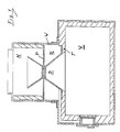
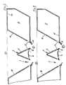
Fig. 1 zeigt eine bekannte Brennvorrichtung zum Verbrennen von Holz oder Kohle, bestehend aus einer Frontwand mit Brennstoff-Einfüllöffnung, zwei Seitenwänden, einer Rückwand, einer Bodenwand und einer Deckenwand, einer Tür, einem Regelelement zur Regelung einer Frischluft-Einlauföffnung und einer Trennwand T mit Durchtrittsöffnung zum Abschluß einer Vorbrennkammer V gegenüber einer Nachbrennkammer N. Dabei ist die Vorbrennkammer V unterhalb der Nachbrennkammer N angeordnet. An die Durchtrittsöffnung schließt abgedichtet eine von einem Ringraum R, der mit der Frischluft-Einlauföffnung in Verbindung steht, umgebene Düsenausbildung D an. Als Trennwand T dient eine der beiden Seitenwände, die Rückwand, die Bodenwand oder die Deckenwand. Am verjüngten Ende der Düsenausbildung D schließt unter Belassung eines Luftspalts eine Platte P quer an, die im Bereich des verjüngten Endes der Düsenausbildung D eine Öffnung aufweist. Zum außenseitigen Abschluß des Ringraums R dient ein die Platte P außenseitig umgebender Wandungskörper W, der an die Trennwand T abgedichtet anschließt und dessen von der Vorbrennkammer V aus gesehen jenseits der Platte P gelegener Teil innenseitig die Nachbrennkammer N bildet.Fig. 1 shows a known burning device for burning wood or coal, consisting of a front wall with fuel filler opening, two side walls, a rear wall, a bottom wall and a top wall, a door, a control element for controlling a fresh air inlet opening and a partition wall T. with a through opening for closing a pre-combustion chamber V with respect to an after-combustion chamber N. The pre-combustion chamber V is arranged below the after-combustion chamber N. A nozzle formation D, which is surrounded by an annular space R, which is connected to the fresh air inlet opening, adjoins the passage opening in a sealed manner. One of the two side walls, the rear wall, the bottom wall or the ceiling wall, serves as the partition wall T. At the tapered end of the nozzle formation D, a plate closes, leaving an air gap P across, which has an opening in the region of the tapered end of the nozzle formation D. For the outside closure of the annular space R is a wall body W surrounding the plate P on the outside, which connects to the partition wall T in a sealed manner and whose part, seen from the pre-combustion chamber V and beyond the plate P, forms the afterburner chamber N on the inside.
Eine solche oder ähnlich ausgebildete Brennvorrichtung gilt es durch die vorliegende Erfindung zu verbessern. Dabei spielt es keine Rolle, ob die Vorbrennkammer wie im dargestellten Fall unterhalb der Nachbrennkammer oder über, vor, neben oder hinter letzterer angeordnet ist.Such a or similarly designed burner device is to be improved by the present invention. It does not matter whether the pre-combustion chamber is arranged below the post-combustion chamber or above, in front of, next to or behind the latter, as in the case shown.
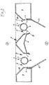
Bei der ersten Ausführungsform gemäß Fig. 2 sind im Bereich der Trennebene zwischen Vorbrennkammer 1 und Nachbrennkammer 2 gemäß zeichnerischer und beispielhafter Darstellung insgesamt fünf Düsenausbildungen 3 vorgesehen, wobei zwischen je zwei benachbarten Düsenausbildungen 3 ein Hohlkörper 4 angeordnet ist.In the first embodiment according to FIG. 2, a total of five
Die Anzahl der vorzusehenden Düsenausbildungen ist praktisch beliebig und hängt im Prinzip lediglich von der im Einzelfall gewünschten Heizleistung und damit von der für diese vorzusehenden Baugröße der Brennvorrichtung ab. Wesentlich für die Anzahl der Düsenausbildungen ist, daß bei der für eine bestimmte Heizleistung notwendigen Gesamt-Durchtrittsquerschnittsfläche die bei konstanter Länge der Düsenausbildungen infolge der mehreren Düsenausbildungen erreichbare Breite derselben nur so groß ist, daß eine intensive Mischung von Brenngas und Luft in den Düsenausbildungen bis ins Zentrum des durch die Düsenausbildungen hindurchgeführten Gasstroms möglich ist. Dies gilt für alle dargestellten und auch alle anderweitigen Ausführungsformen; im übrigen aber auch dazu, wenn mehrere Ausführungsformen miteinander kombiniert werden.The number of nozzle designs to be provided is practically arbitrary and in principle depends only on the heating output desired in the individual case and thus on the size of the combustion device to be provided for this. It is essential for the number of nozzle designs that, given the total passage cross-sectional area required for a specific heating output, the width of the nozzle designs that can be achieved with a constant length of the nozzle designs as a result of the plurality of nozzle designs is only so large that an intensive mixture of fuel gas and air in the nozzle designs is effective right up to the point Center of the gas flow passed through the nozzle formations is possible. This applies to all illustrated and also all other embodiments; otherwise also when several embodiments are combined.
Die Hohlkörper 4 sind des weiteren im Fall der ersten Ausführungsform zur Vorbrennkammer 1 hin aus einem teilkreisförmigen Element 5 und zur Nachbrennkammer 2 hin aus einem im wesentlichen flachen Element 6 gebildet, wobei jeweils zwischen den beiden Enden jedes teilkreisförmigen Elements 5 und dem gegenüberliegenden im wesentlichen flachen Element 6 ein Abstand zur Bildung einer Luftaustrittsöffnung 7 vorgesehen ist, die sich über die gesamte Länge der Hohlkörper 4 erstreckt. Die im wesentlichen flachen Elemente 6 sind an ihren beiden Enden zur Nachbrennkammer 2 hin umgebogen und bilden so mit den umgebogenen Verlängerungsflächenteilen 8 Führungs- und Leitflächen für aus dem Inneren der Hohlkörper 4 durch deren Luftaustrittsöffnungen 7 austretende sekundäre Verbrennungsluft.The
Links und rechts der insgesamt aus den fünf Düsenausbildungen 3 bestehenden Einheit sind jeweils Bereiche eines Luftkanals 9 erkennbar, der sich entlang aller vier Seiten erstrecken und als Ringkanal ausgebildet sein kann; dieser Luftkanal 9 bildet mit seinen beiden den jeweils benachbarten Hohlkörpern 4 zugewandten Wänden 10 im Bereich der Trennebene die jeweils außenseitige Begrenzung der zugehörigen Düsenausbildung 3. Analog zu den Luftaustrittsöffnungen 7 der Hohlkörper 4 sind auch in den eben genannten Wänden 10 und dabei in analoger Anordnung zu diesen weitere Luftaustrittsöffnungen 7 vorgesehen, die ebenfalls dem Austritt von sekundärer Verbrennungsluft dienen.To the left and right of the unit consisting of the five
Die Luftkanäle 9 können, wie mittels einer Wand 11 angedeutet ist, in Bereiche 9a und 9b unterteilt sein, die nicht miteinander in Verbindung stehen. Dabei dienen dann der Bereich 9a der Aufnahme sekundärer Verbrennungskluft und der Bereich 9b der Aufnahme primärer Verbrennungsluft, zu deren Weiterführung in Richtung auf die jeweils benachbarte Düsenausbildung 3 Luftaustrittsöffnungen 12 vorgesehen sind.The
Je nach dem in Fig. 2 nicht dargestellten Anschluß des Luftkanals 9 bzw. seiner Kanalbereiche 9a und 9b können letztere entgegen der vorstehenden Angabe zur Führung von Rauchgas bzw. Schwelgas bestimmt sein, das über die jeweils zugehörigen Luftaustrittsöffnungen 7 bzw. 12 in Richtung auf die jeweils benachbarte Düsenausbildung 3 abzugeben ist.Depending on the connection of the
Das vorstehend als im wesentlichen flaches Element 6 bezeichnete Teil der Hohlkörper 4 kann wie bei den beiden linken Hohlkörpern 4 dargestellt ein in der Tat nahezu exakt flaches Element sein; es kann aber auch wie bei den beiden in Fig. 2 rechten Hohlkörpern dargestellt ein Element sein, daß in Richtung auf das Innere der Hohlkörper 4 ausgebeult ist. Eine solche Ausbeulung dient in Verbindung mit den umgebogenen Verlängerungsflächenteilen 8 der Elemente 6 dazu, daß sich infolge des hinter den freien Kanten der umgebogenen Bereiche herrschenden Unterdrucks eine Wirbelausbildung einstellt, die die innige Durchmischung der Einzelbestandteile des durch die Düsenausbildungen 3 hindurchtretenden Gasstroms begünstigt.The part of the
Von den Luftkanälen 9 in den Bereich der Nachbrennkammer 2 geführte Flächenteile 13, die insbesondere als Blech gestaltet sein können, dienen durch ihre gegenseitig konvergierende Anordnung dazu, die Teilströme der einzelnen Düsenausbildungen 3 aufeinanderzu zu führen, so daß sich in bevorzugter Weise diese Ströme ggf. sogar in einem gemeinsamen Bereich treffen können und dort bei entsprechenden Mischverhältnissen der Gaskomponenten und entsprechender Temperatureinstellung eine sogenannte Feuerwalze bilden können, was einen äußerst günstigen Einfluß auf das Emissionsverhalten der Brennvorrichtung hat.Surface parts guided from the
Die im Bereich der Vorbrennkammer 1 gelegenen und den äußeren Düsenausbildungen 3 benachbarten Wände 10 des Luftkanals 9 sind in gegenseitiger Zuordnung divergierend angeordnet, um so eine Art Trichter für das eigentliche Brenngut zu bilden.The
Beachtenswert ist noch, daß die umgebogenen Verlängerungsflächenteile 8 der im wesentlichen flachen Elemente 6 der Hohlkörper 4 gegenüber den freien Enden der teilkreisförmigen Elemente 5 der Hohlkörper 4 etwas in Richtung auf das Zentrum der Hohlkörper 4 zurückgezogen sind, nämlich als Maßnahme zur Verhinderung einer Verschmutzung der Luftsaustrittsöffnungen 7.It is also worth noting that the bent-over
Die erste Ausführungsform gemäß Fig. 2 ist sowohl für eine Brennvorrichtung geeignet und bestimmt, bei der die Vorbrennkammer 1 oberhalb der Nachbrennkammer 2 angeordnet ist, als auch für eine Brennvorrichtung, bei der die Vorbrennkammer 1 vor, neben oder hinter der Nachbrennkammer 2 angeordnet ist. Im letztgenannten Fall sollten in Hinblick auf gute Emissionsverhältnisse die Hohlkörper 4 und damit die Düsenausbildungen 3 horizontal angeordnet sein, damit längstmöglich möglichst kein oder schlimmstenfalls ein möglichst kleiner Bereich der Düsenausbildungen 3 durch den sogenannten Glutstock nicht bedeckt und damit ein unmittelbares Durchbrennen von der Vorbrennkammer 1 zur Nachbrennkammer 2 hin verhindert ist.The first embodiment according to FIG. 2 is suitable and intended both for a combustion device in which the
Die zweite Ausführungsform gemäß Fig. 3 ist ebenfalls wie diejenige der Fig. 2 für praktisch jede relative Zuordnung der Vorbrennkammer 1 zur Nachbrennkammer 2 geeignet, obwohl sie bevorzugt geeignet ist für den Fall der Anordnung der Vorbrennkammer 1 oberhalb der Nachbrennkammer 2.The second embodiment according to FIG. 3 is also, like that of FIG. 2, suitable for practically any relative assignment of the
Die Ausführungsform der Fig. 3 zeigt zwei grundsätzlich unterschiedliche gestaltete Hohlkörper 4. Dabei sind die jeweils außen gelegenen Hohlkörper 4 aus zwei teilkreisförmigen Elementen aufgebaut, wobei das Element 5 in seiner wesentlichen Gestaltung dem Element 5 der Ausführungsform gemäß Fig. 2 entspricht. Das zweite Element 6 der Hohlkörper 4 ist in diesem Fall ebenfalls teilkreisförmig gestaltet, also grundsätzlich anders das zweite Element 6 der Ausführungsform gemäß Fig. 2 gestaltet. Der zentral gelegene Hohlkörper 4 ist in diesem Fall also als verhältnismäßig großer und hoher Hohlkörper ausgebildet, wobei das der Vorbrennkammer 1 zugewandte Element 5 ein etwa dreieckiges Element ist, dem gegenüber ein Element 6 angeordnet ist, das eine nicht unerhebliche Ähnlichkeit zu dem Element 6 der Ausführungsform gemäß Fig. 2 besitzt.The embodiment of FIG. 3 shows two fundamentally different designed
Bei beiden vorgenannten Arten von Hohlkörpern sind wieder Luftaustrittsschlitze 7 vorgesehen, während nur bei dem zentral gelegenen Hohlkörper 4 analog zu den Hohlkörpern 4 der ersten Ausführungsform Verlängerungsflächenteile 8 als Führungs- und Leitflächen vorgesehen sind.In both of the aforementioned types of hollow bodies,
Soweit im übrigen eine Übereinstimmung mit der ersten Ausführungsform gegeben ist, kann hier eine weitere Beschreibung der zweiten Ausführungsform entfallen.Insofar as there is otherwise agreement with the first embodiment, a further description of the second embodiment can be omitted here.
Auch die dritte Ausführungsform gemäß Fig. 4a bzw. Fig. 4b ist ebenfalls wie diejenigen der Fig. 2 bzw. Fig. 3 für praktisch jede relative Zuordnung von Vorbrennkammer 1 und Nachbrennkammer 2 geeignet, obwohl sie bevorzugt geeignet ist für den Fall der Anordnung der Vorbrennkammer 1 vor, hinter oder neben der Nachbrennkammer 2. Im letztgenannten Fall sollte die Anordnung eine solche sein, daß die Düsenausbildungen 3 bzw. Hohlkörper 4 vertikal verlaufen.The third embodiment according to FIGS. 4a and 4b, like those of FIGS. 2 and 3, is also suitable for practically any relative assignment of
Die Ausführungsform der Fig. 4a und 4b zeigt einen wiederum anders gestalteten Hohlkörper 4, nämlich einen solchen, der im Querschnitt die Gestalt eines gleichschenkligen und gegebenenfalls sogar gleichseitigen Dreiecks aufweist. Es besteht insofem eine gewisse Ähnlichkeit zur Gestaltung des zentralen Hohlkörpers 4 der zweiten Ausführungsform gemäß Fig. 3. Ebenso wie dies bei der ersten Ausführungsform gemäß Fig. 2 beschrieben worden ist, besteht auch hier die Möglichkeit der Zuführung von Schwelgas oder Rauchgas über den Luftkanal 9 neben der selbstverständlich gegebenen Möglichkeit der Zuführung sekundärer Verbrennungsluft. Die Zuführung von Schwelgas bzw. Rauchgas über den Luftkanal 9 hängt lediglich davon ab, ob solche Gase dem Kanal 9 zugeführt werden, wozu dieser beispielsweise wie in Fig. 2 intern unterteilt sein kann.The embodiment of FIGS. 4a and 4b shows a again differently designed
Für die Zuführung von Schwelgas wäre lediglich in der in der Zeichnung oberen Fläche des Luftkanals 9 eine Gaseintrittsmöglichkeit von der Vorbrennkammer 1 aus vorzusehen. Analog wäre für die Zuführung von Rauchgas zum Luftkanal 9 eine Zutrittsmöglichkeit in der in der Zeichnung unteren Wand des Luftkanals vorzusehen.For the supply of carbonization gas would only be in the top in the drawing Surface of the
Die Zuführung von Schwelgas aus der Vorbrennkammer 1 in den Luftkanal 9 kann je nach Bauweise der Brennvorrichtung bzw. der Relativzuordnung von Vorbrennkammer 1 zur Nachbrennkammer 2 eine solche sein, die die Entstehung des Schwelgases und dessen natürliches Bewegungsbestreben nutzt, um in den Luftkanal 9 zu gelangen. Für die Zuführung von Rauchgas in den Luftkanal 9 kann möglicherweise, und dabei wiederum in Abhängigkeit von der Gesamtgestaltung der Brennvorrichtung und der Relativzuordnung von Vorbrennkammer 1 zu Nachbrennkammer 2, gleiches gelten. Im übrigen kann die Zuführung von Rauchgas durch die oben schon näher beschriebenen Führungsbleche 13 begünstigt werden, hinter denen sich außenseitig ein Unterdruck ausbildet, der den zwischen den beiden einander gegenüberliegenden Führungsflächen 13 durchgehenden Gasstrom zu einer Wirbelbildung hinter den und zugleich seitlich der freien Enden der Führungsteile 13 veranlaßt. Die Wirbelbildung kann bei entsprechender Anordnung der Eintrittsöffnungen für Rauchgas zum Luftkanal 9 dazu genutzt werden, das Rauchgas praktisch zurückzuführen und zirkulieren zu lassen. Diese Möglichkeit besteht im übrigen bei allen dargestellten Ausführungsformen.The supply of carbonization gas from the
Die Ausführungsform der Fig. 5a und Fig. 5b zeigt einen wiederum etwas anders gestalteten Hohlkörper 4, nämlich einen solchen, der zwar eine gewisse Ähnlichkeit mit dem Hohlkörper 4 der Ausführungsform der Fig. 4a bzw. Fig. 4b hat, der jedoch im Querschnitt die Gestalt eines verhältnismäßig spitzwinkeligen gleichschenkeligen Dreiecks aufweist. Ebenso wie dies bei den zuvor beschriebenen Ausführungsformen angegeben worden ist, besteht auch hier die Möglichkeit der Zuführung von Schwelgas oder Rauchgas über den Luftkanal 9 neben bzw. zusätzlich zu der selbstverständlich gegebenen Möglichkeit der Zuführung sekundärer Verbrennungsluft. Die Zuführung von Schwelgas bzw. Rauchgas hängt auch in diesem Fall lediglich davon ab, ob solche Gase dem Kanal 9 zugeführt werden. Ist dies der Fall, so kann es sich bei dem Kanal um einen solchen handeln, der beispielsweise gemäß Fig. 2 intern unterteilt ist.The embodiment of FIGS. 5a and 5b shows a again slightly differently designed
Eine aus Fig. 5a ersichtliche wesentliche Unterschiedlichkeit zur Ausführungsform beispielsweise mit Fig. 4a besteht darin, daß der Luftkanal 9 hier nicht als Ringkanal ausgebildet ist; im rechten Teil der Fig. 5a ist ein Teil des Luftkanals 9 erkennbar, der sich unterhalb und oberhalb der Zeichnungsebene und parallel hierzu weiter erstreckt, um das Innere der Hohlkörper 4 dort anschließen zu können. In dem links in Fig. 5a gezeigten Bereich ist kein Teilelement des Luftkanals 9 vorgesehen. Dies macht auch die Darstellung der Fig. 5a deutlich erkennbar.An essential difference from FIG. 5a to the embodiment, for example with FIG. 4a, is that the
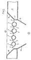
Fig. 6 zeigt eine Ausführungsform, deren Hohlkörper 4 eine gewisse Ähnlichkeit mit den jeweils links bzw. rechts gelegenen Hohlkörpern der Ausführungsform gemäß Fig. 3 zeigen. Auch in diesem Fall bestehen die Hohlkörpern aus zwei teilkreisförmigen Elementen 5 bzw. 6. Im linken Teil der Fig. 6 ist jedoch ein Fall dargestellt, bei dem die Innen- und Außenradien der teilkreisförmigen Elemente 5 größer als die Innen- bzw. Außenradien der teilkreisförmigen Elemente 6 sind. Durch die aus Fig. 6 ersichtliche Anordnung der teilkreisförmigen Elemente 5 und 6 sind die Luftaustrittsschlitze so angeordnet, daß sie durch von der Vorbrennkammer 1 aus durch die Düsenausbildungen 3 hindurchfallende Partikel nicht verstopft werden können, weil die Luftaustrittsschlitze 7 gegenüber der Fallrichtung zurückversetzt sind.FIG. 6 shows an embodiment, the
Bei den beiden im rechten Teil der Fig. 6 dargestellten Hohlkörpern besitzen die teilkreisförmigen Elemente 5 bzw. 6 dagegen im wesentlichen gleiche Innen- und Außendurchmesser; jedoch sind die freien Ränder der teilkreisförmigen Elemente 6 so gestaltet, daß sie parallel zur Durchtrittsrichtung durch die Düsenausbildung 3 verlaufen, und zwar ausgehend von den jeweiligen Eckpunkten der Innenflächen der teilkreisförmigen Elemente 6. Auch diese Ausbildung stellt sicher, daß eine Verstopfung der Luftaustrittsschlitze 7 durch herabfallende Partikel verhindert ist.In the case of the two hollow bodies shown in the right part of FIG. 6, the part-
Im rechten Teil der Fig. 6 ist wiederum der Luftkanal 9 ersichtlich, der über einen Luftaustrittsschlitz 7 mit der benachbarten Düsenausbildung 3 in Verbindung steht. Im linken Teil ist eine analoger Bereich bewußt nicht mit 9 bezeichnet, weil es sich bei diesem Bereich um einen solchen handeln kann, der nicht Bestandteil des Luftkanals 9 sein muß, wohl aber sein kann. Handelt es sich hierbei um einen Bestandteil des Luftkanals 9, so wäre analog zum rechten Teil der Fig. 7 ein Luftaustrittsschlitz 7 vorzusehen. Handelt es sich dagegen um einen anderen Luftkanal, beispielsweise um einen solchen, über den Schwel- und oder Rauchgas der Vorbrennkammer 1 bzw. der Nachbrennkammer 2 zuzuführen ist, so müßte zur Durchführung dieser Gaskomponenten ein entsprechender Gasaustrittsschlitz vorgesehen werden.In the right part of FIG. 6, the
Die exakte Darstellung im linken Teil der Fig. 6 zeigt also eigentlich den Fall, bei dem dem dort vorgesehenen Kanalteil keine funktionelle Bedeutung zukommt.The exact representation in the left part of FIG. 6 actually shows the case at the part of the duct provided there has no functional significance.
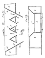
Die Ausführungsform der Fig. 7 betrifft den Fall der Anordnung der Vorbrennkammer 1 vor, neben oder hinter der Nachbrennkammer 2, und zwar mit Zuführung von Schwelgas über den Luftkanal 7 und den dort vorgesehenen Austrittsschlitz 7 zu der benachbarten Düsenausbildung 3. In diesem Fall ist an dem höchstgelegenen und zugleich der Vorbrennkammer 1 zugewandten Bereich des Luftkanals 9 eine Eintrittsöffnung 14 für Schwelgas vorgesehen. Man hat sich in diesem Fall den Einbau des dargestellten Teilbereichs der Brennvorrichtung zwischen der Vorbrennkammer 1 und der Nachbrennkammer 2 so vorzustellen, daß die Hohlkörper 4 horizontal verlaufen. Sollte aus irgendwelchen besonderen Gründen vorzusehen sein, daß die Hohlkörper 4 vertikal verlaufen, so wäre die Eintrittsöffnung 14 nicht nur am weitesten rechts gelegenen Teil des Luftkanals 9 gemäß Darstellung in Fig. 7 anzuordnen, sondern zugleich an dem oberhalb der Zeichnungsebene höchstgelegenen Bereich des Luftkanals 9.The embodiment of FIG. 7 relates to the case of the arrangement of the
Die Ausführungsform der Fig. 8 betrifft den Fall der Rückführung von Rauchgas, nämlich zunächst über die Eintrittsöffnung 15 in den Luftkanal 9 und dann von dort durch den Austrittsschlitz 7 in den Bereich der benachbarten Düsenausbildung 3. Bei diesem Rauchgas handelt es sich um solches, das nach Vorbeilaufen an dem freien Rand des Verlängerungsteils 13 infolge des hinter letzterem herrschenden Unterdrucks in den letztgenannten Bereich zurückgezogen wird und dort an sich zu einer Wirbelbildung neigt. Die Ausbildung der Eintrittöffnung 15 macht es jedoch möglich, daß zumindest ein erheblicher Teil des an der an sich sich einstellenden Wirbelbildung beteiligten Rauchgases in den Luftkanal 9 eintritt. Es kann hier also eine Zirkulation von Rauchgas stattfinden, die die Emissionsverhältnisse der Brennvorrichtung günstig beeinflußt.The embodiment of FIG. 8 relates to the case of the return of flue gas, namely first via the inlet opening 15 into the
Die erfindungsgemäße Brennvorrichtung zeichnet sich durch hervorragende Emissionsverhältnisse aus, wie sie bisher überhaupt nicht erreicht werden konnten, und zwar unabhängig von der Heizleistung und der zugehörigen Baugröße. Dabei sind die durch die mehreren Düsenausbildungen bereits erreichten äußerst günstigen Emissionsverhältnisse noch weiter verbesserbar durch die beschriebene besondere zusätzliche Schwel- und Rauchgasführung, die einen erheblichen Beitrag zur Verbesserung der Durchmischung der Brenngase und deren Abbrennen leisten.The combustion device according to the invention is distinguished by excellent emission ratios, which have not previously been possible, regardless of the heating power and the associated size. The extremely favorable emission ratios already achieved by the several nozzle designs can be further improved by the described additional smoldering and flue gas routing, which make a significant contribution to improving the mixing of the fuel gases and their burning.
Claims (16)
- An burning device for burning wood, coal or biomass, the interior of the device being divided up into a preburning chamber and an afterburning chamber, with several elongated nozzle formations (3) that are positioned essentially at right angles to their flow direction being provided in the area of the partition level between these chambers, the exteriors of these nozzle formations being at least partially surrounded by an airduct for secondary burning air which is closed towards the preburning chamber and the afterburning chamber and which has air outlet openings leading to the interior of the nozzle formations, two adjacent nozzle formations (3) each being separated from each other by a hollow body (4), the interior of all hollow bodies (4) being connected to the airduct (9) for air flow, and the hollow bodies (4) in the area of the partition level between the preburning chamber (1) and the afterburning chamber (2) being provided with air outlet openings (7).
- A device according to claim 1 characterized in that at least one hollow body (4) is at a continuously increasing distance at its surface facing the preburning chamber (1) at the cross-section of the hollow body's two logitudinal sides to its longitudinal median line from the level it shares with the nozzle formations (3) jointly formed by it and them.
- A device according to claim 2 characterized in that the surface (5) of at least one hollow body (4) which faces the preburning chamber (1) is in the shape of a partial circle, in particular of a semicircle, the center of which is located approximately in the area of the partition level.
- A device according to claim 2 or 3 characterized in that the surface (6) of at least one hollow body (4) which faces the afterburning chamber (2) is approximately in the shape of a partial circle, in particular of a semicircle, the center of which is located approximately in the area of the partition level.
- A device according to at least one of claims 1 to 4 characterized in that at least one hollow body (4) is at a continuously decreasing distance at its surface (6) facing the afterburning chamber (2) at the cross section of the hollow body's two logitudinal sides to its longitudinal median line from the level it shares with the nozzle formations (3) jointly formed by it and them.
- A device according to at least one of claims 1 to 4 characterized in that at least one hollow body (4) is at the same constant distance at its surface (6) facing the afterburning chamber (2) from the partition level between the preburning chamber (1 ) and the afterburning chamber (2).
- A device according to claim 1 characterized in that at least one hollow body (4) has a triangular shape cross-sectionally, with one side of the triangle extending approximately parallel to the partition level, and the opposite side of the triangle facing the preburning chamber (1).
- An burning device according to at least one of claims 1 to 7 characterized in that the air outlet openings (7) have the shape of slits and are located in the circumference area of the hollow bodies (4) which face both the afterburning chamber (2) and the nozzle formations (3).
- An burning device according to claim 8 characterized in that the air outlet slits are offset in the aforementioned circumference area of the hollow bodies (4) by 10° to 25° in relation to the level of the partition wall.
- A device according to at least one of the preceding claims characterized in that the air outlet openings (7) are essentially shaped as openings or slits positioned at a diagonal angle to the partition wall level and, at the same time, directed towards the afterburning chamber (2), and in that they are located in the circumference area of the hollow bodies (4) facing the afterburning chamber (2).
- A device according to claims 2 to 10 characterized in that the hollow bodies (4) are provided with short surface extension parts (8) that are oriented towards the afterburning chamber (2) and that have exposed ends.
- A device according to claim 1 characterized in that the nozzle formations (3) have, in the case of the preburning chamber (1) being placed above the afterburning chamber (2), a width of 6 mm to 12 mm, and, in the case of the preburning chamber (1) being placed in front of, behind or at the side of the afterburning chamber (2), a width of 8 mm to 22 mm.
- A device according to claim 1 characterized in that the hollow bodies (4) have a width of about 15 mm to about 90 mm.
- A device according to claim 1 characterized in that the ratio of the width of the hollow bodies (4) to the width of the nozzle formations (3) is within a range of 2.5 to 4.0.
- A device according to claim 1 characterized in that the opposite walls (10) of the airduct (9) adjacent to the two outermost nozzle formations (3) are shaped in such fashion that they diverge relative to each other from the partition level.
- An burning device according to claim 1 characterized in that surface parts (13) extending parallel to the nozzle formations (3) and converging towards each other are formed in the area of the airduct (9) that faces both the nozzle formations (3) and the afterburning chamber (2).
Priority Applications (4)
| Application Number | Priority Date | Filing Date | Title |
|---|---|---|---|
| EP93114347A EP0641969B1 (en) | 1993-09-07 | 1993-09-07 | Burning device for wood, coal and biomass |
| AT93114347T ATE134758T1 (en) | 1993-09-07 | 1993-09-07 | BURNING DEVICE FOR WOOD, COAL AND BIOMASS |
| DK93114347.3T DK0641969T3 (en) | 1993-09-07 | 1993-09-07 | Combustion device for wood, coal and biomass |
| DE59301743T DE59301743D1 (en) | 1993-09-07 | 1993-09-07 | Burning device for wood, coal and biomass |
Applications Claiming Priority (1)
| Application Number | Priority Date | Filing Date | Title |
|---|---|---|---|
| EP93114347A EP0641969B1 (en) | 1993-09-07 | 1993-09-07 | Burning device for wood, coal and biomass |
Publications (2)
| Publication Number | Publication Date |
|---|---|
| EP0641969A1 EP0641969A1 (en) | 1995-03-08 |
| EP0641969B1 true EP0641969B1 (en) | 1996-02-28 |
Family
ID=8213240
Family Applications (1)
| Application Number | Title | Priority Date | Filing Date |
|---|---|---|---|
| EP93114347A Expired - Lifetime EP0641969B1 (en) | 1993-09-07 | 1993-09-07 | Burning device for wood, coal and biomass |
Country Status (4)
| Country | Link |
|---|---|
| EP (1) | EP0641969B1 (en) |
| AT (1) | ATE134758T1 (en) |
| DE (1) | DE59301743D1 (en) |
| DK (1) | DK0641969T3 (en) |
Cited By (1)
| Publication number | Priority date | Publication date | Assignee | Title |
|---|---|---|---|---|
| CN101644429B (en) * | 2009-06-23 | 2011-04-20 | 宁波双翼能源科技有限公司 | Biomass furnace combustor and combustion method thereof |
Families Citing this family (2)
| Publication number | Priority date | Publication date | Assignee | Title |
|---|---|---|---|---|
| DE4435749C2 (en) * | 1994-10-06 | 1998-05-28 | Heribert Posch | Solid fuel heater |
| DE4435748C2 (en) * | 1994-10-06 | 1997-08-14 | Heribert Posch | Heater |
Family Cites Families (4)
| Publication number | Priority date | Publication date | Assignee | Title |
|---|---|---|---|---|
| DE3625151A1 (en) * | 1986-07-25 | 1988-01-28 | Hermann Hofmann | SOLID FUEL OVEN |
| DE3781987T2 (en) * | 1986-08-08 | 1993-03-11 | Clinton Badger Pike | OVEN. |
| DE4039387A1 (en) * | 1990-12-10 | 1992-06-11 | Heribert Posch | BURNING DEVICE FOR WOOD AND COAL |
| US5158025A (en) * | 1991-04-11 | 1992-10-27 | Johnson Theodore J | Waste fuel combustion system |
-
1993
- 1993-09-07 AT AT93114347T patent/ATE134758T1/en not_active IP Right Cessation
- 1993-09-07 DE DE59301743T patent/DE59301743D1/en not_active Expired - Lifetime
- 1993-09-07 EP EP93114347A patent/EP0641969B1/en not_active Expired - Lifetime
- 1993-09-07 DK DK93114347.3T patent/DK0641969T3/en active
Cited By (1)
| Publication number | Priority date | Publication date | Assignee | Title |
|---|---|---|---|---|
| CN101644429B (en) * | 2009-06-23 | 2011-04-20 | 宁波双翼能源科技有限公司 | Biomass furnace combustor and combustion method thereof |
Also Published As
| Publication number | Publication date |
|---|---|
| ATE134758T1 (en) | 1996-03-15 |
| DE59301743D1 (en) | 1996-04-04 |
| DK0641969T3 (en) | 1996-07-22 |
| EP0641969A1 (en) | 1995-03-08 |
Similar Documents
| Publication | Publication Date | Title |
|---|---|---|
| EP0363834B1 (en) | Burner, particularly a high-speed burner | |
| DE60102991T2 (en) | Burners with low NOx emissions and processes for burning liquid and gaseous fuels | |
| DE112006003642T5 (en) | burner device | |
| DE3521266A1 (en) | GRATE ROD FOR A FIRING GRATE OF A LARGE BURNER AND BURNING GRATE FOR THIS LARGE BURNER | |
| DE2536688A1 (en) | STOVE FOR BURNING COMBUSTIBLE EXHAUST GASES | |
| EP0641969B1 (en) | Burning device for wood, coal and biomass | |
| DE3633236C2 (en) | ||
| DE10010762A1 (en) | Atmospheric gas burner | |
| DE2363611B2 (en) | Series burners for gas-powered heating devices | |
| DE19507088B4 (en) | premix | |
| EP0798510A2 (en) | Heating boiler | |
| DE69833416T2 (en) | incinerator | |
| DE102011117950B4 (en) | Primary feed for a solid fuel heater and a method for creating a primary draw | |
| DE2345838A1 (en) | BURNER | |
| DE102017116529A1 (en) | burner | |
| EP0773404A2 (en) | Burner | |
| DE3113418C2 (en) | ||
| DE10237604B4 (en) | Afterburner with a burner | |
| DE2201310A1 (en) | Device for burning liquid fuels | |
| DE3503554C2 (en) | ||
| EP1091171B1 (en) | Method for the generation of a homogeneous air flow in a forced-draft burner and device for its realization | |
| AT397558B (en) | ATMOSPHERIC SERIES GAS BURNER | |
| DE19735345A1 (en) | Oil or gas blower burner with burner pipe with blast connection | |
| DE2242037C2 (en) | Tubular gas burner, especially for dryers | |
| DE4125226A1 (en) | Combustion tube for gas burner - has line of equally spaced outlets extending over entire length |
Legal Events
| Date | Code | Title | Description |
|---|---|---|---|
| PUAI | Public reference made under article 153(3) epc to a published international application that has entered the european phase |
Free format text: ORIGINAL CODE: 0009012 |
|
| 17P | Request for examination filed |
Effective date: 19940425 |
|
| AK | Designated contracting states |
Kind code of ref document: A1 Designated state(s): AT BE CH DE DK FR GB IT LI NL SE |
|
| RBV | Designated contracting states (corrected) |
Designated state(s): AT BE CH DE DK FR GB IT LI NL SE |
|
| 17Q | First examination report despatched |
Effective date: 19950516 |
|
| GRAH | Despatch of communication of intention to grant a patent |
Free format text: ORIGINAL CODE: EPIDOS IGRA |
|
| GRAA | (expected) grant |
Free format text: ORIGINAL CODE: 0009210 |
|
| AK | Designated contracting states |
Kind code of ref document: B1 Designated state(s): AT BE CH DE DK FR GB IT LI NL SE |
|
| PG25 | Lapsed in a contracting state [announced via postgrant information from national office to epo] |
Ref country code: NL Free format text: LAPSE BECAUSE OF FAILURE TO SUBMIT A TRANSLATION OF THE DESCRIPTION OR TO PAY THE FEE WITHIN THE PRESCRIBED TIME-LIMIT Effective date: 19960228 Ref country code: GB Effective date: 19960228 Ref country code: BE Effective date: 19960228 |
|
| REF | Corresponds to: |
Ref document number: 134758 Country of ref document: AT Date of ref document: 19960315 Kind code of ref document: T |
|
| REF | Corresponds to: |
Ref document number: 59301743 Country of ref document: DE Date of ref document: 19960404 |
|
| ITF | It: translation for a ep patent filed |
Owner name: JACOBACCI & PERANI S.P.A. |
|
| PG25 | Lapsed in a contracting state [announced via postgrant information from national office to epo] |
Ref country code: SE Effective date: 19960531 |
|
| ET | Fr: translation filed | ||
| REG | Reference to a national code |
Ref country code: CH Ref legal event code: NV Representative=s name: HIEBSCH & PEEGE AG PATENTANWAELTE |
|
| REG | Reference to a national code |
Ref country code: DK Ref legal event code: T3 |
|
| NLV1 | Nl: lapsed or annulled due to failure to fulfill the requirements of art. 29p and 29m of the patents act | ||
| GBV | Gb: ep patent (uk) treated as always having been void in accordance with gb section 77(7)/1977 [no translation filed] |
Effective date: 19960228 |
|
| PLBE | No opposition filed within time limit |
Free format text: ORIGINAL CODE: 0009261 |
|
| STAA | Information on the status of an ep patent application or granted ep patent |
Free format text: STATUS: NO OPPOSITION FILED WITHIN TIME LIMIT |
|
| 26N | No opposition filed | ||
| PGFP | Annual fee paid to national office [announced via postgrant information from national office to epo] |
Ref country code: DK Payment date: 20000930 Year of fee payment: 8 |
|
| PGFP | Annual fee paid to national office [announced via postgrant information from national office to epo] |
Ref country code: FR Payment date: 20010330 Year of fee payment: 8 |
|
| PGFP | Annual fee paid to national office [announced via postgrant information from national office to epo] |
Ref country code: AT Payment date: 20010331 Year of fee payment: 8 |
|
| PGFP | Annual fee paid to national office [announced via postgrant information from national office to epo] |
Ref country code: CH Payment date: 20010402 Year of fee payment: 8 |
|
| PG25 | Lapsed in a contracting state [announced via postgrant information from national office to epo] |
Ref country code: AT Free format text: LAPSE BECAUSE OF NON-PAYMENT OF DUE FEES Effective date: 20010907 |
|
| PG25 | Lapsed in a contracting state [announced via postgrant information from national office to epo] |
Ref country code: LI Free format text: LAPSE BECAUSE OF NON-PAYMENT OF DUE FEES Effective date: 20010930 Ref country code: CH Free format text: LAPSE BECAUSE OF NON-PAYMENT OF DUE FEES Effective date: 20010930 |
|
| PG25 | Lapsed in a contracting state [announced via postgrant information from national office to epo] |
Ref country code: DK Free format text: LAPSE BECAUSE OF NON-PAYMENT OF DUE FEES Effective date: 20011031 |
|
| REG | Reference to a national code |
Ref country code: CH Ref legal event code: PL |
|
| PG25 | Lapsed in a contracting state [announced via postgrant information from national office to epo] |
Ref country code: FR Free format text: LAPSE BECAUSE OF NON-PAYMENT OF DUE FEES Effective date: 20020531 |
|
| REG | Reference to a national code |
Ref country code: DK Ref legal event code: EBP |
|
| REG | Reference to a national code |
Ref country code: FR Ref legal event code: ST |
|
| PG25 | Lapsed in a contracting state [announced via postgrant information from national office to epo] |
Ref country code: IT Free format text: LAPSE BECAUSE OF NON-PAYMENT OF DUE FEES;WARNING: LAPSES OF ITALIAN PATENTS WITH EFFECTIVE DATE BEFORE 2007 MAY HAVE OCCURRED AT ANY TIME BEFORE 2007. THE CORRECT EFFECTIVE DATE MAY BE DIFFERENT FROM THE ONE RECORDED. Effective date: 20050907 |
|
| PGFP | Annual fee paid to national office [announced via postgrant information from national office to epo] |
Ref country code: DE Payment date: 20100929 Year of fee payment: 18 |
|
| PG25 | Lapsed in a contracting state [announced via postgrant information from national office to epo] |
Ref country code: DE Free format text: LAPSE BECAUSE OF NON-PAYMENT OF DUE FEES Effective date: 20120403 |
|
| REG | Reference to a national code |
Ref country code: DE Ref legal event code: R119 Ref document number: 59301743 Country of ref document: DE Effective date: 20120403 |