EP0641903A1 - Sectional false floor - Google Patents
Sectional false floor Download PDFInfo
- Publication number
- EP0641903A1 EP0641903A1 EP94112485A EP94112485A EP0641903A1 EP 0641903 A1 EP0641903 A1 EP 0641903A1 EP 94112485 A EP94112485 A EP 94112485A EP 94112485 A EP94112485 A EP 94112485A EP 0641903 A1 EP0641903 A1 EP 0641903A1
- Authority
- EP
- European Patent Office
- Prior art keywords
- plates
- plate
- raised floor
- floor according
- base
- Prior art date
- Legal status (The legal status is an assumption and is not a legal conclusion. Google has not performed a legal analysis and makes no representation as to the accuracy of the status listed.)
- Withdrawn
Links
Images


Classifications
-
- E—FIXED CONSTRUCTIONS
- E04—BUILDING
- E04F—FINISHING WORK ON BUILDINGS, e.g. STAIRS, FLOORS
- E04F15/00—Flooring
- E04F15/02—Flooring or floor layers composed of a number of similar elements
- E04F15/024—Sectional false floors, e.g. computer floors
- E04F15/02405—Floor panels
Definitions
- the invention relates to a raised floor with a multiplicity of base plates, each of which is supported in the region of its corners by means of supports on a solid base, a cavity being formed between the underside of the base plates and the base, according to the preamble of patent claim 1.
- the boards usually consist of a particle board or a metal tub filled with anhydrite.
- Four of these plates each meet at their corners in the area of the support surfaces on the supports and two of these plates each meet in the area of their edges.
- the edge surfaces of the plates are usually bevelled so that a gap with a V-shaped cross-section is open towards the bottom, while the plates are closed as evenly as possible Surface in the area of their upper edges touching each other directly.
- the base plates are designed alternately in the manner of a checkerboard pattern as base plates and top plates, the base plates having a closed or interrupted circumferential flange-like shoulder projecting essentially in the plate plane on their side facing the surface.
- the edge area of the lower plate therefore essentially has a cross section in the area of the shoulder L-shaped shape. The top panels with their edge areas can then be placed on this shoulder.
- the gap between two adjacent plates no longer extends linearly from the floor surface to the substrate or to the cavity under the raised floor, but is covered down to the cavity by the flange-like heel of the base plate.
- the fire is reliably prevented from penetrating through the gap or at least significantly delayed in comparison with the prior art, and on the other hand a seal against flue gases which is significantly improved compared to the prior art is achieved.
- the sealing of the joints between the floor panels plays a decisive role.
- the leak rate that is to say the air escaping through the separating joints, in the double floor of the invention is considerably reduced by covering the gap in comparison with the known floors.
- This seal can be further improved, for example, by providing appropriate sealing means on the shoulders in the contact area of the top plates.
- Another advantage of the double floor of the invention is that the mechanical strength of both the lower plates and the upper plates and thus the entire double floor in the area of the edges is considerably improved, since on the one hand the lower plates are stiffened even in the edge area by the L-shaped edge profile and on the other hand the top plates are no longer supported only in the area of the corners, but lie essentially over the entire length of the edge on the flange-like heel of the bottom plates.
- This allows the use of thinner panels and / or panels made of a material of lower strength, which can significantly reduce the manufacturing costs of the raised floor.
- the lower plates consist of fire-retardant or fire-resistant material at least in the area of the heel, i.e. in the area of the area critical to fire protection, or at least in this area have a fire-retardant or fire-resistant material Coating on.
- fire-retardant or fireproofing of the entire underside of the lower and / or upper plate facing the cavity is also entirely possible.
- the flange-like shoulder formed or arranged on the lower plate can, for example, be integrally formed on the lower plate, for example by milling the area of the lower plate located above the shoulder.
- the lower plate has a closed or interrupted peripheral frame, in particular profile frame, on its underside, which protrudes at least in regions on the peripheral sides of the lower plate and thus forms the shoulder.
- the frame can consist of the same material as the lower plate and is positively and / or non-positively, for example by gluing or stapling, connected to the underside of the lower plate.
- the lower plate is provided on its underside with a sheet metal which completely or partially covers the underside, as a result of which the fire protection properties in particular are considerably improved.
- the sheet metal protrudes above it and is bent in this area to an open, for example downwardly open to the cavity U-shaped, or closed, for example rectangular, square or triangular shaped rigid profile. This profile forms the shoulder for receiving the top plates and for covering the gap or the separating joint between adjacent plates.
- a further possibility of producing the shoulder on the lower plate is that the lower plates are made in two parts.
- Each base plate has a base plate, which is connected essentially concentrically on its underside to a second plate, the second plate being larger than the base plate.
- “Concentric” in this context means that both plates are essentially complementary to one another and arranged in such a way that the second plate on the peripheral sides or edges of the base plate protrudes substantially uniformly on all sides thereof and thus forms the circumferential shoulder.
- the top plate and the base plate of the bottom plate are preferably of essentially the same design, that is to say in particular with the same dimensions and made of the same material. This results in a particularly simple and cost-effective production of the base plates due to the number of different basic structural elements limited to the absolutely necessary minimum and thus the tools and devices necessary for the production.
- the second plate can be made of the same material as the base plate of the lower plate.
- at least the second plate of the lower plate preferably consists entirely of a fire-retardant or refractory material, in particular gypsum fiber material. This significantly improves fire safety not only in the area of the heel and thus the gap or the separating joint between two adjacent panels, but in the area of the entire area of the lower panel.
- connection of the base plate and the lower plate can in principle be made by any joining method, as long as a mutual slipping or shifting of the two plates against each other is reliably excluded.
- the base plate and the second plate of the lower plate are preferably connected in a form-fitting manner, in particular by nailing, stapling or the like, or in a force-fitting manner. especially by gluing or a combination of these joining processes.
- a structure-borne sound and / or temperature-insulating material preferably in the form of a thermoplastic film, is introduced between the base plate of the lower plate and the second plate , that is in particular inserted or glued.
- Another way to improve the impact sound insulation of the raised floor of the invention is to arrange a damper element between the plate of the supports and the floor panels in the area of the bearing surfaces of the floor panels, especially the base panels on the supports arranged at the corner points of the floor panels.
- a damper element between the plate of the supports and the floor panels in the area of the bearing surfaces of the floor panels, especially the base panels on the supports arranged at the corner points of the floor panels.
- either the surfaces of the support plates of the supports that support the base plates or the surface areas of the base plates lying opposite them are provided with a structure-borne sound-insulating covering or damping element, for example in the form of a separately manufactured insert, in particular made of an elastomer, for example rubber.
- damping coverings or damping elements When using such damping coverings or damping elements, they preferably have nubs or stop and / or centering elements projecting downward from their main plane in the area in which no lower plates lie directly, or in the case of a damping covering on the underside of the base plates.
- These knobs or stop and / or centering elements are designed in such a way that the top plates, supported by rubber, can be supported directly on the supports in addition to being supported on the flange-like heel of the bottom plates, with the base plates being fixed in the raised floor level simultaneously or alternatively by the radial surfaces of these elements he follows. This in particular facilitates the assembly of the raised floor according to the invention.
- a further ease of assembly can be achieved according to a further embodiment of the invention in that the lateral peripheral or edge surfaces of the base plates are beveled at least slightly wedge-shaped towards the ground in a manner known per se, so that there is a downward between each two adjacent base plates V-shaped opening gap results. This facilitates the insertion of the top plates into the free fields between four finished or assembled bottom plates.
- the heel in the area of the corners of the lower plate is preferably bevelled substantially diagonally with respect to the plane of the plate, so that the lower plates or the base plates of the lower plates in Touch the area of the corners of the shoulder to each other or lie opposite each other with a small distance, the corners of the plates facing each other in the upper edge area of the adjacent sub-plates lying directly against one another.
- the top plates preferably have such a shape and size that there is an essentially closed, flat surface of the raised floor in each case with the top plates inserted between the immediately adjacent bottom plates.
- the lower plates can be placed loosely on the supports or the plates of the supports.
- the sub-plates are attached to the supports and / or the supports on the subsurface in a positive and / or non-positive manner, for example by gluing, screwing , Stapling or the like.
- the top plates can be attached to the shoulders of the bottom plates.
- At least the top plates can be removed individually from the bottom plates, so that at least the gaps between each four bottom plates are freely accessible from above.
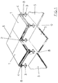
- the section shown in Fig. 1 from a double floor structure according to the invention has a number of vertically adjustable supports 3, which are regularly arranged on a solid surface so that they form the corner points of a square grid.
- an upper plate 5 is arranged in such a way that an overall checkerboard-like pattern of upper plates 5 and lower plates 1 results with a closed and flat surface.
- the lower plates 1 are designed in two parts and consist of a base plate 6 which is glued to a second plate 7 on its underside, that is to say toward the cavity under the raised floor side.
- the second plate 7 is, like the base plate 6, square, but the second plate 7 has a greater edge length than the base plate 6 and thus a larger area.
- the two plates 6, 7 are arranged concentrically to one another, so that the second plate 7 protrudes evenly over the edges of the base plate 6 in the region of all edges, which results in a flange-like, closed, circumferential shoulder 8 with an L-shaped cross section.
- the top plates 5 are placed on this shoulder 8 to form the raised floor, the thickness of the top plates 5 corresponding exactly to the thickness of the base plates 6.
- the second plates 7 of the sub-plates 1 are diagonally beveled in such a way that when the beveled edge regions 9 of the second plates 7 lie against or against one another in the assembled state, the upper corner or edge points 10 just touch ( Fig. 1 and Fig. 5).
- both the lower plates 1 or the base plates 6 and the upper plates 5 have a wedge-shaped bevel 11, so that, as can be seen in particular in FIGS. 5 and 6, a downward V -shaped opening gap or a parting line 12 results.
- this parting line 12 is completely covered by the shoulder 8 in the area of the edges and additionally by the plate 4 of the supports 3 in the area of the corners 2, which results in significantly improved fire safety overall.
- the lower plates 1 or the second plates 7 of the lower plates 1 lie directly on the plates 4 of the supports 3, while the upper plates 5 rest primarily on the shoulders 8 of the lower plates 1 and are therefore only indirectly supported on the supports 3.
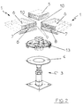
- a damper element 13 is arranged on the plate 4 of the support 3.
- This damper element 13 is made of rubber and has a flat disc-shaped area 14 which essentially covers the entire surface of the plate 4 and, when the lower plates 1 are placed on the supports, causes the actual damping between the plate 4 and the lower plate 1.
- Holding areas 15 are formed on the circumference of the damper element 13, which grip around the plate 4 in some areas and thus secure the damper element 13 against slipping.
- the damper element 13 has projecting stop axially with respect to the longitudinal axis of the support 3. or centering elements 16. These serve on the one hand to fix the position of the lower plates 1 in the floor plane when installing the raised floor according to the invention and on the other hand as additional dampers for the upper plates 5 placed on the heels 8, the axial height of these stop or centering elements 16 being at least slightly greater than the height of the flange-like shoulders 8.
- the embodiment shown in Fig. 3 differs from the embodiment of FIG. 2 essentially in that the lower plate 1 does not consist of a base plate 6 and a second plate 7, but that instead of the second plate 7 a closed peripheral profile frame 17 on the Bottom of the base plate 6 is arranged in the plate plane protrudes on all sides over the edge areas of the base plate 6 and thus forms the paragraph 8 for supporting the top plates 5.
Abstract
Description
Die Erfindung betrifft einen Doppelboden mit einer Vielzahl von Bodenplatten, die jeweils im Bereich ihrer Ecken mittels Stützen auf einem festen Untergrund gelagert sind, wobei zwischen der Unterseite der Bodenplatten und dem Untergrund ein Hohlraum gebildet wird, nach dem Oberbegriff des Patentanspruchs 1.The invention relates to a raised floor with a multiplicity of base plates, each of which is supported in the region of its corners by means of supports on a solid base, a cavity being formed between the underside of the base plates and the base, according to the preamble of
Bei den bekannten gattungsgemäßer Doppelböden sind sämtliche Platten im wesentlichen gleich ausgebildet. Die Platten bestehen üblicherweise aus einer Spanplatte oder aus einer Metallwanne, die mit Anhydrit gefüllt ist. Jeweils vier dieser Platten stoßen an ihren Ecken im Bereich der Auflageflächen auf den Stützen und jeweils zwei dieser Platten im Bereich ihrer Kanten aneinander. Dadurch ergibt sich zwischen jeweils zwei benachbarten Platten ein im Kantenbereich verlaufender durchgehender Spalt, dessen Breite primär von der Fertigungsgenauigkeit der Platten und sekundär von den beim Verlegen des Doppelbodens notwendigerweise in Kauf zu nehmenden Toleranzen bestimmt wird. Um die Toleranzen beim Verlegen möglichst gering halten zu können und das Verlegen zu erleichtern, sind die Kantenflächen der Platten üblicherweise so abgeschrägt, daß sich ein im Querschnitt V-förmiger nach unten zum Boden offener Spalt ergibt, während die Platten zur Erzielung einer möglichst gleichmäßig geschlossenen Oberfläche im Bereich ihrer Oberkanten unmittelbar sich berührend aneinanderliegen.In the known generic double floors, all plates are essentially the same. The boards usually consist of a particle board or a metal tub filled with anhydrite. Four of these plates each meet at their corners in the area of the support surfaces on the supports and two of these plates each meet in the area of their edges. This results in a continuous gap running in the edge area between each two adjacent panels, the width of which is determined primarily by the manufacturing accuracy of the panels and secondarily by the tolerances that are necessarily accepted when laying the raised floor. In order to keep the tolerances during installation as low as possible and to facilitate installation, the edge surfaces of the plates are usually bevelled so that a gap with a V-shaped cross-section is open towards the bottom, while the plates are closed as evenly as possible Surface in the area of their upper edges touching each other directly.
Im Hinblick auf die Verlegegenauigkeit und damit auf die ästhetischen Qualität insbesondere einer geschlossenen Oberfläche sind die bekannten Doppelböden durchaus zufriedenstellend. Nachteilig sowohl bei der Verwendung von Spanplatten als auch bei der Verwendung von mit Anhydrit gefüllten Wannen ist jedoch vor allem, daß sich aufgrund des von der Oberfläche des Bodens zum Untergrund durchgehenden insbesondere V-förmigen Spaltes die Anforderungen an eine ausreichende Brandschutzsicherheit nicht erfüllen lassen, da bei einem Brand im Hohlraum zwischen Doppelboden und Untergrund trotz ausreichender Brandschutzsicherheit der Platten selbst das Feuer und die Rauchgase bereits nach kurzer Zeit durch den Spalt dringen.With regard to the laying accuracy and thus the aesthetic quality, especially of a closed surface the well-known raised floors are quite satisfactory. A disadvantage of both the use of chipboard and the use of tubs filled with anhydrite is, above all, that due to the continuous V-shaped gap from the surface of the floor to the subsurface, the requirements for adequate fire safety cannot be met, since in the event of a fire in the cavity between the raised floor and the subsurface, even if the panels are sufficiently fire-proof, the fire and the flue gases can pass through the gap after a short time.
Ein weiterer Nachteil der bekannten Doppelböden ist, daß gerade im Bereich der stärksten auftretenden Belastung, nämlich im Bereich der Kanten, keine mechanische Unterstützung erfolgt, so daß die Platten auf diese schwächste Stelle hin ausgelegt werden müssen. Dies bedeutet, daß sämtliche Bodenplatten entsprechend stark dimensioniert und/oder aus einem hochfesten Material, beispielsweise hochverdichteter Spanplatte, hergestellt werden müssen. Dadurch werden die Herstellungskosten signifikant verteuert.Another disadvantage of the known raised floors is that there is no mechanical support precisely in the area of the heaviest load, namely in the area of the edges, so that the plates have to be designed for this weakest point. This means that all floor panels must be appropriately dimensioned and / or made from a high-strength material, for example highly compressed particle board. This significantly increases the cost of production.
Ausgehend von diesem Stand der Technik ist es die Aufgabe der vorliegenden Erfindung, einen Doppelboden der eingangs genannten Art zu schaffen, der eine erhöhte Brandschutzsicherheit aufweist und preiswert und einfach herzustellen ist.Based on this prior art, it is the object of the present invention to provide a raised floor of the type mentioned at the outset, which has increased fire safety and is inexpensive and easy to manufacture.
Diese Aufgabe wird durch einen Doppelboden nach der Lehre des Patentanspruchs 1 gelöst.This object is achieved by a raised floor according to the teaching of
Vorteilhafte Ausgestaltungen der Erfindung sind Gegenstand der Unteransprüche.Advantageous embodiments of the invention are the subject of the dependent claims.
Gemäß der Erfindung sind die Bodenplatten alternierend nach Art eines Schachbrettmusters als Unterplatten und Oberplatten ausgebildet, wobei die Unterplatten an ihrer zum Untergrund weisenden Seite einen geschlossen oder unterbrochen umlaufenden flanschartig im wesentlichen in der Plattenebene vorspringenden Absatz aufweisen. Der Kantenbereich der Unterplatte weist also im Bereich des Absatzes im Querschnitt eine im wesentlichen L-förmige Gestalt auf. Auf diesen Absatz sind dann die Oberplatten mit ihren Kantenbereichen auflegbar.According to the invention, the base plates are designed alternately in the manner of a checkerboard pattern as base plates and top plates, the base plates having a closed or interrupted circumferential flange-like shoulder projecting essentially in the plate plane on their side facing the surface. The edge area of the lower plate therefore essentially has a cross section in the area of the shoulder L-shaped shape. The top panels with their edge areas can then be placed on this shoulder.
Dies bedeutet, daß der zwischen zwei benachbarten Platten befindliche Spalt sich gemäß der Erfindung nun nicht mehr linear von der Bodenoberfläche zum Untergrund bzw. zum Hohlraum unter dem Doppelboden erstreckt, sondern nach unten zum Hohlraum durch den flanschartigen Absatz der Unterplatte abgedeckt wird. Dadurch wird bei einem Brand unterhalb des Doppelbodens zum einen ein Durchschlagen des Feuers durch den Spalt zuverlässig vermieden oder zumindest im Vergleich zum Stand der Technik signifikant verzögert und zum anderen eine gegenüber dem Stand der Technik wesentlich verbesserte Abdichtung gegen Rauchgase erzielt.This means that, according to the invention, the gap between two adjacent plates no longer extends linearly from the floor surface to the substrate or to the cavity under the raised floor, but is covered down to the cavity by the flange-like heel of the base plate. In the event of a fire below the raised floor, on the one hand, the fire is reliably prevented from penetrating through the gap or at least significantly delayed in comparison with the prior art, and on the other hand a seal against flue gases which is significantly improved compared to the prior art is achieved.
Insbesondere wenn der unter dem Doppelboden befindliche Hohlraum zur Belüftung bzw. Luftführung, beispielsweise im Zusammenwirken mit einer Raumklimaanlage, verwendet wird, spielt die Abdichtung der Trennfugen zwischen den Bodenplatten eine entscheidende Rolle. Auch bei diesem Anwendungsfall wird beim Doppelboden der Erfindung gegenüber den bekannten Böden die Leckrate, das heißt die durch die Trennfugen entweichende Luft, bereits durch die Abdeckung des Spalts erheblich reduziert. Diese Abdichtung kann beispielsweise noch dadurch weiter verbessert werden, daß im Auflagebereich der Oberplatten auf den Absätzen entsprechende Dichtmittel vorgesehen werden.Especially when the cavity located under the raised floor is used for ventilation or air guidance, for example in cooperation with a room air conditioning system, the sealing of the joints between the floor panels plays a decisive role. In this application, too, the leak rate, that is to say the air escaping through the separating joints, in the double floor of the invention is considerably reduced by covering the gap in comparison with the known floors. This seal can be further improved, for example, by providing appropriate sealing means on the shoulders in the contact area of the top plates.
Ein weiterer Vorteil des Doppelbodens der Erfindung besteht darin, daß die mechanische Festigkeit sowohl der Unterplatten als auch der Oberplatten und damit des gesamten Doppelbodens im Bereich der Kanten erheblich verbessert wird, da zum einen die Unterplatten durch das L-förmige Kantenprofil selbst im Kantenbereich versteift werden und zum anderen die Oberplatten nicht mehr nur im Bereich der Ecken unterstützt werden, sondern im wesentlichen über die gesamte Kantenlänge auf dem flanschartigen Absatz der Unterplatten aufliegen. Dadurch ist die Verwendung dünnerer Platten und/oder von Platten aus einem Material geringerer Festigkeit möglich, wodurch die Herstellungskosten des Doppelbodens erheblich gesenkt werden können.Another advantage of the double floor of the invention is that the mechanical strength of both the lower plates and the upper plates and thus the entire double floor in the area of the edges is considerably improved, since on the one hand the lower plates are stiffened even in the edge area by the L-shaped edge profile and on the other hand the top plates are no longer supported only in the area of the corners, but lie essentially over the entire length of the edge on the flange-like heel of the bottom plates. This allows the use of thinner panels and / or panels made of a material of lower strength, which can significantly reduce the manufacturing costs of the raised floor.
Um insbesondere die Brandschutzeigenschaften des Doppelbodens weiter zu verbessern, bestehen gemäß einem Ausführungsbeispiel der Erfindung die Unterplatten zumindest im Bereich des Absatzes, das heißt im Bereich des hinsichtlich des Brandschutzes kritischen Bereichs, aus feuerhemmendem oder feuerfestem Material oder weisen zumindest in diesem Bereich eine feuerhemmende oder feuerfeste Beschichtung auf. Selbstverständlich ist auch eine feuerhemmende oder feuerfeste Ausrüstung der gesamten zum Hohlraum weisenden Unterseite der Unter- und/oder Oberplatte durchaus möglich.In order to further improve, in particular, the fire protection properties of the raised floor, according to one exemplary embodiment of the invention, the lower plates consist of fire-retardant or fire-resistant material at least in the area of the heel, i.e. in the area of the area critical to fire protection, or at least in this area have a fire-retardant or fire-resistant material Coating on. Of course, fire-retardant or fireproofing of the entire underside of the lower and / or upper plate facing the cavity is also entirely possible.
Der an der Unterplatte ausgebildete bzw. angeordnete flanschartige Absatz kann beispielsweise einstückig an die Unterplatte angeformt sein, beispielsweise dadurch, daß der oberhalb des Absatzes befindliche Bereich der Unterplatte abgefräst wird. Nach einem Ausführungsbeispiel der Erfindung jedoch weist die Unterplatte an ihrer Unterseite einen geschlossen oder unterbrochen umlaufenden Rahmen, insbesondere Profilrahmen, auf, der an den Umfangsseiten der Unterplatte zumindest bereichsweise über diese hervorragt und so den Absatz bildet. Der Rahmen kann dabei aus demselben Material wie die Unterplatte bestehen und ist form- und/oder kraftschlüssig, beispielsweise durch Kleben oder Heften, mit der Unterseite der Unterplatte verbunden.The flange-like shoulder formed or arranged on the lower plate can, for example, be integrally formed on the lower plate, for example by milling the area of the lower plate located above the shoulder. According to an embodiment of the invention, however, the lower plate has a closed or interrupted peripheral frame, in particular profile frame, on its underside, which protrudes at least in regions on the peripheral sides of the lower plate and thus forms the shoulder. The frame can consist of the same material as the lower plate and is positively and / or non-positively, for example by gluing or stapling, connected to the underside of the lower plate.
Nach einem weiteren Ausführungsbeispiel der Erfindung ist die Unterplatte an ihrer Unterseite mit einem die Unterseite ganz oder bereichsweise abdeckenden Blech versehen, wodurch insbesondere die Brandschutzeigenschaften erheblich verbessert werden. An den Umfangsseiten bzw. Kanten der Unterplatte ragt das Blech über diese hervor und ist in diesem Bereich zu einem offenen, beispielsweise nach unten zum Hohlraum U-förmig offenen, oder geschlossenen, beispielsweis im Querschnitt rechteckig, quadratisch oder dreieckig geformten formsteifen Profil abgekantet. Dabei wird durch dieses Profil der Absatz zur Aufnahme der Oberplatten und zur Abdeckung des Spaltes bzw. der Trennfuge zwischen jeweils benachbarten Platten gebildet.According to a further exemplary embodiment of the invention, the lower plate is provided on its underside with a sheet metal which completely or partially covers the underside, as a result of which the fire protection properties in particular are considerably improved. On the circumferential sides or edges of the lower plate, the sheet metal protrudes above it and is bent in this area to an open, for example downwardly open to the cavity U-shaped, or closed, for example rectangular, square or triangular shaped rigid profile. This profile forms the shoulder for receiving the top plates and for covering the gap or the separating joint between adjacent plates.
Eine weitere Möglichkeit, den Absatz an der Unterplatte herzustellen besteht gemäß einem besonders bevorzugten Ausführungsbeispiel der Erfindung darin, daß die Unterplatten zweiteilig ausgeführt sind. Dabei weist jede Unterplatte jeweils eine Grundplatte auf, die an ihrer Unterseite mit einer zweiten Platte im wesentlichen konzentrisch verbunden ist, wobei die zweite Platte größer als die Grundplatte ist. "Konzentrisch" bedeutet dabei in diesem Zusammenhang, daß beide Platten im wesentlichen formkomplementär und so zueinander angeordnet sind, daß die zweite Platte an den Umfangsseiten bzw. Kanten der Grundplatte über diese an allen Seiten im wesentlichen gleichmäßig hervorragt und so den umlaufenden Absatz bildet.According to a particularly preferred embodiment of the invention, a further possibility of producing the shoulder on the lower plate is that the lower plates are made in two parts. Each base plate has a base plate, which is connected essentially concentrically on its underside to a second plate, the second plate being larger than the base plate. "Concentric" in this context means that both plates are essentially complementary to one another and arranged in such a way that the second plate on the peripheral sides or edges of the base plate protrudes substantially uniformly on all sides thereof and thus forms the circumferential shoulder.
Vorzugsweise sind bei diesem Ausführungsbeispiel die Oberplatte und die Grundplatte der Unterplatte im wesentlichen gleich ausgebildet, das heißt insbesondere mit gleichen Abmessungen und aus demselben Material. Dadurch ergibt sich eine besonders einfache und kostengünstige Herstellung der Bodenplatten aufgrund einer auf das absolut notwendige Minimum beschränkten Anzahl verschiedener Grundbauelemente und damit der zur Herstellung notwendigen Werkzeuge und Vorrichtungen.In this exemplary embodiment, the top plate and the base plate of the bottom plate are preferably of essentially the same design, that is to say in particular with the same dimensions and made of the same material. This results in a particularly simple and cost-effective production of the base plates due to the number of different basic structural elements limited to the absolutely necessary minimum and thus the tools and devices necessary for the production.
Die zweite Platte kann aus demselben Material wie die Grundplatte der Unterplatte bestehen. Vorzugsweise jedoch besteht zumindest die zweite Platte der Unterplatte insgesamt aus einem feuerhemmenden oder feuerfesten Material, insbesondere aus Gipsfasermaterial. Dadurch wird die Brandschutzsicherheit nicht nur im Bereich des Absatzes und damit des Spaltes bzw. der Trennfuge zwischen zwei benachbarten Platten, sondern im Bereich der gesamten Fläche der Unterplatte erheblich verbessert.The second plate can be made of the same material as the base plate of the lower plate. However, at least the second plate of the lower plate preferably consists entirely of a fire-retardant or refractory material, in particular gypsum fiber material. This significantly improves fire safety not only in the area of the heel and thus the gap or the separating joint between two adjacent panels, but in the area of the entire area of the lower panel.
Die Verbindung der Grundplatte und der Unterplatte kann grundsätzlich durch ein beliebiges Fügeverfahren erfolgen, solange insbesondere ein gegenseites Verrutschen oder Verschieben der beiden Platten gegeneinander zuverlässig ausgeschlossen wird. Vorzugsweise erfolgt die Verbindung der Grundplatte und der zweiten Platte der Unterplatte formschlüssig, insbesondere durch Nageln, Heften oder dergleichen, oder kraftschlüssig, insbesondere durch Kleben oder eine Kombination dieser Fügeverfahren.The connection of the base plate and the lower plate can in principle be made by any joining method, as long as a mutual slipping or shifting of the two plates against each other is reliably excluded. The base plate and the second plate of the lower plate are preferably connected in a form-fitting manner, in particular by nailing, stapling or the like, or in a force-fitting manner. especially by gluing or a combination of these joining processes.
Um weiter insbesondere die Trittschall- und/oder Wärmedämmung des erfindungsgemäßen Doppelbodens zu verbessern, ist gemäß einem weiteren Ausführungsbeispiel vorgesehen, daß zwischen die Grundplatte der Unterplatte und die zweite Platte ein körperschall- und/oder temperaturdämmendes Material, vorzugsweise in Form einer thermoplastischen Folie, eingebracht, das heißt insbesondere eingelegt oder eingeklebt ist.In order to further improve, in particular, the impact sound and / or thermal insulation of the double floor according to the invention, it is provided according to a further exemplary embodiment that a structure-borne sound and / or temperature-insulating material, preferably in the form of a thermoplastic film, is introduced between the base plate of the lower plate and the second plate , that is in particular inserted or glued.
Eine weitere Möglichkeit, die Trittschalldämmung des Doppelbodens der Erfindung zu verbessern, besteht darin, daß im Bereich der Auflageflächen der Bodenplatten, insbesondere der Unterplatten auf den an den Eckpunkten der Bodenplatten angeordneten Stützen, zwischen dem Teller der Stützen und den Bodenplatten ein Dämpferelement anzuordnen. Dazu sind entweder die die Bodenplatten tragenden Oberflächen der Auflageteller der Stützen oder die diesen gegenüberliegenden Flächenbereiche der Bodenplatten mit einem körperschallisolierenden Belag oder Dämpferelement, beispielsweise in Form einer separat gefertigten Einlage, insbesondere aus einem Elastomer, beispielsweise Gummi, versehen.Another way to improve the impact sound insulation of the raised floor of the invention is to arrange a damper element between the plate of the supports and the floor panels in the area of the bearing surfaces of the floor panels, especially the base panels on the supports arranged at the corner points of the floor panels. For this purpose, either the surfaces of the support plates of the supports that support the base plates or the surface areas of the base plates lying opposite them are provided with a structure-borne sound-insulating covering or damping element, for example in the form of a separately manufactured insert, in particular made of an elastomer, for example rubber.
Bei Verwendung derartiger Dämpfungsbeläge oder Dämpferelemente weisen diese vorzugsweise in dem Bereich, in dem keine Unterplatten unmittelbar aufliegen, aus ihrer Hauptebene nach oben bzw. im Fall eines Dämpfungsbelages an der Unterseite der Bodenplatten nach unten vorspringende Noppen oder Anschlag- und/oder Zentrierelemente auf. Diese Noppen oder Anschlag- und/oder Zentrierelemente sind dabei so ausgestaltet, daß die Oberplatten gummigelagert zusätzlich zur Auflage auf dem flanschartigen Absatz der Unterplatten unmittelbar auf den Stützen abstützbar sind, wobei gleichzeitig oder alternativ durch die Radialflächen dieser Elemente eine Fixierung der Bodenplatten in der Doppelbodenebene erfolgt. Dadurch wird insbesondere die Montage des erfindungsgemäßen Doppelbodens erleichtert.When using such damping coverings or damping elements, they preferably have nubs or stop and / or centering elements projecting downward from their main plane in the area in which no lower plates lie directly, or in the case of a damping covering on the underside of the base plates. These knobs or stop and / or centering elements are designed in such a way that the top plates, supported by rubber, can be supported directly on the supports in addition to being supported on the flange-like heel of the bottom plates, with the base plates being fixed in the raised floor level simultaneously or alternatively by the radial surfaces of these elements he follows. This in particular facilitates the assembly of the raised floor according to the invention.
Eine weitere Montageerleichterung kann nach einem weiteren Ausführungsbeispiel der Erfindung dadurch erreicht werden, daß in an sich bekannter Weise die seitlichen Umfangs- oder Kantenflächen der Bodenplatten zum Untergrund hin zumindest geringfügig keilförmig angeschrägt sind, so daß sich zwischen jeweils zwei aneinandergrenzende Bodenplatten ein sich nach unten zum Hohlraum V-förmig öffnender Spalt ergibt. Dadurch wird das Einbringen der Oberplatten in die freien Felder zwischen jeweils vier fertig gelegten bzw. montierten Unterplatten erleichtert.A further ease of assembly can be achieved according to a further embodiment of the invention in that the lateral peripheral or edge surfaces of the base plates are beveled at least slightly wedge-shaped towards the ground in a manner known per se, so that there is a downward between each two adjacent base plates V-shaped opening gap results. This facilitates the insertion of the top plates into the free fields between four finished or assembled bottom plates.
Um bei einem fertig montiertem Doppelboden gemäß der Erfindung eine geschlossene Oberfläche ohne sichtbare Trennfugen zu erreichen, ist vorzugsweise der Absatz im Bereich der Ecken der Unterplatte im wesentlichen diagonal, bezogen auf die Plattenebene, abgeschrägt, so daß die Unterplatten bzw. die Grundplatten der Unterplatten im Bereich der Ecken des Absatzes einander berühren oder einander mit geringem Abstand gegenüberliegen, wobei die jeweils zueinander weisenden Ecken der Platten im oberen Kantenbereich der jeweils benachbarten Unterplatten unmittelbar aneinander liegen.In order to achieve a closed surface without visible parting lines in a fully assembled double floor according to the invention, the heel in the area of the corners of the lower plate is preferably bevelled substantially diagonally with respect to the plane of the plate, so that the lower plates or the base plates of the lower plates in Touch the area of the corners of the shoulder to each other or lie opposite each other with a small distance, the corners of the plates facing each other in the upper edge area of the adjacent sub-plates lying directly against one another.
Die Oberplatten weisen vorzugsweise eine solche Gestalt und Größe auf, daß sich bei jeweils zwischen die unmittelbar benachbarten Unterplatten eingelegten Oberplatten eine im wesentlichen geschlossene ebene Oberfläche des Doppelbodens ergibt.The top plates preferably have such a shape and size that there is an essentially closed, flat surface of the raised floor in each case with the top plates inserted between the immediately adjacent bottom plates.
Die Unterplatten können auf die Stützen bzw. die Teller der Stützen lose aufgelegt sein. Insbesondere wenn jedoch Bewegungen des Untergrundes, beispielsweise durch leichte Erdstösse oder Verwindungen, nicht ausgeschlossen werden können, sind gemäß einem Ausführungsbeispiel der Erfindung die Unterplatten an den Stützen und/oder die Stützen am Untergrund form- und/oder kraftschlüssig befestigt, beispielsweise durch Verkleben, Verschrauben, Heften oder dergleichen. In grundsätzlich gleicher Weise können die Oberplatten an den Absätzen der Unterplatten befestigt werden.The lower plates can be placed loosely on the supports or the plates of the supports. However, in particular if movements of the subsurface, for example due to slight earthquakes or twists, cannot be ruled out, according to one exemplary embodiment of the invention, the sub-plates are attached to the supports and / or the supports on the subsurface in a positive and / or non-positive manner, for example by gluing, screwing , Stapling or the like. In principle, the top plates can be attached to the shoulders of the bottom plates.
Um beispielsweise zur Verlegung von Leitungen in den Hohlraum zwischen dem Doppelboden und dem Untergrund die Zugänglichkeit des Hohlraums nach dem Verlegen zu gewährleisten, sind zumindest die Oberplatten einzeln von den Unterplatten abnehmbar, so daß zumindest die Zwischenräume zwischen jeweils vier Unterplatten von oben frei zugänglich sind.In order to ensure access to the cavity after laying, for example for laying cables in the cavity between the raised floor and the subsurface, at least the top plates can be removed individually from the bottom plates, so that at least the gaps between each four bottom plates are freely accessible from above.
Im folgenden ist die Erfindung anhand von lediglich Ausführungsbeispiele zeigenden Zeichnungen näher erläutert. Es zeigt
- Fig. 1
- in schematischer perspektivischer Darstellung ein Ausführungsbeispiel eines erfindungsgemäßen Doppelbodenaufbaus;
- Fig. 2
- ebenfalls in schematischer perspektivischer und vergrösserter Darstellung einen Ausschnitt aus der Darstellung nach Fig. 1;
- Fig. 3
- in schematischer vergrösserter Teildarstellung ein weiteres Ausführungsbeispiel entsprechend der Darstellung nach Fig. 2;
- Fig. 4
- in schematischer Ansicht von oben in teilweise gebrochener Darstellung einen Ausschnitt eines erfindungsgemäßen Doppelbodens;
- Fig. 5
- in vergrösserter Darstellung einen Schnitt entlang der Schnittlinie B-B nach Fig. 4; und
- Fig. 6
- in vergrösserter Darstellung einen Schnitt entlang der Schnittlinie A-A nach Fig. 4.
- Fig. 1
- a schematic perspective representation of an embodiment of a double floor structure according to the invention;
- Fig. 2
- likewise in a schematic perspective and enlarged representation, a section of the representation according to FIG. 1;
- Fig. 3
- a schematic enlarged partial representation of another embodiment corresponding to the representation of FIG. 2;
- Fig. 4
- a schematic view from above in a partially broken representation of a section of a double floor according to the invention;
- Fig. 5
- an enlarged view of a section along the section line BB of FIG. 4; and
- Fig. 6
- 4 shows an enlarged section along the section line AA according to FIG. 4.
Der in Fig. 1 dargestellte Ausschnitt aus einem Doppelbodenaufbau gemäß der Erfindung weist eine Reihe von in der Höhe verstellbaren Stützen 3 auf, die regelmäßige auf einem festen Untergrund so angeordnet sind, daß sie die Eckpunkte eines quadratischen Gitters bilden. Auf den Tellern 4 dieser Stützen 3 liegen quadratische Unterplatten 1 mit ihren Ecken 2 so auf, daß sie jeweils im Bereich ihrer Ecken 2 diagonal aneinanderstoßen.The section shown in Fig. 1 from a double floor structure according to the invention has a number of vertically
Zwischen jeweils vier Unterplatten 1, von denen aus Gründen einer klareren Darstellung jedoch nur zwei dargestellt sind, ist jeweils eine Oberplatte 5 so angeordnet, daß sich ein insgesamt schachbrettartiges Muster aus Oberplatten 5 und Unterplatten 1 mit geschlossener und ebener Oberfläche ergibt.Between each four
Wie insbesondere der Darstellung nach Fig. 2 zu entnehmen ist, sind die Unterplatten 1 zweiteilig ausgeführt und bestehen aus einer Grundplatte 6, die an ihrer Unterseite, das heißt zum Hohlraum unter dem Doppelboden weisenden Seite mit einer zweiten Platte 7 verklebt ist.As can be seen in particular from the illustration according to FIG. 2, the
Die zweite Platte 7 ist dabei ebenso wie die Grundplatte 6 quadratisch, wobei jedoch die zweite Platte 7 eine größere Kantenlänge als die Grundplatte 6 und somit eine größere Fläche aufweist. Die beiden Platten 6, 7 sind konzentrisch zueinander angeordnet, so daß die zweite Platte 7 im Bereich sämtlicher Kanten gleichmäßig über die Kanten der Grundplatte 6 hervorragt, wodurch sich ein im Querschnitt L-förmiger flanschartiger geschlossen umlaufender Absatz 8 ergibt. Auf diesen Absatz 8 sind, wie Fig. 1 zu entnehmen ist, die Oberplatten 5 zur Bildung des Doppelbodens aufgelegt, wobei die Dicke der Oberplatten 5 genau der Dicke der Grundplatten 6 entspricht.The
Im Bereich ihrer Ecken 2 sind die zweiten Platten 7 der Unterplatten 1 diagonal so abgeschrägt, daß, wenn die abgeschrägten Kantenbereiche 9 der zweiten Platten 7 im montierten Zustand aneinander bzw. einander gegenüber liegen, sich die oberen Eck- bzw. Kantenpunkte 10 gerade berühren (Fig. 1 und Fig. 5).In the area of their
Weiter weisen sämtliche Kanten sowohl der Unterplatten 1 bzw. der Grundplatten 6 als auch der Oberplatten 5 eine keilförmige Anschrägung 11 auf, so daß sich, wie insbesondere den Fig. 5 und 6 zu entnehmen ist, ein sich in an sich bekannter Weise nach unten V-förmig öffnender Spalt bzw. eine Trennfuge 12 ergibt. Diese Trennfuge 12 wird dabei jedoch gemäß der Erfindung im Bereich der Kanten vollständig vom Absatz 8 und im Bereich der Ecken 2 zusätzlich vom Teller 4 der Stützen 3 abgedeckt, wodurch sich insgesamt eine wesentlich verbesserte Brandschutzsicherheit ergibt.Furthermore, all edges of both the
Die Unterplatten 1 bzw. die zweiten Platten 7 der Unterplatten 1 liegen gemäß der Erfindung unmittelbar auf den Tellern 4 der Stützen 3 auf, während die Oberplatten 5 primär auf den Absätzen 8 der Unterplatten 1 ruhen und somit lediglich mittelbar auf den Stützen 3 gelagert sind.According to the invention, the
Zur Verbesserung der Schalldämmung, insbesondere der Trittschalldämmung, ist auf dem Teller 4 der Stütze 3 jeweils ein Dämpferelement 13 angeordnet. Dieses Dämpferelement 13 besteht aus Gummi und weist einen flach scheibenförmigen Bereich 14 auf, der im wesentlichen die gesamte Oberfläche des Tellers 4 überdeckt und, wenn die Unterplatten 1 auf die Stützen aufgelegt sind, die eigentliche Dämpfung zwischen Teller 4 und Unterplatte 1 bewirkt. Am Umfang des Dämpferelementes 13 sind Haltebereiche 15 angeformt, die den Teller 4 bereichsweise umgreifen und so das Dämpferelement 13 gegen ein Verrutschen sichern.To improve the sound insulation, in particular the impact sound insulation, a
In den Bereichen, in denen aufgrund der diagonalen Abschrägung der zweiten Platten 7 der Unterplatten 1 keine Auflage der Unterplatten 1 auf dem Teller 4 bzw. dem Dämpferelement 13 erfolgt, weist das Dämpferelement 13 axial, bezogen auf die Längsachse der Stütze 3, hervorspringende Anschlag- oder Zentrierelemente 16 auf. Diese dienen dabei zum einen zur Lagefixierung der Unterplatten 1 in der Bodenebene bei der Montage des erfindungsgemäßen Doppelbodens und zum anderen als zusätzliche Dämpfer für die auf die Absätze 8 aufgelegten Oberplatten 5, wobei dazu die axiale Höhe dieser Anschlag- oder Zentrierelemente 16 zumindest geringfügig größer ist als die Höhe der flanschartigen Absätze 8.In the areas in which, due to the diagonal beveling of the
Das in Fig. 3 gezeigte Ausführungsbeispiel unterscheidet sich vom Ausführungsbeispiel nach Fig. 2 im wesentlichen dadurch, daß die Unterplatte 1 nicht aus einer Grundplatte 6 und einer zweiten Platte 7 besteht, sondern daß an Stelle der zweiten Platte 7 ein geschlossen umlaufender Profilrahmen 17 an der Unterseite der Grundplatte 6 angeordnet ist, der in der Plattenebene allseitig über die Kantenbereiche der Grundplatte 6 hervorragt und so den Absatz 8 zur Auflage der Oberplatten 5 bildet.The embodiment shown in Fig. 3 differs from the embodiment of FIG. 2 essentially in that the
Claims (15)
dadurch gekennzeichnet,
daß die Bodenplatten (1,5) alternierend nach Art eines Schachbrettmusters als Unterplatten (1) und Oberplatten (5) ausgebildet sind, wobei die Unterplatten (1) an ihrer zum Untergrund weisenden Seite einen geschlossen oder unterbrochen umlaufenden flanschartig im wesentlichen in der Plattenebene vorspringenden Absatz (8) aufweisen, auf den die Oberplatten (5) auflegbar sind.Raised floor with a large number of floor slabs, which are each supported in the area of their corners by means of supports on a solid base, a cavity being formed between the underside of the floor slabs and the base.
characterized by
that the bottom plates (1,5) alternately in the manner of a checkerboard pattern as bottom plates (1) and top plates (5) are formed, the bottom plates (1) projecting on their side facing the surface a closed or interrupted flange-like projection essentially in the plate plane Have paragraph (8) on which the top plates (5) can be placed.
dadurch gekennzeichnet,
daß die Unterplatten (1) zumindest im Bereich des Absatzes (8) aus feuerhemmendem oder feuerfestem Material bestehen oder eine feuerhemmende oder feuerfeste Beschichtung aufweisen.Raised floor according to claim 1,
characterized by
that the lower plates (1) at least in the area of the shoulder (8) consist of fire-retardant or fire-resistant material or have a fire-retardant or fire-resistant coating.
dadurch gekennzeichnet,
daß die Unterplatten (1) an ihrer Unterseite einen geschlossen oder unterbrochen umlaufenden Rahmen (17), insbesondere Profilrahmen, aufweisen, der an den Umfangsseiten der Unterplatte (1) über diese hervorragt und so den Absatz (8) bildet.Raised floor according to claim 1 or 2,
characterized by
that the lower plates (1) have on their underside a closed or interrupted peripheral frame (17), in particular profile frame, which protrudes on the peripheral sides of the lower plate (1) and thus forms the paragraph (8).
dadurch gekennzeichnet,
daß die Unterplatten (1) an ihren Unterseiten mit einem die Unterseite ganz oder bereichsweise abdeckenden Blech versehen sind, das an den Umfangsseiten der Unterplatte (1) über diese hervorragt, in diesen Bereichen zu einem offenen oder geschlossenen formsteifen Profil abgekantet ist und so den Absatz (8) bildet.Raised floor according to claim 1 or 2,
characterized by
that the lower plates (1) are provided on their undersides with a sheet that completely or partially covers the underside, which protrudes over the circumferential sides of the lower plate (1), is bent in these areas to an open or closed dimensionally stable profile and so the paragraph (8) forms.
dadurch gekennzeichnet,
daß die Unterplatten (1) jeweils eine Grundplatte (6) aufweisen, die an ihrer Unterseite mit einer zweiten Platte (7) im wesentlichen konzentrisch verbunden ist, wobei die zweite Platte (7) größer als die Grundplatte (6) ist, an den Umfangsseiten der Grundplatte (6) über diese hervorragt und so den Absatz (8) bildet.Raised floor according to claim 1 or 2,
characterized by
that the lower plates (1) each have a base plate (6) which is connected essentially concentrically on its underside to a second plate (7), the second plate (7) being larger than the base plate (6) on the peripheral sides the base plate (6) protrudes over it and thus forms the paragraph (8).
dadurch gekennzeichnet,
daß die Oberplatte (5) und die Grundplatte (6) der Unterplatte (1) im wesentlichen gleich ausgebildet sind.Raised floor according to claim 5,
characterized by
that the top plate (5) and the base plate (6) of the bottom plate (1) are substantially the same.
dadurch gekennzeichnet,
daß zumindest die zweite Platte (7) der Unterplatte (1) aus feuerhemmendem oder feuerfestem Material, insbesondere aus Gipsfasermaterial, besteht.Raised floor according to claim 5 or 6,
characterized by
that at least the second plate (7) of the lower plate (1) consists of fire-retardant or fireproof material, in particular gypsum fiber material.
dadurch gekennzeichnet,
daß die Grundplatte (6) und die zweite Platte (7) der Unterplatte (1) formschlüssig, insbesondere durch Nageln, Heften oder dgl., oder kraftschlüssig, insbesondere durch Kleben, miteinander verbunden sind.Raised floor according to one of claims 5 to 7,
characterized by
that the base plate (6) and the second plate (7) of the lower plate (1) are positively connected, in particular by nailing, stapling or the like, or non-positively, in particular by gluing.
dadurch gekennzeichnet,
daß zwischen die Grundplatte (6) der Unterplatte (1) und die zweite Platte (7) ein körperschall- und/oder temperaturdämmendes Material, vorzugsweise in Form einer thermoplastischen Folie, eingebracht ist.Raised floor according to one of claims 5 to 8,
characterized by
that a structure-borne and / or temperature-insulating material, preferably in the form of a thermoplastic film, is introduced between the base plate (6) of the lower plate (1) and the second plate (7).
dadurch gekennzeichnet,
daß der Absatz (8) im Bereich der Ecken (2) der Unterplatte (1) im wesentlichen diagonal so abgeschrägt ist, daß die Unterplatten (1) bzw. die Grundplatten (6) der Unterplatten (1) an den jeweils zueinander weisenden Ecken (2) zumindest im oberen Kantenbereich (10) unmittelbar aneinander liegen.Raised floor according to one of claims 1 to 9,
characterized by
that the shoulder (8) in the area of the corners (2) of the lower plate (1) is bevelled essentially diagonally in such a way that the lower plates (1) or the base plates (6) of the lower plates (1) at the corners facing each other ( 2) lie directly against one another at least in the upper edge region (10).
dadurch gekennzeichnet,
daß die Oberplatten (5) einer solche Gestalt und Größe aufweisen, daß sich bei jeweils zwischen die unmittelbar benachbarten Unterplatten (1) eingelegten Oberplatten (5) eine im wesentlichen geschlossene ebene Oberfläche des Doppelbodens ergibt.Raised floor according to one of claims 1 to 10,
characterized by
that the top plates (5) have such a shape and size that there is an essentially closed, flat surface of the raised floor when the top plates (5) are inserted between the immediately adjacent bottom plates (1).
dadurch gekennzeichnet,
daß die die Bodenplatten (1,5) tragenden Oberflächen der Stützen (3) mit einem körperschallisolierenden Belag oder Dämpferelement (13), insbesondere aus einem Elastomer, beispielsweise Gummi, versehen sind.Raised floor according to one of claims 1 to 11,
characterized by
that the surfaces of the supports (3) supporting the base plates (1,5) are provided with a structure-borne sound-insulating covering or damping element (13), in particular made of an elastomer, for example rubber.
dadurch gekennzeichnet,
daß der Belag oder das Dämpferelement (13) in dem Bereich, in dem keine Unterplatten (1) unmittelbar aufliegen, aus seiner Hauptebene nach oben vorspringende Noppen oder Anschlag- und/oder Zentrierelemente (16) aufweist.Raised floor according to claim 12,
characterized by
that the covering or the damper element (13) has knobs or stop and / or centering elements (16) protruding upwards from its main plane in the area in which no lower plates (1) lie directly.
dadurch gekennzeichnet,
daß die seitlichen Umfangs- bzw. Kantenflächen der Bodenplatten (1,5) zum Untergrund hin zumindest geringfügig keilförmig angeschrägt (11) sind.Raised floor according to one of claims 1 to 13,
characterized by
that the lateral peripheral or edge surfaces of the base plates (1,5) are bevelled at least slightly towards the surface (11).
dadurch gekennzeichnet,
daß die Unterplatten (1) an den Stützen (3) und/oder die Stützen (3) am Untergrund form- und/oder kraftschlüssig, insbesondere durch Kleben, Schrauben oder Heften, befestigt sind.Raised floor according to one of claims 1 to 14,
characterized by
that the lower plates (1) on the supports (3) and / or the supports (3) on the substrate are positively and / or non-positively, in particular by gluing, screwing or stapling.
Applications Claiming Priority (2)
| Application Number | Priority Date | Filing Date | Title |
|---|---|---|---|
| DE4329710 | 1993-09-02 | ||
| DE19934329710 DE4329710C2 (en) | 1993-09-02 | 1993-09-02 | Raised floor |
Publications (1)
| Publication Number | Publication Date |
|---|---|
| EP0641903A1 true EP0641903A1 (en) | 1995-03-08 |
Family
ID=6496716
Family Applications (1)
| Application Number | Title | Priority Date | Filing Date |
|---|---|---|---|
| EP94112485A Withdrawn EP0641903A1 (en) | 1993-09-02 | 1994-08-10 | Sectional false floor |
Country Status (2)
| Country | Link |
|---|---|
| EP (1) | EP0641903A1 (en) |
| DE (1) | DE4329710C2 (en) |
Cited By (7)
| Publication number | Priority date | Publication date | Assignee | Title |
|---|---|---|---|---|
| DE19626570C1 (en) * | 1996-07-02 | 1997-08-21 | Sicowa Verfahrenstech | Room floor comprising rectangular plates |
| EP0808962A1 (en) * | 1996-05-21 | 1997-11-26 | SICOWA Verfahrenstechnik für Baustoffe GmbH & Co. KG | False floor |
| EP0828038A2 (en) * | 1996-09-04 | 1998-03-11 | SICOWA Verfahrenstechnik für Baustoffe GmbH & Co. KG | Double floor support |
| FR2761095A1 (en) * | 1997-03-19 | 1998-09-25 | Siplast Sa | Outdoor terrace tiling system |
| EP0942115A3 (en) * | 1998-03-10 | 2000-08-09 | Deutsche Telekom AG | A system of flexible and reversible decoration |
| WO2001012919A1 (en) | 1999-08-16 | 2001-02-22 | Mura Imre Jr | Supporting device for raised floor panels |
| WO2006102729A1 (en) * | 2005-04-01 | 2006-10-05 | Sung Soo Oh | Permanent standardised pre-fastening system for civil construction |
Citations (7)
| Publication number | Priority date | Publication date | Assignee | Title |
|---|---|---|---|---|
| CH440655A (en) * | 1965-06-18 | 1967-07-31 | Goldbach Sperr Fassholz | Elevated floor |
| US3488900A (en) * | 1967-12-07 | 1970-01-13 | Walter Andrew Reid | Camping floor panel |
| US3943674A (en) * | 1972-11-14 | 1976-03-16 | Liskey Aluminum Inc. | Elevated floor assembly with releasable tie means connecting the panel sides |
| GB2097836A (en) * | 1981-05-02 | 1982-11-10 | Feist Artus | Allowing for thermal expansion of elevated flooring having underfloor heating pipes |
| GB2164073A (en) * | 1984-08-29 | 1986-03-12 | Thornhill Brian | Flooring system |
| DE3811617A1 (en) * | 1988-04-07 | 1989-10-26 | Pape Hans | Floor structure for a false floor |
| DE4021963A1 (en) * | 1990-07-10 | 1992-01-16 | Lindner Ag | Hollow floor in building - comprises individual plates on height-adjustable supports |
Family Cites Families (1)
| Publication number | Priority date | Publication date | Assignee | Title |
|---|---|---|---|---|
| IT215655Z2 (en) * | 1988-05-02 | 1990-10-22 | Iceco Spa | SUPPORTING FOOT STRUCTURE FOR RAISED FLOORS. |
-
1993
- 1993-09-02 DE DE19934329710 patent/DE4329710C2/en not_active Expired - Fee Related
-
1994
- 1994-08-10 EP EP94112485A patent/EP0641903A1/en not_active Withdrawn
Patent Citations (7)
| Publication number | Priority date | Publication date | Assignee | Title |
|---|---|---|---|---|
| CH440655A (en) * | 1965-06-18 | 1967-07-31 | Goldbach Sperr Fassholz | Elevated floor |
| US3488900A (en) * | 1967-12-07 | 1970-01-13 | Walter Andrew Reid | Camping floor panel |
| US3943674A (en) * | 1972-11-14 | 1976-03-16 | Liskey Aluminum Inc. | Elevated floor assembly with releasable tie means connecting the panel sides |
| GB2097836A (en) * | 1981-05-02 | 1982-11-10 | Feist Artus | Allowing for thermal expansion of elevated flooring having underfloor heating pipes |
| GB2164073A (en) * | 1984-08-29 | 1986-03-12 | Thornhill Brian | Flooring system |
| DE3811617A1 (en) * | 1988-04-07 | 1989-10-26 | Pape Hans | Floor structure for a false floor |
| DE4021963A1 (en) * | 1990-07-10 | 1992-01-16 | Lindner Ag | Hollow floor in building - comprises individual plates on height-adjustable supports |
Cited By (11)
| Publication number | Priority date | Publication date | Assignee | Title |
|---|---|---|---|---|
| EP0808962A1 (en) * | 1996-05-21 | 1997-11-26 | SICOWA Verfahrenstechnik für Baustoffe GmbH & Co. KG | False floor |
| WO1997044550A1 (en) * | 1996-05-21 | 1997-11-27 | Sicowa Verfahrenstechnik Für Baustoffe Gmbh & Co. Kg | Installation floor |
| DE19626570C1 (en) * | 1996-07-02 | 1997-08-21 | Sicowa Verfahrenstech | Room floor comprising rectangular plates |
| EP0816591A2 (en) * | 1996-07-02 | 1998-01-07 | SICOWA Verfahrenstechnik für Baustoffe GmbH & Co. KG | False floor |
| EP0816591A3 (en) * | 1996-07-02 | 2000-08-23 | SICOWA Verfahrenstechnik für Baustoffe GmbH & Co. KG | False floor |
| EP0828038A2 (en) * | 1996-09-04 | 1998-03-11 | SICOWA Verfahrenstechnik für Baustoffe GmbH & Co. KG | Double floor support |
| EP0828038A3 (en) * | 1996-09-04 | 2000-08-23 | SICOWA Verfahrenstechnik für Baustoffe GmbH & Co. KG | Double floor support |
| FR2761095A1 (en) * | 1997-03-19 | 1998-09-25 | Siplast Sa | Outdoor terrace tiling system |
| EP0942115A3 (en) * | 1998-03-10 | 2000-08-09 | Deutsche Telekom AG | A system of flexible and reversible decoration |
| WO2001012919A1 (en) | 1999-08-16 | 2001-02-22 | Mura Imre Jr | Supporting device for raised floor panels |
| WO2006102729A1 (en) * | 2005-04-01 | 2006-10-05 | Sung Soo Oh | Permanent standardised pre-fastening system for civil construction |
Also Published As
| Publication number | Publication date |
|---|---|
| DE4329710C2 (en) | 1996-05-23 |
| DE4329710A1 (en) | 1995-03-09 |
Similar Documents
| Publication | Publication Date | Title |
|---|---|---|
| EP1294995B1 (en) | Flooring system comprising a plurality of identical floorboards | |
| DE10159284B4 (en) | Building plate, in particular floor panel | |
| EP3298212A1 (en) | Covering of rectangular or square panels laid to form an assembly | |
| EP1223265A2 (en) | Parquet panel | |
| DE102014101405A1 (en) | Floor assembly for the frame of a cabinet | |
| DE2128509A1 (en) | Floor panels and in particular raised floors made using such floor panels | |
| DE3833875A1 (en) | GRID FOR DOUBLE FLOORS | |
| EP0641903A1 (en) | Sectional false floor | |
| DE4222971A1 (en) | Panel, for covering, cladding and insulating - comprises two edge strips and metal plates enclosing insulating layer | |
| DE2814713A1 (en) | Dismountable partition | |
| DE202016105668U1 (en) | Panel and panel connection | |
| DE19507277C2 (en) | Construction system for an aseptic or low-dust room | |
| EP2327846A2 (en) | Plastic base plate | |
| WO2009006926A1 (en) | 45° wall panel concept | |
| EP1428953A1 (en) | Room enclosure panel | |
| DE202007000808U1 (en) | Sound-absorbant ceiling sail has visual part made of perforated plate with acoustic layer, locking part made of second perforated plate with acoustic insert and holes for hanging parts which grip flange of visual part using connecting parts | |
| DE202013101282U1 (en) | Floor, wall and ceiling coverings | |
| DE10253236B4 (en) | Floor panel and method for laying a floor panel | |
| EP0300135B1 (en) | Method for manufacturing a plaster false floor | |
| DE19600719B4 (en) | Clean room system for high clean rooms | |
| DE19630884B4 (en) | Bottom cover and method for its production | |
| EP0027196B1 (en) | Coating structure with clamping device and covering element | |
| DE10008944C2 (en) | Device for forming movement joints between floor covering fields laid on a bare floor | |
| EP3289944A1 (en) | Shower partition wall | |
| DE202015102468U1 (en) | Laying system and panel for surface laying and flat cladding |
Legal Events
| Date | Code | Title | Description |
|---|---|---|---|
| PUAI | Public reference made under article 153(3) epc to a published international application that has entered the european phase |
Free format text: ORIGINAL CODE: 0009012 |
|
| AK | Designated contracting states |
Kind code of ref document: A1 Designated state(s): AT BE CH DE ES FR GB IT LI NL |
|
| 18D | Application deemed to be withdrawn |
Effective date: 19950909 |
|
| STAA | Information on the status of an ep patent application or granted ep patent |
Free format text: STATUS: THE APPLICATION IS DEEMED TO BE WITHDRAWN |