EP0641603A1 - Arroseur, notamment pour l'irrigation de la végétation - Google Patents
Arroseur, notamment pour l'irrigation de la végétation Download PDFInfo
- Publication number
- EP0641603A1 EP0641603A1 EP94113286A EP94113286A EP0641603A1 EP 0641603 A1 EP0641603 A1 EP 0641603A1 EP 94113286 A EP94113286 A EP 94113286A EP 94113286 A EP94113286 A EP 94113286A EP 0641603 A1 EP0641603 A1 EP 0641603A1
- Authority
- EP
- European Patent Office
- Prior art keywords
- fluid
- jet
- flow
- inlet
- channel
- Prior art date
- Legal status (The legal status is an assumption and is not a legal conclusion. Google has not performed a legal analysis and makes no representation as to the accuracy of the status listed.)
- Granted
Links
Images

Classifications
-
- B—PERFORMING OPERATIONS; TRANSPORTING
- B05—SPRAYING OR ATOMISING IN GENERAL; APPLYING FLUENT MATERIALS TO SURFACES, IN GENERAL
- B05B—SPRAYING APPARATUS; ATOMISING APPARATUS; NOZZLES
- B05B3/00—Spraying or sprinkling apparatus with moving outlet elements or moving deflecting elements
- B05B3/02—Spraying or sprinkling apparatus with moving outlet elements or moving deflecting elements with rotating elements
- B05B3/04—Spraying or sprinkling apparatus with moving outlet elements or moving deflecting elements with rotating elements driven by the liquid or other fluent material discharged, e.g. the liquid actuating a motor before passing to the outlet
- B05B3/0409—Spraying or sprinkling apparatus with moving outlet elements or moving deflecting elements with rotating elements driven by the liquid or other fluent material discharged, e.g. the liquid actuating a motor before passing to the outlet with moving, e.g. rotating, outlet elements
- B05B3/0418—Spraying or sprinkling apparatus with moving outlet elements or moving deflecting elements with rotating elements driven by the liquid or other fluent material discharged, e.g. the liquid actuating a motor before passing to the outlet with moving, e.g. rotating, outlet elements comprising a liquid driven rotor, e.g. a turbine
- B05B3/0422—Spraying or sprinkling apparatus with moving outlet elements or moving deflecting elements with rotating elements driven by the liquid or other fluent material discharged, e.g. the liquid actuating a motor before passing to the outlet with moving, e.g. rotating, outlet elements comprising a liquid driven rotor, e.g. a turbine with rotating outlet elements
- B05B3/0431—Spraying or sprinkling apparatus with moving outlet elements or moving deflecting elements with rotating elements driven by the liquid or other fluent material discharged, e.g. the liquid actuating a motor before passing to the outlet with moving, e.g. rotating, outlet elements comprising a liquid driven rotor, e.g. a turbine with rotating outlet elements the rotative movement of the outlet elements being reversible
- B05B3/0436—Spraying or sprinkling apparatus with moving outlet elements or moving deflecting elements with rotating elements driven by the liquid or other fluent material discharged, e.g. the liquid actuating a motor before passing to the outlet with moving, e.g. rotating, outlet elements comprising a liquid driven rotor, e.g. a turbine with rotating outlet elements the rotative movement of the outlet elements being reversible by reversing the direction of rotation of the rotor itself
Definitions
- the invention relates to a sprinkler or similar units for fluid discharge, with which the fluid, usually water, over a relatively long distance of z. B. several meters away from the sprinkler head or sprinkler outlet so that it covers a predetermined irrigation field, which is usually approximately horizontal or forms a measuring base through a horizontal position.
- the water is released from the sprinkler outlet adjacent to the outside via a free jet path, usually a parabola-like throwing path, and from the outlet there is no further contact with or direct guidance of the fluid jet through the sprinkler.
- sprinklers with an output that is stationary during operation or those in which the fluid jet has a transverse movement transverse to its longitudinal direction, for. B. is conveyed by the fact that the sprinkler head performs an approximately parallel and / or transverse movement to the irrigation field, such as a constantly rectified and / or a reciprocating rotary movement or an axial movement.
- an orientation of approximately 30 to 45 ° obliquely upwards is preferred over approximately horizontal or approximately vertically upwards or downwards orientations of the outlet, z. B. by rod-shaped or extendable design of the sprinkler head, a relatively high position of the output relative to or above the irrigation field can be achieved.
- a sprinkler is e.g. B. described in EP patent application 410 198 or in EP patent application 362 559, to which reference is made to include the features and effects explained therein in the present invention.
- the fluid jet at a given by the pressure in the water supply network or by a throttle supply pressure as far as possible above z. B. to discharge more than 3, 5 or 10 meters, the shape of the nozzle outlet and the fluid paths leading to it or channel sections of the fluid guide is expediently chosen so that a linearly calming flow is fed to the nozzle outlet, and the fluid jet the nozzle outlet as a so-called Sting jet leaves, which leaves the fluid outlet bundled as sharply as possible without substantial spraying and can also remain bundled over several meters.
- This jet then fanned out only at a greater distance from the fluid outlet and irrigates an irrigation field of a predetermined area size with an average irrigation density per unit area, which is expediently essentially constant over the irrigation field.
- the exit or location of the last contact of the fluid jet with the sprinkler is formed by a jet interfering element, which is moved rhythmically into the piercing jet and thereby causes a spraying for the close range each time.
- the short spray pulses are usually not sufficient to irrigate the near area or the field between the sprinkling field of the sting jet and the sprinkler with approximately the same watering density as the sting jet sprinkling field. Even if the puncture jet or the sprinkler outlet is moved from one rest position to the next by a jerky transverse movement, the range of the fluid jet is reduced slightly during this impulse movement, but not so that the close range is watered in the manner mentioned.
- the invention is also based on the object to provide a sprinkler, in which disadvantages of known designs or of the type described are avoided and, in particular with a long range, a z. B. in the direction of its beam axis to the sprinkler enlarged irrigation field with over its extent approximately uniform irrigation density so ensured that in the view from above a sprinkling to a few meters or less than one meter from the controller or directly to the sprinkler outlet is possible.
- the sprinkler should be as safe as possible in operation or less susceptible to malfunctions, or should not have any parts or control elements performing movements during operation in the area of the sprinkler outlet.
- means are provided for influencing or diverting the fluid within the sprinkler head or in the direction of flow before the exit with respect to a flow in such a way that it leaves the sprinkler in very different jet shapes or with very different ranges.
- the different jet forms are expediently delivered by the sprinkler at least partially in time, e.g. B. immediately and essentially without interrupting the discharge to one another or with a small overlap such that the discharge of the subsequent jet shape begins shortly before the discharge of the preceding jet shape ends. It is conceivable to provide more than two different jet shapes, and expediently the two irrigation fields in each case essentially adjoin two different jet shapes or slightly overlap one another, so that complete irrigation is provided.
- an automatic changeover is to be preferred, in which case, instead of a manually operated changeover drive, it is expedient to provide one which runs during the operation of the sprinkler and carries out the changeover after predetermined time or travel intervals.
- the drive energy is expediently taken from the fluid flowing through the sprinkler, the drive itself being able to influence the flow in different ways in the manner described.
- the fluid discharge volume emitted per unit of time can be approximately the same or different during operation with separate jet shapes, e.g. B. so that the lower discharge volume is at least half or three quarters of the larger discharge volume and is intended for the larger or smaller range.
- the flow can be influenced by numerous different measures, which can be provided individually or in combination.
- a flow interrupter that can be automatically converted into different functional positions and / or manually adjustable or adjustable can be provided during operation, which in one position allows a relatively linear and calmed flow to the outlet and in at least one further position swirls this flow with effect to the outlet.
- separate fluid paths can be provided, which influence the flow differently in the manner described and alternately flow through stronger or weaker or at least partially blocked or opened by closing.
- Separate flow paths can be formed by separate channel sections or a common channel section or a chamber in which the flow is guided alternately in different directions or over differently long paths, e.g. B. by baffles.
- the water for one jet shape can be guided in a flow roller rotating around the channel axis, while for the other jet shape it rotates less or essentially not and reaches the exit with a corresponding flow behavior.
- an adjoining a chamber and, in contrast, expediently much narrower and non-axially symmetrical inlet of a channel section can be flowed in alternately in different directions, with a different flow behavior of the water in this channel section resulting for each flow direction and the water then with this flow behavior essentially up to Output is led.
- guide surfaces can be movable by the hydropower or form wide chambers in which the water, for. B. is taken in a rotary motion over a rotational path of more than 90, 180 or approximately 270 degrees.
- a throttle which can be switched between different throttling effects in the manner described can be provided in the fluid guide, by means of which the flow volume or the fluid pressure at the outlet is changed.
- the sprinkler forms a self-contained unit, which is to be connected to a fluid source, in particular a pressure source, with an inlet which is expediently fixed on its base body, the control means mentioned being expediently provided in the flow direction after this inlet or at most in the region of this inlet.
- control means can be provided in the area of the inlet of an end channel which is guided approximately linearly over most of its longitudinal extent to the outlet or the inlet of a nozzle or a nozzle insert, with respect to which this nozzle inlet or nozzle outlet is expediently substantially narrowed.
- the inlet of the end channel can connect to a chamber which is expanded or enlarged several times in relation to it, in which the flow can calm down, swirl, in different directions and / or can be guided over differently long paths.
- the inlet of the end channel or of the channel section leading away can, like at least one control element which directly influences the flow, lie approximately in the plane of a boundary wall of the chamber, a position in an end wall being preferred over a position in a jacket wall. It is also advantageous if the passage cross section of this inlet is reduced in comparison to that of the rest of the end channel in the manner of a throttle point, and if the end channel has approximately constant passage cross sections up to the nozzle inlet and is not annular. but is free of a channel core over its entire cross-section up to its central axis. However, the flow cross-section of the inlet of the end channel is expediently much larger than that of the sprinkler outlet.
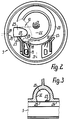
- the sprinkler 1 designed as a sector sprinkler has a sprinkler head 2 shown in FIG. 1, which or its sprinkler nozzle passes through rotating ranges in the controlled forward and return, the rotating ranges being infinitely adjustable between approximately 20 ° and 360 °.
- a fluid drive 3 is provided in the base body 4 of the sprinkler head 2, which is arranged in a drive housing 6 separate from the nozzle head 5, wherein the nozzle head 5 and the drive housing 6 form the base body 4 of the sprinkler head 2.
- the drive housing 6 consists of two axially assembled housing parts 7, 8, and on a housing part 8, the housing-shaped nozzle head 5 with a cap or jacket section is placed axially so that its outer circumference forms an approximately continuous continuation of the outer circumferences of the housing parts 7, 8.
- a reversing control 9 is provided, which switches the direction of rotation by mechanical stop as a function of the path or at the end of a rotational path.
- the base body 4 and the housings 5, 6, together with the drive 3 perform the rotational movement with respect to a shaft which connects to the lower end of the housing part 7 with approximately its outer width and which has a running ring for the engagement of an output rotor of the drive 3 .
- a control device 10 is provided with a plurality of control elements 11, 13 to 20, 23 to 30 and 32 to 36, which form either fixed or moving control elements during operation.
- the water inlet 12 is located at the lower end of the base body 4 or can be formed by a connecting piece on a base, which rotatably receives the sprinkler head 2 and is possibly formed by the shaft in which the sprinkler head 2 is approximately flush with its upper side finally to sink into a non-operational situation or can be extended again by means of water pressure transversely to the axis of the outlet 11.
- the housing parts of the base body 4 form a fluid guide 13 formed by numerous sections or channel sections or chambers, via which the drive 3 is also operated.
- a fluid guide 13 formed by numerous sections or channel sections or chambers, via which the drive 3 is also operated.
- An upper end wall of the control chamber 14 formed by the housing part 8 is penetrated by two upright channel sections 15, 16 which protrude on both sides of this end wall in the manner of pipe sockets, so that their lower ends are connected to the control chamber 14.
- the two channel sections 15, 16 each open into this control chamber 17 with a longitudinally slit-shaped fluid nozzle 18, 19, the discharge direction of the fluid nozzles 18, 19 being directed away from one another at an acute angle of approximately 40 ° against the inner circumference of the control chamber 17.
- the central axes of the fluid nozzles 18, 19 are on the inner circumference of the control chamber 17 with respect to its central axis at an arc distance of 90 ° or more apart.
- a control rotor 20 is also rotatably mounted about an eccentric rotor axis 21 parallel to the central axis 22 of the control chamber 17 or the base body 4, the outer circumference of which lies directly adjacent to the fluid nozzles 18, 19, so that it covers them approximately.
- the relatively wide bowl casing of the approximately bowl-shaped control rotor 20 is formed by approximately radially oriented guide vanes or vane webs which follow one another at intervals, between which the water emerging from the fluid nozzles 18, 19 can enter directly.
- the gaps are closed by a jacket, which is also closed on its bottom, which is closer to the housing part 7.
- the rotor axis 21 on the one hand and the fluid nozzles 18, 19 on the other hand are provided at a distance on both sides of that axial plane of the control chamber 17 which is perpendicular to the common axial plane of the control chamber 17 and the control rotor 20 lying between the fluid nozzles 18.
- the outer circumference of the control rotor 20, which is considerably smaller than the inner circumference of the control chamber 17, extends at one point to close to this inner circumference.
- an inlet 25 is provided in the circumferential direction around the axes 21, 22, directly adjacent to the fluid nozzle 18 or the associated guide surface 23, which extends transversely to the central axis 22 by approximately half the extent has in the circumferential direction about the central axis 22.
- the inlet 25 forms the rear end in the direction of flow of an end channel 26 leading directly to the outlet 11 of the nozzle head 5 and lies in an acute-angled plane of about 30 to 45 ° to the central axis of this end channel 26, so that the inner circumference of the end channel 26 is immediately at a sharp angle to the
- the central axis 22 adjoins the narrower end of the inlet 25, while the inner circumference of the end channel 26 adjoins the opposite end of the inlet 25 approximately at right angles to its plane.
- the end channel 26 is wider or wider than the inlet 25, but it adjoins the side of the inlet 25 remote from the fluid nozzle 18 approximately tangentially, so that it is on the side closer to the fluid nozzle 18 in protrudes radially beyond the inlet 25.
- the end channel 26 is in this area separated from the control chamber 17 by a thin control web 27 which forms the associated, approximately rectilinear and longitudinal boundary 27 of the inlet 25 directed away from the fluid nozzle 18 and up to which the associated guide surface 23 extends approximately.
- the lower outer surface of the control web 27 lies approximately in the plane of the inside of the end wall 24, which also has closure members with which the upper ends of the channel sections 15, 16 are closed in such a way that only the fluid nozzles 18, 19 leading away from their peripheries are open.
- the upper end face of the control rotor 20 extends almost to the end wall 24 with a small gap distance.
- the channel lies approximately diametrically to the axis 22, so that the outlet 11 and the inlet 25 are provided axially offset from one another on opposite sides of the axis 22.
- the outlet 11 is formed by a nozzle 28 or an easily replaceable nozzle insert, which protrudes closely into the end channel 26 with a sleeve and forms the nozzle inlet 29 therein.
- the distance between the nozzle inlet 29 and the inlet 25 or control member 27 lying at an acute angle is less than three times or twice the inner width of the end channel 26, compared to which the inner width of the inlet 29 is only slightly reduced.
- An inlet channel extends from the nozzle inlet 29 with essentially the same width in the direction of flow to a substantially narrower, shorter and cylindrical nozzle channel 30, in which the inlet channel merges over a frustoconical section and the length of which is at most as large as its width or smaller.
- the end channel 30 can be funnel-shaped at the outer end and over a smaller part of its length, these Extension on a free end face forms the sprinkler outlet 11, which is surrounded by a relatively narrow, annular tear-off edge for the jet.
- the outlet 11 can be surrounded in a radial distance and in a ring by a further jacket projecting further forward, the free end of which is still touched on the inner circumference by the water jet emerging from the outlet 11, provided that this is fanned out at approximately the cone angle of the outlet 11 and thereby as Spray jet is discharged.
- longitudinal ribs distributed over the circumference can be provided in the inlet channel, which still leave a central area free, which corresponds at least to the width of the end channel 30 or is larger in comparison.
- the outlet 11, the end channel 26, the nozzle inlet 29 and the nozzle channel 30 are expediently coaxial to one another in the axis 31 of the nozzle insert 28, which forms only a single channel section for the fluid.
- the distance between input 29 and output 11 is approximately in the order of the remaining length of channel 26.
- the central or axial plane of the axes 21, 22 lying between the fluid nozzles 18, 19 is designated by 37, while the axial plane of the central axis 22 at right angles thereto is designated by 38 and extends approximately through the middle of the width of the inlet 25.
- An axial plane 39 of the central axis 22, which is approximately parallel to the boundary edge of the control web 27, is offset relative to the axial plane 38 to the fluid nozzle 18 and at an angle of a few degrees with respect to the axial plane 38.
- the distance between the fluid nozzle 18 and the inlet 25 is approximately in the order of its width or is smaller in comparison, this fluid nozzle 18 causing a direction of rotation of the control rotor 20, which is directed from the fluid nozzle 18 directly to the inlet 25 by the shortest route.
- the other fluid nozzle 19 causes an opposite direction of rotation of the control rotor 20, so that the water emerging from it must be carried over most of the circumference of the rotor 20 until it reaches the limit of the inlet 25 opposite the control member 27.
- the control member 27 covers part of the passage cross section of the channel 26 with respect to the chamber 17, and the inlet 25 is eccentric to the axes 21, 22 laterally adjacent to the central axis 37.
- the end channel 26 is cylindrical over most of its length, but due to its inclined position in the area of the inlet 25, cross sections lying at right angles to the latter, which deviate from the circular shape, are approximately oval, but the oval apex associated with the inlet 25 in FIG Level of the inside of the end wall 24 is cut off at about a third of the oval height.
- the inner circumference or the channel wall 32 of the end channel 26 borders on the side opposite the control member 27 as the associated boundary of the inlet 25 in cross section at an acute angle to the plane of the inlet 25 such that the channel wall 32 extends from this region in a concavely curved manner and the limit of the inlet 25 opposite the control member 27 is limited in cross section by flanks lying at an acute angle to one another.
- the channel wall 32 also extends from the associated inside of the control web 27.
- the control rotor 20 reaches it in the shortest possible way along the underside of the control member 27 into the area of the inlet 25, where it flows against the limitation of the inlet 25 opposite the control member 27. is transferred along the channel wall 32 into a roll flow continuing in the end channel 26 and on the inside of the control member 27 is deflected so that it cannot get back into the control chamber 17 through the inlet 25, but in turn flows towards the opposite region of the channel wall 32.
- the water emerges from the fluid nozzle 19 when the fluid nozzle 18 is blocked, it first drives the rotor 20, but then comes free from the guide surface 23, so that it can flow freely into the control chamber 17 and its flow can be calmed there. The water then flows against the area of the inner circumference of the fully filled control chamber 17 which is in the extension of the guide surface 23 and enters the inlet 25 calmly, so that it reaches the nozzle inlet 29 with a substantially linear flow behavior and as a puncture jet with one of the widths of the nozzle channel 30 corresponding diameter emerges.
- the roll flow In the case of the generation of the roll flow, on the other hand, it enters the nozzle inlet 29 and continues into the nozzle channel 30, so that the water is fanned out as it enters the enlarged outlet 11 and is discharged as an acute or obtuse conical spray steel.
- the water When operating with the fluid nozzle 19, the water is also conveyed by the rotor 20 over the larger circumferential path to the inlet 25, because the rotor 20 sets the water in the control chamber 17 in a corresponding rotational movement.
- the control member 27 With the associated flow against the inlet 25, the control member 27 is essentially ineffective or its effect is such that it causes no or at most only a very reduced vortex or roller flow.
- counter-rotating roller flows can also be generated in the end channel 26, one of which, for. B. is much weaker than the other and therefore on the linearization means in the inlet channel of the nozzle 28th again calming sufficiently to form the piercing jet corresponding to its diameter in the smooth-walled nozzle channel 30.
- this remains in the core of the inlet channel, the core flow in the region of the inlet of the nozzle channel 30 being compressed with the jacket flow flowing along the longitudinal webs and thereby being further swirled.
- a valve 33 is provided, which is expediently located within the control chamber 14 and whose two-armed rocker-shaped closing part 34 acts directly on the inlets of the channel sections 15, 16 in that it seals against one of the two end faces of the tubular Extensions are present and the other inlet to the control chamber 14 is open.
- the closing part 34 is actuated by a valve control 35, which has an actuating member 36 which projects freely downward through the lower end wall of the control chamber 14 and in the form of a rod. This lies laterally adjacent to the central axis 22 on the side facing away from the axis 21, so that it executes an arc movement corresponding to the angle of rotation with the base body 4 about the axis 22.
- the actuator 36 moves between manually adjustable, not shown stops, which are mounted on the base. If the actuator 36 hits a stop, it is pivoted about an axis intersecting the axis 22 and its longitudinal axis approximately at right angles by a few angular degrees and takes over the closing member from the previous control position into the other control position via a control rocker located within the control chamber 14 an intermediate spring so that the closing member 34 is resiliently pressed against the associated valve seat and thereby the fluid enters the control chamber 17 from a fluid nozzle 18 or 19 is switched to the other.
- the stops on the one hand, the angular position and, on the other hand, the angular size of the irrigation sector can be set as desired.
- control device 10 Essentially all parts of the control device 10 are also suitable for causing the rotary movement of the sprinkler head 2 to be driven, so that apart from a multi-stage gearbox, no further components are required for this.
- the control rotor 20 serves as a drive rotor for this transmission, which has two transmission shafts 41 which are offset axially parallel to the rotor axis 21 and which have alternately intermeshing gear wheels and in a dry transmission chamber separate from the fluid guide 13 on which the control chamber 14 or the fluid nozzles 18, 19 opposite side of the axes 21, 22 is located.
- the valve 33 also serves as a reversing valve of the reversing control 9, the direction of rotation of the control rotor 20, the gearbox and the driven pinion 42 being reversed by switching from one fluid nozzle 18, 19 to the other, so that the sprinkler head 5 changes its direction of rotation changes.
Landscapes
- Agricultural Chemicals And Associated Chemicals (AREA)
- Nozzles (AREA)
- Catching Or Destruction (AREA)
- Spray Control Apparatus (AREA)
Applications Claiming Priority (2)
| Application Number | Priority Date | Filing Date | Title |
|---|---|---|---|
| DE4329616 | 1993-09-02 | ||
| DE4329616A DE4329616A1 (de) | 1993-09-02 | 1993-09-02 | Regner, insbesondere zur Vegetations-Bewässerung |
Publications (2)
| Publication Number | Publication Date |
|---|---|
| EP0641603A1 true EP0641603A1 (fr) | 1995-03-08 |
| EP0641603B1 EP0641603B1 (fr) | 2001-11-07 |
Family
ID=6496653
Family Applications (1)
| Application Number | Title | Priority Date | Filing Date |
|---|---|---|---|
| EP94113286A Expired - Lifetime EP0641603B1 (fr) | 1993-09-02 | 1994-08-25 | Arroseur, notamment pour l'irrigation de la végétation |
Country Status (7)
| Country | Link |
|---|---|
| US (1) | US5611488A (fr) |
| EP (1) | EP0641603B1 (fr) |
| AT (1) | ATE208236T1 (fr) |
| AU (1) | AU686640B2 (fr) |
| DE (2) | DE4329616A1 (fr) |
| ES (1) | ES2167342T3 (fr) |
| ZA (1) | ZA946152B (fr) |
Families Citing this family (38)
| Publication number | Priority date | Publication date | Assignee | Title |
|---|---|---|---|---|
| ITRE20010016A1 (it) * | 2001-02-28 | 2002-08-28 | Gf Srl | Irrigatore a getto modulato |
| DE10142144A1 (de) * | 2001-08-29 | 2003-03-20 | Gardena Kress & Kastner Gmbh | Beregnungsvorrichtung |
| WO2003020431A1 (fr) | 2001-08-29 | 2003-03-13 | Gardena Manufacturing Gmbh | Dispositif d'arrosage |
| DE10142143A1 (de) * | 2001-08-29 | 2003-03-27 | Gardena Kress & Kastner Gmbh | Antriebsvorrichtung für eine Beregnungsvorrichtung |
| DE10300206B3 (de) * | 2003-01-08 | 2004-03-04 | Berthold Pelikan | Sprinkler zum Berieseln von Rasen- und Agrarflächen |
| US7090146B1 (en) | 2004-03-23 | 2006-08-15 | Orbit Irrigation Products, Inc. | Above-ground adjustable spray pattern sprinkler |
| TWI273883B (en) * | 2005-11-30 | 2007-02-21 | Yuan Mei Corp | Automatic switching device for water entry of sprinkler |
| US7255291B1 (en) * | 2006-10-06 | 2007-08-14 | Yuan Mei Corp. | Multifunctional sprinkler structure |
| GB2442699B (en) * | 2006-10-09 | 2009-12-16 | Yuan Mei Corp | Multifunctional sprinkler structure |
| DE102006048211A1 (de) * | 2006-10-11 | 2008-04-30 | Yuan Mei Corp. | Multifunktioneller Sprengeraufbau |
| FR2907349B1 (fr) * | 2006-10-24 | 2009-01-23 | Yuan Mei Corp | Structure d'arroseur a fonctions multiples |
| US8651400B2 (en) * | 2007-01-12 | 2014-02-18 | Rain Bird Corporation | Variable arc nozzle |
| US8074897B2 (en) | 2008-10-09 | 2011-12-13 | Rain Bird Corporation | Sprinkler with variable arc and flow rate |
| US8272583B2 (en) * | 2009-05-29 | 2012-09-25 | Rain Bird Corporation | Sprinkler with variable arc and flow rate and method |
| US8925837B2 (en) | 2009-05-29 | 2015-01-06 | Rain Bird Corporation | Sprinkler with variable arc and flow rate and method |
| US8695900B2 (en) | 2009-05-29 | 2014-04-15 | Rain Bird Corporation | Sprinkler with variable arc and flow rate and method |
| WO2011002928A1 (fr) * | 2009-07-01 | 2011-01-06 | Rain Bird Corporation | Pulvérisateur d'irrigation rotatif avec système d'entraînement monté sur une tourelle |
| US9427751B2 (en) | 2010-04-09 | 2016-08-30 | Rain Bird Corporation | Irrigation sprinkler nozzle having deflector with micro-ramps |
| US9504209B2 (en) | 2010-04-09 | 2016-11-29 | Rain Bird Corporation | Irrigation sprinkler nozzle |
| TWM400889U (en) | 2010-10-22 | 2011-04-01 | Kwan-Ten Enterprise Co Ltd | Gear-type water spraying device |
| US9120111B2 (en) | 2012-02-24 | 2015-09-01 | Rain Bird Corporation | Arc adjustable rotary sprinkler having full-circle operation and automatic matched precipitation |
| US9079202B2 (en) | 2012-06-13 | 2015-07-14 | Rain Bird Corporation | Rotary variable arc nozzle |
| US9174227B2 (en) | 2012-06-14 | 2015-11-03 | Rain Bird Corporation | Irrigation sprinkler nozzle |
| ES2661502T3 (es) * | 2012-06-28 | 2018-04-02 | Netafim Ltd. | Un aspersor giratorio |
| US9156043B2 (en) | 2012-07-13 | 2015-10-13 | Rain Bird Corporation | Arc adjustable rotary sprinkler with automatic matched precipitation |
| US9295998B2 (en) | 2012-07-27 | 2016-03-29 | Rain Bird Corporation | Rotary nozzle |
| US9327297B2 (en) | 2012-07-27 | 2016-05-03 | Rain Bird Corporation | Rotary nozzle |
| US9314952B2 (en) | 2013-03-14 | 2016-04-19 | Rain Bird Corporation | Irrigation spray nozzle and mold assembly and method of forming nozzle |
| CN103480517B (zh) * | 2013-09-22 | 2016-07-20 | 江苏大学 | 一种椭圆形喷洒域喷头压力调节装置 |
| TWI533934B (zh) * | 2014-07-01 | 2016-05-21 | Qing-Nan Chen | Air guide rotary spray device and air guide rotary sprayer |
| US10322421B2 (en) | 2015-04-14 | 2019-06-18 | Yuan-Mei Corp. | Sprinkler |
| US9775306B2 (en) | 2015-04-14 | 2017-10-03 | Yuan-Mei Corp. | Above ground sprinkler |
| US10322423B2 (en) | 2016-11-22 | 2019-06-18 | Rain Bird Corporation | Rotary nozzle |
| US11154877B2 (en) | 2017-03-29 | 2021-10-26 | Rain Bird Corporation | Rotary strip nozzles |
| US11059056B2 (en) | 2019-02-28 | 2021-07-13 | Rain Bird Corporation | Rotary strip nozzles and deflectors |
| US11047502B2 (en) * | 2019-03-08 | 2021-06-29 | John S. Heaney | Magnetically coupled actuator and lead screw control for a variable pressure pilot valve |
| US11406999B2 (en) | 2019-05-10 | 2022-08-09 | Rain Bird Corporation | Irrigation nozzle with one or more grit vents |
| US11247219B2 (en) | 2019-11-22 | 2022-02-15 | Rain Bird Corporation | Reduced precipitation rate nozzle |
Citations (4)
| Publication number | Priority date | Publication date | Assignee | Title |
|---|---|---|---|---|
| DE3442496A1 (de) * | 1983-12-02 | 1985-06-13 | Joel Ringwood N.J. Schwartzman | Wasserspruehvorrichtung |
| US4760958A (en) * | 1986-02-10 | 1988-08-02 | Plastro Gvat And Agroteam Consultants Ltd. | Water sprinkler |
| EP0362559A2 (fr) * | 1988-10-06 | 1990-04-11 | GARDENA Kress + Kastner GmbH | Dispositif d'entraînement pour dispositif d'arrosage ou dispositif similaire |
| EP0410198A2 (fr) * | 1989-07-27 | 1991-01-30 | GARDENA Kress + Kastner GmbH | Arroseur escamotable |
Family Cites Families (14)
| Publication number | Priority date | Publication date | Assignee | Title |
|---|---|---|---|---|
| US965941A (en) * | 1909-11-10 | 1910-08-02 | Campbell Printing Press & Mfg | Mechanical movement. |
| DE2412748B2 (de) * | 1974-03-16 | 1978-04-06 | Gardena Kress + Kastner Gmbh, 7900 Ulm | Beregnungsvorrichtung |
| US4417691A (en) * | 1976-11-08 | 1983-11-29 | Anthony Manufacturing Corp. | Turbine drive water sprinkler |
| US4253608A (en) * | 1979-05-21 | 1981-03-03 | The Toro Company | Part-circle sprinkler with reversible stator |
| US4613077A (en) * | 1984-04-09 | 1986-09-23 | Aronson Jeffry D | Programmable sprinkler |
| SU1214230A1 (ru) * | 1984-04-29 | 1986-02-28 | Предприятие П/Я В-8745 | Устройство дл орошени |
| US4867379A (en) * | 1986-06-26 | 1989-09-19 | Hunter Edwin J | Rotary stream sprinkler unit |
| DE3730192A1 (de) * | 1987-01-09 | 1988-07-21 | Heinz Kern | Spritzvorrichtung fuer beregnungsanlagen |
| US4867378A (en) * | 1987-04-13 | 1989-09-19 | Kah Jr Carl L C | Sprinkler device |
| US5213016A (en) * | 1987-04-13 | 1993-05-25 | Kah Jr Carl L C | Sprinkler device |
| US4819875A (en) * | 1987-06-22 | 1989-04-11 | Rain Bird Consumer Products Mfg. Corp. | Contour control device for rotary irrigation sprinklers |
| US4892252A (en) * | 1988-11-03 | 1990-01-09 | L. R. Nelson Corporation | Adjustable part circle sprinkler assembly |
| US4972993A (en) * | 1989-04-10 | 1990-11-27 | Gardenamerica Corporation | Vandal-proof oscillating irrigation sprinkler |
| US5226599A (en) * | 1989-07-27 | 1993-07-13 | Gardena Kress & Kastner Gmbh | Flush sprinkler |
-
1993
- 1993-09-02 DE DE4329616A patent/DE4329616A1/de not_active Withdrawn
-
1994
- 1994-08-16 ZA ZA946152A patent/ZA946152B/xx unknown
- 1994-08-23 AU AU71409/94A patent/AU686640B2/en not_active Ceased
- 1994-08-23 US US08/294,309 patent/US5611488A/en not_active Expired - Fee Related
- 1994-08-25 EP EP94113286A patent/EP0641603B1/fr not_active Expired - Lifetime
- 1994-08-25 DE DE59409937T patent/DE59409937D1/de not_active Expired - Fee Related
- 1994-08-25 ES ES94113286T patent/ES2167342T3/es not_active Expired - Lifetime
- 1994-08-25 AT AT94113286T patent/ATE208236T1/de not_active IP Right Cessation
Patent Citations (4)
| Publication number | Priority date | Publication date | Assignee | Title |
|---|---|---|---|---|
| DE3442496A1 (de) * | 1983-12-02 | 1985-06-13 | Joel Ringwood N.J. Schwartzman | Wasserspruehvorrichtung |
| US4760958A (en) * | 1986-02-10 | 1988-08-02 | Plastro Gvat And Agroteam Consultants Ltd. | Water sprinkler |
| EP0362559A2 (fr) * | 1988-10-06 | 1990-04-11 | GARDENA Kress + Kastner GmbH | Dispositif d'entraînement pour dispositif d'arrosage ou dispositif similaire |
| EP0410198A2 (fr) * | 1989-07-27 | 1991-01-30 | GARDENA Kress + Kastner GmbH | Arroseur escamotable |
Also Published As
| Publication number | Publication date |
|---|---|
| EP0641603B1 (fr) | 2001-11-07 |
| ES2167342T3 (es) | 2002-05-16 |
| DE59409937D1 (de) | 2001-12-13 |
| ZA946152B (en) | 1995-03-22 |
| DE4329616A1 (de) | 1995-03-09 |
| AU686640B2 (en) | 1998-02-12 |
| AU7140994A (en) | 1995-03-16 |
| ATE208236T1 (de) | 2001-11-15 |
| US5611488A (en) | 1997-03-18 |
Similar Documents
| Publication | Publication Date | Title |
|---|---|---|
| EP0641603B1 (fr) | Arroseur, notamment pour l'irrigation de la végétation | |
| EP0826426B1 (fr) | Arroseur | |
| EP0698417B2 (fr) | Arroseur pour la distribution d'un fluide | |
| DE2401127C3 (de) | Fluidischer Oszillator | |
| DE69225409T2 (de) | Düsenanordnung für zerstäuber vom triggertyp | |
| EP0157250B1 (fr) | Appareil de traitement de semences par des liquides | |
| DE2803325A1 (de) | Fluessigkeitsspritzkopf und verfahren zum spritzen eines spezifischen musters | |
| DE69516794T2 (de) | Verbesserungen an Pumpenzerstäubern | |
| DE3036776A1 (en) | Fluidic oscillator with resonant inertance and dynamic compliance circuit | |
| DE2166353A1 (de) | Spruehkopf fuer eine brause oder dgl | |
| DE2609557B2 (de) | Brausekopf | |
| DE2911405A1 (de) | Pulsierende wasserstrahlen erzeugende massagebrause | |
| DD140713A5 (de) | Spritzduese | |
| DE10006864B4 (de) | Reinigungsdüse | |
| DE1782094B1 (de) | Rasensprenger | |
| DE3511314A1 (de) | Brausekopf zum erzeugen eines pulsierenden strahls | |
| DE3150879A1 (de) | "fluidventil mit einem gerichteten auslassstrahl einer sich fortwaehrend aendernden richtung" | |
| DE3110029C2 (fr) | ||
| CH637285A5 (en) | Liquid pulse generator, especially for mouth douches | |
| EP0410198B1 (fr) | Arroseur escamotable | |
| DE2757522B1 (de) | Rund- oder Ringstrahlduese zum Erzeugen und Abstrahlen eines Nebels oder Aerosols zur Beschichtung von Gegenstaenden | |
| DE4343009C2 (de) | Einspritzvorrichtung, insbesondere für ein Strahltriebwerk | |
| EP1084755B1 (fr) | Dispositif de distribution de fluide, en particulier un dispositif portable avec une buse de pulvérisation et une pomme d'arrosoir | |
| DE3208442A1 (de) | Verteilerkopf fuer eine beregnungseinrichtung | |
| DE2017600A1 (de) | Sprühkopf, insbesondere fur eine Dusche |
Legal Events
| Date | Code | Title | Description |
|---|---|---|---|
| PUAI | Public reference made under article 153(3) epc to a published international application that has entered the european phase |
Free format text: ORIGINAL CODE: 0009012 |
|
| AK | Designated contracting states |
Kind code of ref document: A1 Designated state(s): AT DE ES FR GB IT NL SE |
|
| 17P | Request for examination filed |
Effective date: 19950426 |
|
| 17Q | First examination report despatched |
Effective date: 19970226 |
|
| GRAG | Despatch of communication of intention to grant |
Free format text: ORIGINAL CODE: EPIDOS AGRA |
|
| GRAG | Despatch of communication of intention to grant |
Free format text: ORIGINAL CODE: EPIDOS AGRA |
|
| GRAH | Despatch of communication of intention to grant a patent |
Free format text: ORIGINAL CODE: EPIDOS IGRA |
|
| GRAH | Despatch of communication of intention to grant a patent |
Free format text: ORIGINAL CODE: EPIDOS IGRA |
|
| GRAA | (expected) grant |
Free format text: ORIGINAL CODE: 0009210 |
|
| AK | Designated contracting states |
Kind code of ref document: B1 Designated state(s): AT DE ES FR GB IT NL SE |
|
| REF | Corresponds to: |
Ref document number: 208236 Country of ref document: AT Date of ref document: 20011115 Kind code of ref document: T |
|
| GBT | Gb: translation of ep patent filed (gb section 77(6)(a)/1977) |
Effective date: 20011107 |
|
| REF | Corresponds to: |
Ref document number: 59409937 Country of ref document: DE Date of ref document: 20011213 |
|
| REG | Reference to a national code |
Ref country code: GB Ref legal event code: IF02 |
|
| REG | Reference to a national code |
Ref country code: ES Ref legal event code: FG2A Ref document number: 2167342 Country of ref document: ES Kind code of ref document: T3 |
|
| PGFP | Annual fee paid to national office [announced via postgrant information from national office to epo] |
Ref country code: SE Payment date: 20020823 Year of fee payment: 9 |
|
| PLBE | No opposition filed within time limit |
Free format text: ORIGINAL CODE: 0009261 |
|
| STAA | Information on the status of an ep patent application or granted ep patent |
Free format text: STATUS: NO OPPOSITION FILED WITHIN TIME LIMIT |
|
| 26N | No opposition filed | ||
| PGFP | Annual fee paid to national office [announced via postgrant information from national office to epo] |
Ref country code: GB Payment date: 20030808 Year of fee payment: 10 |
|
| PGFP | Annual fee paid to national office [announced via postgrant information from national office to epo] |
Ref country code: NL Payment date: 20030818 Year of fee payment: 10 |
|
| PGFP | Annual fee paid to national office [announced via postgrant information from national office to epo] |
Ref country code: ES Payment date: 20030821 Year of fee payment: 10 |
|
| PGFP | Annual fee paid to national office [announced via postgrant information from national office to epo] |
Ref country code: AT Payment date: 20030822 Year of fee payment: 10 |
|
| PG25 | Lapsed in a contracting state [announced via postgrant information from national office to epo] |
Ref country code: SE Free format text: LAPSE BECAUSE OF NON-PAYMENT OF DUE FEES Effective date: 20030826 |
|
| EUG | Se: european patent has lapsed | ||
| PG25 | Lapsed in a contracting state [announced via postgrant information from national office to epo] |
Ref country code: GB Free format text: LAPSE BECAUSE OF NON-PAYMENT OF DUE FEES Effective date: 20040825 Ref country code: AT Free format text: LAPSE BECAUSE OF NON-PAYMENT OF DUE FEES Effective date: 20040825 |
|
| PG25 | Lapsed in a contracting state [announced via postgrant information from national office to epo] |
Ref country code: ES Free format text: LAPSE BECAUSE OF NON-PAYMENT OF DUE FEES Effective date: 20040826 |
|
| PG25 | Lapsed in a contracting state [announced via postgrant information from national office to epo] |
Ref country code: NL Free format text: LAPSE BECAUSE OF NON-PAYMENT OF DUE FEES Effective date: 20050301 |
|
| GBPC | Gb: european patent ceased through non-payment of renewal fee |
Effective date: 20040825 |
|
| NLV4 | Nl: lapsed or anulled due to non-payment of the annual fee |
Effective date: 20050301 |
|
| PG25 | Lapsed in a contracting state [announced via postgrant information from national office to epo] |
Ref country code: IT Free format text: LAPSE BECAUSE OF NON-PAYMENT OF DUE FEES Effective date: 20050825 |
|
| PGFP | Annual fee paid to national office [announced via postgrant information from national office to epo] |
Ref country code: DE Payment date: 20050929 Year of fee payment: 12 |
|
| REG | Reference to a national code |
Ref country code: ES Ref legal event code: FD2A Effective date: 20040826 |
|
| PG25 | Lapsed in a contracting state [announced via postgrant information from national office to epo] |
Ref country code: DE Free format text: LAPSE BECAUSE OF NON-PAYMENT OF DUE FEES Effective date: 20070301 |
|
| PGFP | Annual fee paid to national office [announced via postgrant information from national office to epo] |
Ref country code: FR Payment date: 20120621 Year of fee payment: 19 |
|
| REG | Reference to a national code |
Ref country code: FR Ref legal event code: TP Owner name: HUSQVARNA AB, SE Effective date: 20140407 Ref country code: FR Ref legal event code: CD Owner name: HUSQVARNA AB, SE Effective date: 20140407 |
|
| REG | Reference to a national code |
Ref country code: FR Ref legal event code: ST Effective date: 20140430 |
|
| PG25 | Lapsed in a contracting state [announced via postgrant information from national office to epo] |
Ref country code: FR Free format text: LAPSE BECAUSE OF NON-PAYMENT OF DUE FEES Effective date: 20130902 |