EP0641508B1 - Methode und Vorrichtung zur Verbesserung der Schärfe einer einem kontinuierlichem Zoom unterworfenen Bildfolge - Google Patents
Methode und Vorrichtung zur Verbesserung der Schärfe einer einem kontinuierlichem Zoom unterworfenen Bildfolge Download PDFInfo
- Publication number
- EP0641508B1 EP0641508B1 EP94910913A EP94910913A EP0641508B1 EP 0641508 B1 EP0641508 B1 EP 0641508B1 EP 94910913 A EP94910913 A EP 94910913A EP 94910913 A EP94910913 A EP 94910913A EP 0641508 B1 EP0641508 B1 EP 0641508B1
- Authority
- EP
- European Patent Office
- Prior art keywords
- pass
- signal
- image signal
- image
- bandpass
- Prior art date
- Legal status (The legal status is an assumption and is not a legal conclusion. Google has not performed a legal analysis and makes no representation as to the accuracy of the status listed.)
- Expired - Lifetime
Links
Images


Classifications
-
- G—PHYSICS
- G06—COMPUTING; CALCULATING OR COUNTING
- G06T—IMAGE DATA PROCESSING OR GENERATION, IN GENERAL
- G06T3/00—Geometric image transformation in the plane of the image
- G06T3/40—Scaling the whole image or part thereof
- G06T3/4023—Decimation- or insertion-based scaling, e.g. pixel or line decimation
-
- H—ELECTRICITY
- H04—ELECTRIC COMMUNICATION TECHNIQUE
- H04N—PICTORIAL COMMUNICATION, e.g. TELEVISION
- H04N5/00—Details of television systems
- H04N5/14—Picture signal circuitry for video frequency region
- H04N5/20—Circuitry for controlling amplitude response
- H04N5/205—Circuitry for controlling amplitude response for correcting amplitude versus frequency characteristic
- H04N5/208—Circuitry for controlling amplitude response for correcting amplitude versus frequency characteristic for compensating for attenuation of high frequency components, e.g. crispening, aperture distortion correction
-
- H—ELECTRICITY
- H04—ELECTRIC COMMUNICATION TECHNIQUE
- H04N—PICTORIAL COMMUNICATION, e.g. TELEVISION
- H04N5/00—Details of television systems
- H04N5/222—Studio circuitry; Studio devices; Studio equipment
- H04N5/253—Picture signal generating by scanning motion picture films or slide opaques, e.g. for telecine
-
- H—ELECTRICITY
- H04—ELECTRIC COMMUNICATION TECHNIQUE
- H04N—PICTORIAL COMMUNICATION, e.g. TELEVISION
- H04N5/00—Details of television systems
- H04N5/222—Studio circuitry; Studio devices; Studio equipment
- H04N5/262—Studio circuits, e.g. for mixing, switching-over, change of character of image, other special effects ; Cameras specially adapted for the electronic generation of special effects
- H04N5/2628—Alteration of picture size, shape, position or orientation, e.g. zooming, rotation, rolling, perspective, translation
Definitions
- This invention relates to the field of image signal processing, especially for the purpose of enhancing image features.
- the invention has particular relevance to an electronic imaging system in which the input images are either stationary images or time-varying sequences of images, and in which the output images are subject to a static or dynamic digital zoom.
- the zooming process which may be implemented in a spatial interpolator, such as described in EP-A-0 579 795, may be required for spatial standards conversion, or for image magnification within a given spatial standard.
- an image can be characterized by a two-dimensional parameter known as spatial frequency.
- spatial frequency a sampling frequency (f s ) that is equal to at least twice the bandwidth of the signal.
- the actual bandwidth is ordinarily established by prefiltering the analog signal before it is sampled, so that the band edge of the signal does not exceed the upper frequency limit, which is called the Nyquist frequency, required for sampling.
- Such filters are typically one-dimensional or two-dimensional Finite Impulse Response (FIR) bandpass filters that are programmed in a variety of conventional ways to multiply a sequence of input image samples by a set of coefficients, and to provide the sum thereof as the output of the filter.
- FIR Finite Impulse Response
- the coefficients, which provide a bandpass characteristic are generated in a conventional manner, such as an optimized frequency sampling design technique found in Theory and Application of Digital Processing , by L.R. Rabiner and B. Gold, Prentice-Hall: 1975, pp. 105-123.
- Enhancement is most commonly performed on an image signal after any spatial interpolation, or zooming, is done that might affect the bandwidth of the system, and after the system is accordingly band-limited to prevent aliasing, or otherwise reconverted to the original band of frequencies present before zooming.
- This allows one set of filters to be designed for the various spatial frequencies that are to be enhanced.
- it is generally most beneficial to do enhancement on luminance information; likewise it is most effective to do spatial interpolation on full band color signals, rather than separately on the luminance and color/chroma information in the signal.
- the Gabor filter can be viewed as a sine wave multiplied by a Gaussian window in the spatial domain. The width of the filter is determined by the window, and the peak frequency by the sine waves. In order to define the peak frequency of a Gabor filter, it is necessary for the Gaussian window to envelope a significant number of sine wave cycles at the required frequency.
- EP-A-0 517 474 relates to aperture correction for video cameras, and discloses apparatus comprising a zooming unit having a zoom lens, an image capture device that receives the optical image from the zooming unit and generates a video signal, a circuit for detecting the position of the zoom lens, a circuit for generating a detail signal representative of high frequency information contained in the video signal, and a circuit for controlling the boost frequency of the detail signal in accordance with the output of the position detecting circuit.
- GB-A-2 237 161 relates to a circuit for correcting horizontal edges in a digital image processing, for example video, system.
- the circuit includes three bandpass filters for filtering an input luminance signal to obtain therefrom low, medium and high frequency components respectively, means for controlling respectively the gains of the three filtered signals on the basis of respective control signals; and means for mixing the input luminance signal with all the filtered signals.
- This invention overcomes the disadvantages of the prior art with a small set of fixed bandpass filters with appropriate conventional characteristics (that is, an appropriate bandwidth and stop-band performance, using a number of spatial taps which is practically realizable), which are stored within the imaging system.
- the bandpass filter required for enhancement at any degree of zoom may then be generated by means of an appropriate combination of the stored filters.
- the invention provides that the pass-band of the bandpass enhancement filter tracks changes in spatial frequency due to the zooming process.
- apparatus for enhancing the sharpness of an image signal subject to a zooming process that changes the spatial frequency of the image signal, said apparatus comprising:
- the apparatus is applicable to filtering a digital image signal.
- the primary pass-band is derived from a predetermined combination of a plurality of secondary bandpass filter sections, each responsive to a gain adjustment.
- the control signal reflects the zoom ratio and is used in the adjustment of the gain applied to the filter sections to thereby arrive at the predetermined combination.
- the main advantage of the invention is that the band-edge of the enhancement process is continuously positioned at the proper upper band-edge location after the interpolation section repositions the frequency response of the zoomed signal to account for aliasing. In this way the effect of enhancement is maintained throughout the zoom range, which provides a more effective utilization of the zoom feature.
- the '932 patent shows the generation of a high definition television signal from the combination of a high definition detail component (a luminance signal) and a plurality of lower definition color components. Enhancement, as disclosed in the present invention, is performed on a high definition component before it is combined with any lower definition color components, and before performing spatial interpolation.
- the spatial interpolation may take several forms, including the example described herein in relation to Figures 5 and 6, or in an improved form expressed in the aforementioned EP-A-0 579 795.
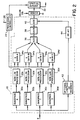
- FIG. 1 shows a digital image processing system incorporating a tracked enhancement section 10 in accordance with the invention.
- the processing system is designed for use in a telecine film scanner of the type described in U.S. Patent 5,045,932, which includes a film scanner 12 for producing a high definition luminance (detail) signal 12a and a plurality 12b of low definition color signals.
- the film scanner 12 develops image pixel data corresponding to image pixel areas on a motion picture film.
- the image pixel data is processed as the luminance signal 12a and color signals 12b through an analog-to-digital converter 14 and an input image store 16.
- the color signals 12b are then processed in a color processing channel 13, which, as described in the aforementioned U.S. Patent No.
- the luminance signal 12a is processed through a luminance processing channel 18, and the tracked enhancement section 10.
- the enhanced luminance signal 12a and the color signals 12b are then combined in an adder 19 and processed through a spatial interpolator 20 and an output image store 22.
- a controller 24 provides system timing for pipelined operation according to the scanning speed of the film scanner 12 and the television standard in use. Film pixel data from the film scanner 12 is converted to digital pixel data by the A/D converter 14 and applied to the input image store 14 at a real-time, synchronous rate determined by the controller 24.
- a control signal is input to the controller 24 from a zoom ratio generator 26.
- the degree of zoom may be operator-determined, illustratively from a knob 28 connected to the zoom ratio generator 24.
- a new output image is derived from the input data.
- the new output image data is interpolated from the input data in the spatial interpolator 20.
- the channel data rate is maintained at the level required for pipelined operation by controlling the readout of the input image store 16. Over the active area of the zooming, lines and pixels are repeated, or deleted, as necessary for optimum interpolation of the new output data.
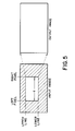
- Line A shows original input pixels from the portion a (see Fig. 5) of the full input image produced according to the system timing illustrated in Line C.
- Line B illustrates the output pixels needed (for a 2:1 zoom) from the active portion a to produce a full-sized output image (see Fig. 5).
- Lines A and B represent the spatial relationship between the original input and "zoomed-in" pixels, respectively. Zooming is obtained, in the luminance channel, by writing into the input store 16 at the synchronous rate represented by the Line C timing, and then controlling readout of the input store so as to repeat samples in its output.
- FIG. 2 A block diagram of a preferred implementation of the tracked enhancement filter 10 is shown in Figure 2.
- the signal from the luminance processing channel 18 is applied in parallel to a bank of bandpass filter sections 30a, 30b, 30c, 30d...
- Each filter section contains the digital filter coefficients for an appropriate bandpass filter characteristic, e.g., bandpass filter section 30a contains filter coefficients A, bandpass filter section 30b contains filter coefficients B, and so on.
- a non-linear process may be applied to the outputs of each of the filter sections 30a, 30b, 30c, 30d in respective nonlinear processors 32a, 32b, 32c, 32d, e.g., for the purpose of noise suppression.
- the thus-adjusted bandpass signals are then modified in a set of gain multipliers 34a, 34b, 34c, 32d by respective gain factors that are a predetermined function of the amount of zoom specified by the zoom ratio generator 26.
- the bandpass signals are then combined in an adder 36 to obtain the primary pass-band signal, and an overall gain factor can be applied in the gain stage 38 to tailor the overall level of sharpness enhancement in the overall pass-band.
- the enhanced bandpass signal could be combined with the full band signal in an adder 40, the full band signal being input to the adder 40 either directly to the adder 40 or through an optional low-pass or high-pass filter 42. (A delay to compensate for the bandpass filtering is also inserted by a delay element 44).
- the preferred embodiment of the invention relates to the implementation of tracked enhancement preceding spatial interpolation in an HDTV telecine application.
- three two-dimensional bandpass filters are stored within the bandpass filter sections 30a, 30b, 30c, each of an 'X' shaped configuration, such that the frequency response of the filter is maximized in the horizontal and vertical orientations, and minimized diagonally.
- the three filters are generated using a difference-of-Gaussian approach, and hence, when added together in varying proportions produce a single filter with a smooth frequency response.
- the filters comprise coefficients which are powers of two and therefore may be readily implemented using digital techniques.
- the filter coefficients are as follows: Within the telecine application, spatial interpolation may be required with a minimum zoom ratio of approximately 0.375 (corresponding to HDTV to 525 line down-conversion) and a maximum zoom ratio greater than 1.0. At any particular zoom ratio, only two of the three filters are employed; filters 'B' and 'C' for zoom ratios less than 0.5, and filters 'A' and 'B' for zoom ratios greater than or equal to 0.5 (i.e., a gain of zero could be applied to the filter section not in use, or the filter may be re-configured to be either the 'A' or 'C' filter, as required).
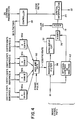
- FIG. 3 A hardware implementation of the invention is illustrated in Figure 3, comprising a block 50 of line delays, detail extract (bandpass) filters 52, 54, a complementary average generator 56, look-up tables (LUTs) 58, 60, and output adders 64 and 66.
- the complementary average generator 56 provides a smoothed signal over several lines that is complementary to the color signal.
- the delay block 50 delays the input data by up to six lines, E0 to E6, where E0 is the undelayed data and E6 is the data delayed by six lines.
- E3 delayed (E3D) is thus the delayed center line.
- a complementary detail signal is generated in the second adder 66, by subtraction of the complementary average signal from the delayed center line (E3D) signal.
- the detail extract filters 52, 54 use the appropriately delayed data as shown in Figure 3.
- the filter 52 is switched between the 3x3 filtered output (using filter coefficients A) and the 7x7 filtered output (using filter coefficients C).
- the filter 54 generates only the 5x5 output (using filter coefficients B).
- the two detail output signals are applied to the two LUTs 58, 60 before being summed by the adder 64.
- the proportions (gains) of the two detail signals may be set either by using the LUTs 58, 60, or by scaling the inputs to the adder 64, or by a combination of the two methods. It is also possible to rescale the output of the detail filters 52, 54.
- the proportions are programmed by controller 24 with the appropriate gain characteristic as determined for each zoom ratio according to the appropriate gain relationships (4), (5), (6), or (7).
- two LUTs may be used in each bandpass detail signal path so that one may be loaded while the other is read; in this way the zoom ratio may be varied on a frame-to-frame basis with no disruption of the output data.
- the signals from the output adder 64 may be set by a "boost" control input 68 to give the desired overall level of enhancement.
- the combined detail signal is added in the output adder 66 to the complementary detail signal to provide a complete detail signal with tracked enhancement for input to the adder 19 ( Figure 1) prior to the spatial interpolator 20. While a non-linear noise suppression process is not shown in Figure 3, it may be obtained by addition of conventional non-linear elements in each of the bandpass signal channels.
- FIG. 7 shows a diagram of the basic elements of a unit processor 70 as described in EP-A-0 597 083. Mode lines are used to select an input configuration of pixels, the number of pixels of delay, the data bit shift, and an output rescale coefficient.
- the input select mode line a and the delay mode lines b program the processor to one of three basic filter configurations:
- the processing unit 70 of Figure 7 comprises two processing sections 71 and 72.
- processing section 71 a time series of digital signals are input through line A IN to a latch 73, which is clocked (clock not shown) to provide at least a one-clock delay and to set the timing of the input data to a known reference point.
- the output of the latch 73 is routed to a channel selector 74, a delay 75, and an input selector 76.
- the delay 75 may be programmed by the delay mode line b to a variable number of clocks of delay corresponding to discrete pixel delays of between 0 and 8 elements.
- the channel selector 74 may be programmed by a switch mode line d to set all zeros at its output or to connect its input straight through to its output without change.
- the outputs of the channel selector 74 and the delay 75 are applied to the two inputs of an adder 77 and the output of the adder 77 is then bit-shifted in a scaler 78.
- the scaler 78 applies a conventional bit-shifting arithmetic operation, in which the number of bits of right shift are set by the scale mode line ("Z" being a zero output condition). Bits of right-shift correspond to "powers of two" division for positive filter coefficients and bits of right shift followed by complementing correspond to "powers of two" division for negative filter coefficients (i.e, shifts of 0, 1, 2, or 3 provide division by 1, 2, 4, or 8, or, with complementing, division by -1, -2, -4, or -8).
- the input selector 76 is programmed by the input select mode line a to select either data from the latch 73 or data input through the line B IN .
- data from the latch 73 is a continuation of the same dimension data, while data input through the line B IN is delayed sufficiently with respect to the signals input to the latch 10 as to represent a second dimension (line) of data. If the input selector 76 is programmed to route the data from the latch 73 through to a latch 79 in the processing section 72, then it can be seen that the data at the output of the latch 79 is one clock period (or, for image data, one pixel) later than the data at the output of the latch 73.
- the output of the latch 79 in processing section 72 is routed through channel selector 80 and a delay 81 to an adder 82.
- the adder output is then scaled by a scaler 83.
- the amount of delay for one input to the adder 82 is programmed by the delay mode line b to the delay 81.
- the other input to the adder 82 is programmed by the switch mode line d to the channel selector 80 to be either all zeros or to be the input to the selector 80.
- the value of the arithmetic operation performed upon the output of the adder 82 is controlled by the shift input on the scale mode line c to the scaler 83.
- the scaler either shifts up to three bits (or no shift), or has a zero (Z) output.
- the respective outputs of the scalers 78 and 83 are applied to respective latches 84 and 85 to restore the data timing.
- An adder 86 then combines the scaled values from the sections 71 and 72 into a single output sum signal.
- the delay 75 is set to two pixels and the channel selector 74 is set to pass its input through without change.
- the output of the adder 77 then will be the sum of pixel (0) and pixel (-2). If the input selector 76 is set to select data from the latch 73, the channel selector 80 is set to zero output, and the delay 81 is set to zero delay, then the output of the adder 82 will be pixel (-1). This is due to the one pixel delay in the latch 79.
- the outputs of the adders 77 and 82 are then scaled by scalers 78 and 83 and latched in latches 84 and 85 to restore the data timing.
- the scalers 78 and 83 can be set to the zero output condition (Z), or to divide by 1, 2, 4, or 8 by right bit shifting, or to divide by -1, -2, -4, or -8 by right bit shifting and complementing for negative filter coefficients. More specifically, if the scaler 78 is set to "2" then its output will be the addition of pixel (0) and pixel (-2) divided by two. If scaler 83 is set to "1", then its output will be pixel (-1) with no scaling. These scale settings provide (from the adder 86) a low pass output having a weighting function of 0.5, 1.0, 0.5 upon any set of three pixels, that is, the sum of pixel (0) and pixel (-2) divided by two plus pixel (-1). If the scale factor of the scaler 78 were set to -2, then adder 86 would provide a high pass output having a weighting function of -0.5, 1.0, -0.5, and so on.
- One feature of the shift and add processor is the flexibility provided by enabling the selector 76 to select either the output of the latch 73 or the input on the line B IN . If the input selector 76 is set to select the input B IN and the data at B IN is one video line later than that at A IN , a vertical average of the image data will be obtained.
- the line delay will ordinarily be obtained by a one-line delay element, not shown, arranged to precede the B IN input to the input selector 76; a conventional delay line or a memory-based line delay may be used.
- a conventional delay line or a memory-based line delay may be used.
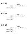
- the output of the adder 86 will be a four-pixel area average of pixels (0) and (-2) from line (0) and pixels (0) and (-2) from line (1) (as shown in Figure 8C).
- Figure 7 also shows a cascaded arrangement of unit processor 70 with one or more additional unit processors 70' for carrying out larger filter implementations, including "X" type filters over larger pixel areas using a combination of external line delays and internal pixel delays.
- the basic functions of the elements of the unit processor 70 are duplicated in the functions of the additional unit processor 70', with the addition of an input selector 87 for selecting either the output of the latch 79 in processor 70 or the input on the line C IN (input selector 88 likewise can optionally select the input on line D IN and input selector 89 can select the input on line E IN ).
- the cascaded filter processor of Figure 7 may be configured to carry out various functions as described in detail in EP-A-0 597 083, including, for example, a nine-pixel average along a line shown in Figure 8D, or a 5x5 "X" type matrix average over a block of pixels as shown in Figure 8E, or a 3x3 "X" type matrix as shown in Figure 8F.
- the technique of enhancement provides a series of digital bandpass filters with peak amplitude at a continuously variable frequency, appropriate for use in a sequence of image signals which is subject to dynamic or static zoom, or on a static image subject to spatial interpolation.
- the technique involves the following:
- bandpass filter coefficient sets A, B, C, D are multiplied by gain factors A, B, C, D in multiplier sections 90a, 90b, 90c, 90d to obtain proportioned filter coefficients.
- the bandpass coefficient sets (three used only) correspond to the "X" shaped filter configurations for filters A, B, C shown in matrices (1), (2), and (3), and the gain factors A, B, C (three used only) correspond to the gain equations shown in the relationships (4), (5) , (6), and (7).
- the derived filter is obtained by adding the proportioned coefficients in an adder 92, and by applying the summed coefficients to the taps of a bandpass filter 93.
- the other elements of Figure 4 function as described in Figure 2, and are numbered accordingly.
- Figure 4 also illustrates an application that includes dynamic zoom, in that a frame pulse is input to the adder 92, which also incorporates a gate, in order to change the frequency characteristics of the enhancement filter for successive fields in an image sequence.
- a frame pulse is input to the adder 92, which also incorporates a gate, in order to change the frequency characteristics of the enhancement filter for successive fields in an image sequence.
- the adder 92 which also incorporates a gate, in order to change the frequency characteristics of the enhancement filter for successive fields in an image sequence.
Claims (15)
- Vorrichtung zum Verbessern der Schärfe eines Bildsignals, das einem die Ortsfrequenz des Bildsignals verändernden Zoom-Vorgang unterworfen ist, wobei die Vorrichtung folgende Komponenten aufweist:dadurch gekennzeichnet, daßeine Einrichtung (12) zum Erzeugen des Bildsignals;Mittel (26, 28) zum Erzeugen eines Steuersignals, welches den das Bildsignal beeinflussenden Zoom-Faktor anzeigt; undein Mittel (10) zum Verstärken des Bildsignals;das Verstärkungsmittel (10) innerhalb eines primären, zweidimensionalen Ortsfrequenz-Durchlaßbereichs arbeitet, der aus einer Vielzahl unterschiedlicher Ortsfrequenz-Durchlaßbereiche (30a, b, c, d) abgeleitet wurde, von denen jeder auf eine Einstellung der Verstärkung anspricht; undeine Einrichtung (24) vorgesehen ist, welche auf das Steuersignal anspricht, um die Verstärkung (34a, b, c, d), für die verschiedenen Durchlaßbereiche (30a, b, c, d) nach einer vorgegebenen Funktion des das Bildsignal beeinflussenden Zoom-Grads einzustellen, wobei der primäre Durchlaßbereich des Verstärkungsmittels den Veränderungen der Ortsfrequenz des Bildsignals infolge des Zoom-Vorgangs folgt.
- Vorrichtung nach Anspruch 1, dadurch gekennzeichnet, daß das Verstärkungsmittel (10) mehrere Bandpaßfilter (30a, b, c, d) aufweist, von denen jedes innerhalb eines Durchlaßbereichs wirksam ist, und eine Addiereinrichtung (36), welche die gefilterten Signale in jedem der Durchlaßbereiche addiert, um das gefilterte Ausgangssignal des primären Durchlaßbereichs zu erhalten.
- Vorrichtung nach Anspruch 2, dadurch gekennzeichnet, daß das Verstärkungsmittel (10) mehrere nichtlineare Prozessoren (32a, b, c, d) aufweist, von denen jeder das gefilterte Signal innerhalb eines der Durchlaßbereiche (30a, b, c, d) verarbeitet, um mehrere verstärkte Signale zu erzeugen.
- Vorrichtung nach Anspruch 1, dadurch gekennzeichnet, daß das Verstärkungsmittel mehrere, jedem der Durchlaßbereiche entsprechende Filterkoeffizientensätze (A, B, C, D), mehrere, jeweils auf die Verstärkungseinstellung ansprechende Multiplikatoren (90a, b, c, d) zum Proportionieren der Koeffizientensätze nach dem Grad der Verstärkung, mit der jeder Satz beaufschlagt wird, und eine Addiereinrichtung (92) aufweist, welche die proportionierten Koeffizientensätze addiert, um davon einen Primär-Koeffizientensatz für den Primär-Durchlaßbereich abzuleiten.
- Vorrichtung nach Anspruch 4, dadurch gekennzeichnet, daß das Verstärkungsmittel einen Bandpaßfilter (94) aufweist, der den Primär-Koeffizientensatz verwendet, um innerhalb des Primär-Durchlaßbereichs ein gefiltertes Signal zu erzeugen.
- Vorrichtung nach Anspruch 5, dadurch gekennzeichnet, daß das Verstärkungsmittel einen nichtlinearen Prozessor (32) aufweist, der das gefilterte Signal innerhalb des Primär-Durchlaßbereichs verarbeitet, um ein verstärktes Signal zu erzeugen.
- Vorrichtung nach Anspruch 1 zum Filtern eines digitalen Bildsignals, dadurch gekennzeichnet, daßdas Steuersignal ein Verhältnissignal (?) ist;das Verstärkungsmittel (10) ein Filtermittel (30a, b, c, d, 32a, b, c, d, 34a, b, c, d) mit einer Primär-Bandpaß-Charakteristik aufweist, die aus einer vorgegebenen Kombination mehrerer Sekundär-Bandpaßfilter-Abschnitte abgeleitet wurde, von denen jeder auf das digitale Bildsignal einwirkt und jeder auf eine Verstärkungseinstellung anspricht; unddas Mittel (24), welches auf das Steuersignal zum Einstellen der Verstärkung für die Bandpaßfilter-Abschnitte anspricht, die vorgegebene Kombination bewirkt.
- Vorrichtung nach Anspruch 7, dadurch gekennzeichnet, daß das Filtermittel ein Digitalfilter (30a, b, c, d) aufweist, welches auf ein diskretes Array von Bildsignalen anspricht.
- Vorrichtung nach Anspruch 8, dadurch gekennzeichnet, daß die Bandpaßfilter-Abschnitte mehrere digitale Bandpaßfilter aufweisen, von denen jedes auf ein unterschiedliches zweidimensionales Array von Bildsignalen anspricht.
- Vorrichtung nach Anspruch 9, dadurch gekennzeichnet, daß der Frequenzgang jedes digitalen Bandpaßfilters durch einen Filterkoeffizientensatz bestimmt wird, der über dem zweidimensionalen Array von Bildsignalen in Form eines "X" (Fig. 8 E, F) angeordnet ist.
- Vorrichtung nach Anspruch 10, gekennzeichnet durch ein nichtlineares Verarbeitungsmittel (32) zum Erzeugen eines verstärkten Bildsignals aus dem Ausgangssignal der Bandpaßfilter-Abschnitte.
- Vorrichtung nach Anspruch 11, dadurch gekennzeichnet, daß das nichtlineare Verarbeitungsmittel (32) mehrere nichtlineare Prozessoren (32a, b, c, d) aufweist, von denen jeder auf das Ausgangssignal eines Bandpaßfilter-Abschnitts einwirkt.
- Vorrichtung nach Anspruch 7, dadurch gekennzeichnet, daß das Filtermittel ein Mittel (36) zum Addieren der gefilterten Ausgangssignale der Bandpaßfilter-Abschnitte aufweist, um ein gefiltertes Signal mit der Primär-Bandpaß-Charakteristik zu erhalten.
- Verfahren zum Verbessern der Schärfe eines Bildsignals, das einem die Ortsfrequenz des Bildsignals verändernden Zoom-Vorgang unterworfen ist, wobei das Verfahren folgende Schritte aufweist:Erzeugen des Bildsignals;Erzeugen eines Steuersignals, welches den das Bildsignal beeinflussenden Zoom-Faktor anzeigt;Bereitstellen mehrerer Bandpaßfilter mit unterschiedlichen Ortsfrequenz-Durchlaßbreichen;Proportionieren des Frequenzgangs jedes Bandpaßfilters in Abhängigkeit von der Größe des Steuersignals; undAddieren der proportionierten Frequenzgänge aller Bandpaßfilter, um so ein Gesamtbandpaßfilter mit einem Durchlaßbereich zu bilden, der den Veränderungen der Ortsfrequenz des Bildsignals infolge des Zoom-Vorgangs folgt.
- Verfahren nach Anspruch 14, dadurch gekennzeichnet, daß der Schritt zum Proportionieren des Frequenzgangs das Einstellen der Verstärkung für jedes Filter umfaßt.
Applications Claiming Priority (3)
| Application Number | Priority Date | Filing Date | Title |
|---|---|---|---|
| US08/037,651 US5374995A (en) | 1993-03-22 | 1993-03-22 | Method and apparatus for enhancing sharpness of a sequence of images subject to continuous zoom |
| US37651 | 1993-03-22 | ||
| PCT/US1994/002643 WO1994022265A1 (en) | 1993-03-22 | 1994-03-14 | Method and apparatus for enhancing sharpness of a sequence of images subject to continuous zoom |
Publications (2)
| Publication Number | Publication Date |
|---|---|
| EP0641508A1 EP0641508A1 (de) | 1995-03-08 |
| EP0641508B1 true EP0641508B1 (de) | 1998-07-08 |
Family
ID=21895522
Family Applications (1)
| Application Number | Title | Priority Date | Filing Date |
|---|---|---|---|
| EP94910913A Expired - Lifetime EP0641508B1 (de) | 1993-03-22 | 1994-03-14 | Methode und Vorrichtung zur Verbesserung der Schärfe einer einem kontinuierlichem Zoom unterworfenen Bildfolge |
Country Status (5)
| Country | Link |
|---|---|
| US (1) | US5374995A (de) |
| EP (1) | EP0641508B1 (de) |
| JP (1) | JP3689423B2 (de) |
| DE (1) | DE69411470T2 (de) |
| WO (1) | WO1994022265A1 (de) |
Families Citing this family (41)
| Publication number | Priority date | Publication date | Assignee | Title |
|---|---|---|---|---|
| US5838371A (en) * | 1993-03-05 | 1998-11-17 | Canon Kabushiki Kaisha | Image pickup apparatus with interpolation and edge enhancement of pickup signal varying with zoom magnification |
| GB9311942D0 (en) * | 1993-06-09 | 1993-07-28 | Kodak Ltd | Digital signal processing |
| GB9410784D0 (en) * | 1994-05-28 | 1994-07-20 | Kodak Ltd | Image processing |
| US5835637A (en) * | 1995-03-20 | 1998-11-10 | Eastman Kodak Company | Method and apparatus for sharpening an image by scaling spatial residual components during image reconstruction |
| GB2311432B (en) * | 1996-03-20 | 2000-05-03 | Sony Uk Ltd | Method and apparatus for processing an input image |
| JPH09261481A (ja) * | 1996-03-22 | 1997-10-03 | Toshiba Corp | 画像形成装置 |
| US6786420B1 (en) | 1997-07-15 | 2004-09-07 | Silverbrook Research Pty. Ltd. | Data distribution mechanism in the form of ink dots on cards |
| US6618117B2 (en) | 1997-07-12 | 2003-09-09 | Silverbrook Research Pty Ltd | Image sensing apparatus including a microcontroller |
| US6690419B1 (en) | 1997-07-15 | 2004-02-10 | Silverbrook Research Pty Ltd | Utilising eye detection methods for image processing in a digital image camera |
| US6948794B2 (en) | 1997-07-15 | 2005-09-27 | Silverbrook Reserach Pty Ltd | Printhead re-capping assembly for a print and demand digital camera system |
| US6624848B1 (en) | 1997-07-15 | 2003-09-23 | Silverbrook Research Pty Ltd | Cascading image modification using multiple digital cameras incorporating image processing |
| US7110024B1 (en) | 1997-07-15 | 2006-09-19 | Silverbrook Research Pty Ltd | Digital camera system having motion deblurring means |
| US6879341B1 (en) | 1997-07-15 | 2005-04-12 | Silverbrook Research Pty Ltd | Digital camera system containing a VLIW vector processor |
| JP3697844B2 (ja) * | 1997-07-25 | 2005-09-21 | 株式会社富士通ゼネラル | 輪郭強調回路 |
| US6034742A (en) * | 1997-10-27 | 2000-03-07 | Sony Corporation | Adaptive sharpness enhancement for a multi-frequency scanning monitor |
| EP0921677B1 (de) * | 1997-12-04 | 2003-03-26 | Victor Company Of Japan, Limited | Bildaufnahmevorrichtung und -verfahren und Bildausgabevorrichtung und -verfahren |
| US6538694B1 (en) | 1997-12-04 | 2003-03-25 | Victor Company Of Japan, Limited | Image pickup apparatus equipped with compatible-with-zooming type contour compensation circuit, compatible-with-image-pickup-conditions type image output circuit, and compatible-with-all-pixel-readout-system-solid-image-pickup-element type electronic zoom circuit |
| US6101235A (en) * | 1998-05-27 | 2000-08-08 | General Electric Company | Methods and apparatus for altering spatial characteristics of a digital image |
| AUPP702098A0 (en) | 1998-11-09 | 1998-12-03 | Silverbrook Research Pty Ltd | Image creation method and apparatus (ART73) |
| AUPQ056099A0 (en) * | 1999-05-25 | 1999-06-17 | Silverbrook Research Pty Ltd | A method and apparatus (pprint01) |
| AUPQ289099A0 (en) * | 1999-09-16 | 1999-10-07 | Silverbrook Research Pty Ltd | Method and apparatus for manipulating a bayer image |
| KR100296596B1 (ko) * | 1999-07-14 | 2001-07-12 | 윤종용 | 4방향 일차원 고역 통과 필터링에 의한 윤곽선 강조 방법 |
| AU2002258683A1 (en) * | 2001-03-30 | 2002-10-15 | Kodak Polychrome Graphics | Automated sharpening of images for soft proofing |
| US7302112B2 (en) * | 2001-04-11 | 2007-11-27 | Sony Corporation | Contour-emphasizing circuit |
| US7446783B2 (en) * | 2001-04-12 | 2008-11-04 | Hewlett-Packard Development Company, L.P. | System and method for manipulating an image on a screen |
| US6954219B2 (en) * | 2001-12-12 | 2005-10-11 | Stmicroelectronics, Inc. | Method and system of continuously scaling video images |
| JP3719213B2 (ja) * | 2002-01-16 | 2005-11-24 | ノーリツ鋼機株式会社 | 画像処理装置、画像処理方法、画像処理プログラム、および画像処理プログラムを記録した記録媒体 |
| AU2003241143A1 (en) * | 2002-06-25 | 2004-01-06 | Quix Technologies Ltd. | Image processing using probabilistic local behavior assumptions |
| JP3959741B2 (ja) * | 2003-03-19 | 2007-08-15 | ソニー株式会社 | 撮像装置及び画像の輪郭強調方法 |
| EP1661087A1 (de) * | 2003-08-25 | 2006-05-31 | Koninklijke Philips Electronics N.V. | Bildverbesserung |
| US7269300B2 (en) * | 2003-10-24 | 2007-09-11 | Eastman Kodak Company | Sharpening a digital image in accordance with magnification values |
| US20060033737A1 (en) * | 2004-08-16 | 2006-02-16 | Old William M | Methods and system for visualizing data sets |
| JP4717004B2 (ja) * | 2004-10-13 | 2011-07-06 | パナソニック株式会社 | 映像信号処理装置および画像処理装置 |
| EP1657907B1 (de) * | 2004-11-10 | 2008-07-09 | Nikon Corporation | Elektronische Kamera |
| JP4626482B2 (ja) * | 2004-11-10 | 2011-02-09 | 株式会社ニコン | 電子カメラ |
| TWI331861B (en) * | 2007-01-24 | 2010-10-11 | Realtek Semiconductor Corp | Null symbol detecting device and method |
| JP5241410B2 (ja) * | 2008-09-29 | 2013-07-17 | 株式会社キーエンス | 画像処理装置、画像処理方法及びコンピュータプログラム |
| JP4994355B2 (ja) * | 2008-12-22 | 2012-08-08 | 三菱電機株式会社 | 画像処理装置及び方法並びに画像表示装置 |
| EP2472850B1 (de) * | 2008-12-22 | 2013-11-20 | Mitsubishi Electric Corporation | Bildverarbeitunsvorrichtung |
| JP5679791B2 (ja) * | 2010-12-14 | 2015-03-04 | キヤノン株式会社 | 画像投影装置及びその制御方法、プログラム |
| US9478004B2 (en) * | 2013-04-11 | 2016-10-25 | John Balestrieri | Method and system for analog/digital image simplification and stylization |
Family Cites Families (7)
| Publication number | Priority date | Publication date | Assignee | Title |
|---|---|---|---|---|
| GB8410597D0 (en) * | 1984-04-25 | 1984-05-31 | Quantel Ltd | Video signal processing |
| KR910004005A (ko) * | 1989-07-29 | 1991-02-28 | 강진구 | 수평 윤곽 보정방법 및 회로 |
| US4970593A (en) * | 1989-08-28 | 1990-11-13 | Sperry Marine Inc. | Video image enhancement utilizing a two-dimensional digital aperture correction filter |
| JPH0410783A (ja) * | 1990-04-27 | 1992-01-14 | Hitachi Ltd | ビデオカメラ装置 |
| US5257121A (en) * | 1990-08-29 | 1993-10-26 | The Johns Hopkins University | Multi-resolution spatial integration signal processor and method |
| KR940006623B1 (ko) * | 1991-02-01 | 1994-07-23 | 삼성전자 주식회사 | 영상신호 처리 시스템 |
| JPH04358479A (ja) * | 1991-06-04 | 1992-12-11 | Sony Corp | ビデオカメラ |
-
1993
- 1993-03-22 US US08/037,651 patent/US5374995A/en not_active Expired - Fee Related
-
1994
- 1994-03-14 DE DE69411470T patent/DE69411470T2/de not_active Expired - Fee Related
- 1994-03-14 WO PCT/US1994/002643 patent/WO1994022265A1/en active IP Right Grant
- 1994-03-14 JP JP52112194A patent/JP3689423B2/ja not_active Expired - Fee Related
- 1994-03-14 EP EP94910913A patent/EP0641508B1/de not_active Expired - Lifetime
Also Published As
| Publication number | Publication date |
|---|---|
| DE69411470D1 (de) | 1998-08-13 |
| JP3689423B2 (ja) | 2005-08-31 |
| US5374995A (en) | 1994-12-20 |
| EP0641508A1 (de) | 1995-03-08 |
| WO1994022265A1 (en) | 1994-09-29 |
| JPH07507911A (ja) | 1995-08-31 |
| DE69411470T2 (de) | 1999-02-11 |
Similar Documents
| Publication | Publication Date | Title |
|---|---|---|
| EP0641508B1 (de) | Methode und Vorrichtung zur Verbesserung der Schärfe einer einem kontinuierlichem Zoom unterworfenen Bildfolge | |
| US7471320B2 (en) | Electronic pan tilt zoom video camera with adaptive edge sharpening filter | |
| US5459520A (en) | Electronic camera with over-sampling filter and method for over-sampling and interpolating electronic camera image data | |
| US5038388A (en) | Method for adaptively sharpening electronic images | |
| US5717789A (en) | Image enhancement by non-linear extrapolation in frequency space | |
| US5838371A (en) | Image pickup apparatus with interpolation and edge enhancement of pickup signal varying with zoom magnification | |
| JPH0690415A (ja) | 多数のソースからのビデオ画像をリアルタイムで合成するためのシステムおよび方法 | |
| US7092582B2 (en) | Systems and methods for multi-dimensional enhancement using fictional border data | |
| US5666160A (en) | Digital zooming system of high resolution and method therefor | |
| US5119193A (en) | Video-signal processing device | |
| US6297847B1 (en) | Removal of interpolation artifacts in a non-interlaced video stream | |
| JPH0481382B2 (de) | ||
| EP0529761B1 (de) | Verfahren und Vorrichtung zur Bewegungsaperturkorrektur | |
| JP3939772B2 (ja) | ディジタル画像処理装置 | |
| JPH11191861A (ja) | 画像処理装置及び画像処理システム | |
| JP3972478B2 (ja) | 撮像装置 | |
| JP3754803B2 (ja) | 撮像装置 | |
| JPS6346881A (ja) | デジタル輪郭補正回路 | |
| US5440593A (en) | Combined aligner blender | |
| JP3699171B2 (ja) | 電子ズーム処理装置および電子ズーム処理方法 | |
| JP3684588B2 (ja) | 映像信号処理装置 | |
| US5734438A (en) | Key signal waveform shaping apparatus | |
| JPH11239294A (ja) | ビデオカメラ | |
| JPH0461561A (ja) | 画像処理装置 | |
| JPH11308575A (ja) | 補間演算装置及び方法 |
Legal Events
| Date | Code | Title | Description |
|---|---|---|---|
| PUAI | Public reference made under article 153(3) epc to a published international application that has entered the european phase |
Free format text: ORIGINAL CODE: 0009012 |
|
| 17P | Request for examination filed |
Effective date: 19941021 |
|
| AK | Designated contracting states |
Kind code of ref document: A1 Designated state(s): DE FR GB |
|
| 17Q | First examination report despatched |
Effective date: 19970507 |
|
| GRAG | Despatch of communication of intention to grant |
Free format text: ORIGINAL CODE: EPIDOS AGRA |
|
| GRAG | Despatch of communication of intention to grant |
Free format text: ORIGINAL CODE: EPIDOS AGRA |
|
| GRAH | Despatch of communication of intention to grant a patent |
Free format text: ORIGINAL CODE: EPIDOS IGRA |
|
| GRAH | Despatch of communication of intention to grant a patent |
Free format text: ORIGINAL CODE: EPIDOS IGRA |
|
| GRAA | (expected) grant |
Free format text: ORIGINAL CODE: 0009210 |
|
| AK | Designated contracting states |
Kind code of ref document: B1 Designated state(s): DE FR GB |
|
| REF | Corresponds to: |
Ref document number: 69411470 Country of ref document: DE Date of ref document: 19980813 |
|
| ET | Fr: translation filed | ||
| PLBE | No opposition filed within time limit |
Free format text: ORIGINAL CODE: 0009261 |
|
| STAA | Information on the status of an ep patent application or granted ep patent |
Free format text: STATUS: NO OPPOSITION FILED WITHIN TIME LIMIT |
|
| 26N | No opposition filed | ||
| REG | Reference to a national code |
Ref country code: GB Ref legal event code: IF02 |
|
| PGFP | Annual fee paid to national office [announced via postgrant information from national office to epo] |
Ref country code: GB Payment date: 20040205 Year of fee payment: 11 |
|
| PGFP | Annual fee paid to national office [announced via postgrant information from national office to epo] |
Ref country code: FR Payment date: 20040302 Year of fee payment: 11 |
|
| PGFP | Annual fee paid to national office [announced via postgrant information from national office to epo] |
Ref country code: DE Payment date: 20040331 Year of fee payment: 11 |
|
| PG25 | Lapsed in a contracting state [announced via postgrant information from national office to epo] |
Ref country code: GB Free format text: LAPSE BECAUSE OF NON-PAYMENT OF DUE FEES Effective date: 20050314 |
|
| PG25 | Lapsed in a contracting state [announced via postgrant information from national office to epo] |
Ref country code: DE Free format text: LAPSE BECAUSE OF NON-PAYMENT OF DUE FEES Effective date: 20051001 |
|
| GBPC | Gb: european patent ceased through non-payment of renewal fee |
Effective date: 20050314 |
|
| PG25 | Lapsed in a contracting state [announced via postgrant information from national office to epo] |
Ref country code: FR Free format text: LAPSE BECAUSE OF NON-PAYMENT OF DUE FEES Effective date: 20051130 |
|
| REG | Reference to a national code |
Ref country code: FR Ref legal event code: ST Effective date: 20051130 |