EP0640867A1 - Photographische Kamera und Filmpatrone ausgerüstet mit einer Vorrichtung zur Verhinderung von Doppelbelichtung - Google Patents
Photographische Kamera und Filmpatrone ausgerüstet mit einer Vorrichtung zur Verhinderung von Doppelbelichtung Download PDFInfo
- Publication number
- EP0640867A1 EP0640867A1 EP94113104A EP94113104A EP0640867A1 EP 0640867 A1 EP0640867 A1 EP 0640867A1 EP 94113104 A EP94113104 A EP 94113104A EP 94113104 A EP94113104 A EP 94113104A EP 0640867 A1 EP0640867 A1 EP 0640867A1
- Authority
- EP
- European Patent Office
- Prior art keywords
- cartridge
- film
- camera
- resistive element
- change
- Prior art date
- Legal status (The legal status is an assumption and is not a legal conclusion. Google has not performed a legal analysis and makes no representation as to the accuracy of the status listed.)
- Withdrawn
Links
- 230000002265 prevention Effects 0.000 title description 5
- 230000008859 change Effects 0.000 claims abstract description 36
- 230000000007 visual effect Effects 0.000 claims abstract description 29
- 239000000463 material Substances 0.000 claims description 30
- 230000004044 response Effects 0.000 claims description 9
- 230000000694 effects Effects 0.000 claims description 3
- OKTJSMMVPCPJKN-UHFFFAOYSA-N Carbon Chemical compound [C] OKTJSMMVPCPJKN-UHFFFAOYSA-N 0.000 description 5
- 238000013461 design Methods 0.000 description 5
- 239000000758 substrate Substances 0.000 description 4
- 229910052799 carbon Inorganic materials 0.000 description 3
- BQCADISMDOOEFD-UHFFFAOYSA-N Silver Chemical compound [Ag] BQCADISMDOOEFD-UHFFFAOYSA-N 0.000 description 2
- 230000008901 benefit Effects 0.000 description 2
- 238000010586 diagram Methods 0.000 description 2
- 239000000976 ink Substances 0.000 description 2
- 238000003780 insertion Methods 0.000 description 2
- 230000037431 insertion Effects 0.000 description 2
- 230000002427 irreversible effect Effects 0.000 description 2
- 238000004519 manufacturing process Methods 0.000 description 2
- 229910052709 silver Inorganic materials 0.000 description 2
- 239000004332 silver Substances 0.000 description 2
- 239000004793 Polystyrene Substances 0.000 description 1
- XAGFODPZIPBFFR-UHFFFAOYSA-N aluminium Chemical compound [Al] XAGFODPZIPBFFR-UHFFFAOYSA-N 0.000 description 1
- 239000004020 conductor Substances 0.000 description 1
- 238000005259 measurement Methods 0.000 description 1
- 239000000155 melt Substances 0.000 description 1
- 239000000289 melt material Substances 0.000 description 1
- 238000000034 method Methods 0.000 description 1
- 238000012986 modification Methods 0.000 description 1
- 230000004048 modification Effects 0.000 description 1
- 230000003287 optical effect Effects 0.000 description 1
- 229920002223 polystyrene Polymers 0.000 description 1
- 230000008569 process Effects 0.000 description 1
- 230000007704 transition Effects 0.000 description 1
- 238000004804 winding Methods 0.000 description 1
Images

Classifications
-
- G—PHYSICS
- G03—PHOTOGRAPHY; CINEMATOGRAPHY; ANALOGOUS TECHNIQUES USING WAVES OTHER THAN OPTICAL WAVES; ELECTROGRAPHY; HOLOGRAPHY
- G03B—APPARATUS OR ARRANGEMENTS FOR TAKING PHOTOGRAPHS OR FOR PROJECTING OR VIEWING THEM; APPARATUS OR ARRANGEMENTS EMPLOYING ANALOGOUS TECHNIQUES USING WAVES OTHER THAN OPTICAL WAVES; ACCESSORIES THEREFOR
- G03B17/00—Details of cameras or camera bodies; Accessories therefor
- G03B17/42—Interlocking between shutter operation and advance of film or change of plate or cut-film
- G03B17/425—Interlocking between shutter operation and advance of film or change of plate or cut-film motor drive cameras
-
- G—PHYSICS
- G03—PHOTOGRAPHY; CINEMATOGRAPHY; ANALOGOUS TECHNIQUES USING WAVES OTHER THAN OPTICAL WAVES; ELECTROGRAPHY; HOLOGRAPHY
- G03B—APPARATUS OR ARRANGEMENTS FOR TAKING PHOTOGRAPHS OR FOR PROJECTING OR VIEWING THEM; APPARATUS OR ARRANGEMENTS EMPLOYING ANALOGOUS TECHNIQUES USING WAVES OTHER THAN OPTICAL WAVES; ACCESSORIES THEREFOR
- G03B17/00—Details of cameras or camera bodies; Accessories therefor
- G03B17/28—Locating light-sensitive material within camera
- G03B17/30—Locating spools or other rotatable holders of coiled film
-
- G—PHYSICS
- G03—PHOTOGRAPHY; CINEMATOGRAPHY; ANALOGOUS TECHNIQUES USING WAVES OTHER THAN OPTICAL WAVES; ELECTROGRAPHY; HOLOGRAPHY
- G03B—APPARATUS OR ARRANGEMENTS FOR TAKING PHOTOGRAPHS OR FOR PROJECTING OR VIEWING THEM; APPARATUS OR ARRANGEMENTS EMPLOYING ANALOGOUS TECHNIQUES USING WAVES OTHER THAN OPTICAL WAVES; ACCESSORIES THEREFOR
- G03B2206/00—Systems for exchange of information between different pieces of apparatus, e.g. for exchanging trimming information, for photo finishing
- G03B2206/008—Systems for exchange of information between different pieces of apparatus, e.g. for exchanging trimming information, for photo finishing using holders for the photographic material
-
- G—PHYSICS
- G03—PHOTOGRAPHY; CINEMATOGRAPHY; ANALOGOUS TECHNIQUES USING WAVES OTHER THAN OPTICAL WAVES; ELECTROGRAPHY; HOLOGRAPHY
- G03B—APPARATUS OR ARRANGEMENTS FOR TAKING PHOTOGRAPHS OR FOR PROJECTING OR VIEWING THEM; APPARATUS OR ARRANGEMENTS EMPLOYING ANALOGOUS TECHNIQUES USING WAVES OTHER THAN OPTICAL WAVES; ACCESSORIES THEREFOR
- G03B2217/00—Details of cameras or camera bodies; Accessories therefor
- G03B2217/26—Holders for containing light-sensitive material and adapted to be inserted within the camera
- G03B2217/263—Details of exposure status indicators; Double exposure prevention
Definitions
- This invention relates to the field of photographic film cameras and film cartridges therefor with provision for double exposure prevention.
- Patent 5,032,854 and 5,030,978 a radial bar coded disc on the end of a film cartridge is sensed by an opto-sensor in the camera to position the film spool upon conclusion of rewind at a selected one of plural visual indicators that indicate the exposure condition of film in the camera.
- a photo detector in the camera senses the opaque condition of the thermally responsive material and sends a signal to the camera controller to prevent loading of the film into the camera. While simpler than the mechanical arrangements described above, it still requires a relatively costly camera design with interface components to activate the thermally responsive material and optically sense the opaque condition of the material.
- a photographic film cartridge having a housing with an outer surface and having provision thereon for indication of the usage condition of film in the cartridge in which the film cartridge comprises resistance means on the outer surface of the cartridge including at least one resistive element formed of a material normally having a first resistance value, the material being responsive to an applied electrical stimulus to change to a second resistance value to indicate a predetermined change in usage condition of film in the cartridge.
- the cartridge further comprises terminals on the outer surface thereof in electrical contact with the resistive element and adapted to engage a detector circuit and a power supply circuit in a photographic film camera, the power supply circuit being effective to change the resistive element from first to second resistance values in response to a change in usage condition of the film and the detector circuit being responsive to detected resistance values of the resistive element to provide predetermined control effects in the camera depending on the detected resistance value, whereby the resistive element provides an electrically detectable indication of the film usage condition for control purposes in the camera.
- a photographic film camera having a chamber for receiving a film cartridge having a resistive element on the outer surface of the cartridge, the resistive element being formed of a material normally having a first resistance value and being responsive to an applied electrical stimulus to change to a second resistance value indicating a change in usage condition of film in the cartridge, the cartridge having electrical contacts connecting with the resistive element.
- the camera comprises electrical contacts in the chamber adapted to engage the contacts on the cartridge and detector circuit means for detecting the resistance value of the resistive element on the cartridge.
- the camera further comprises control means for controlling the loading of film in the camera in dependence on the detected resistance value of the resistive element and means including a power supply circuit for providing an electrical stimulus to the resistive element to change the resistance value in response to a predetermined change in the usage condition of the film in the camera.
- Such an arrangement of the camera and the cartridge has the advantage being a simple, low cost double exposure prevention arrangement that does not involve costly mechanical features in the cartridge and camera and that simultaneously provides both a visual exposure indication and automatic prevention of loading of exposed film into the camera.
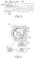
- a camera 10 in which one aspect of the present invention is embodied, is comprised of a camera body 11 and a hinged back cover 20.
- Camera body 11 is conventionally provided with a film cartridge receiving chamber 12, a film frame exposure aperture 14, film take-up chamber 16 and film take-up spool 18.
- Perforation sensing means for film metering in the camera may comprise a light emitting LED 21 mounted in the camera body 11 adjacent exposure aperture 14 and a light sensor 22 mounted on camera back 20 such that when back 20 is closed sensor 22 is aligned with LED 21.
- a film drive motor 52 (Fig.
- Terminals 26 are positioned on the curved surface of cartridge receiving chamber 12. Terminals 26 may be of the type conventionally found in cameras adapted to sense DX codes imprinted on the sides of a film cartridge for the purpose of inputting data to the camera concerning characteristics of the film in the cartridge.
- a film cartridge 30 comprising a generally cylindrical housing 32 enclosing a roll of film 34 wound on an internal spool having an end drive spindle 36 extending out one end of the cartridge.
- the cartridge is provided with resistance means on the outer surface of the cartridge comprised of one or more resistive elements 38 formed of a material normally having a first resistance value and responsive to an applied electrical stimulus to change to a second resistance value.
- a material suitable for this purpose is a carbon or silver based resistive material identified as Conductive Silver Ink 2512 produced and sold by Metech, Inc. of Elverson, Pennsylvania.
- the carbon based version from the same supplier is identified as Flexible Carbon Conductor 2513.
- the cartridge further includes a plurality of terminals 40 on the outer surface of the cartridge in electrical contact with the one or more resistive elements 38.
- the terminals 40 on the cartridge are adapted to be aligned with and make electrical contact with the terminals 26 in the camera cartridge receiving chamber.
- One or more thermo-responsive visual indicator elements 42 are coated over discrete ones of the resistive elements 38.
- These visual indicator elements are preferably formed of a material adapted to change a visual characteristic thereof in response to an increase of heat emitted from the underlying resistive element during the change of resistance value of the resistive element.
- the visual indication may take the form of changing the color of the material, such as from green to red, or it may be a change of optical density from opaque to clear.
- a suitable material for this purpose would be a material sold under the name Thermax Irreversible Temperature Indicating Inks produced and sold by Thermographic Measurements, Inc. of Anaheim, California. These materials have the property of changing color in response to applied heat.
- An alternative preferred embodiment is a material produced and sold by the same company under the name Thermax Irreversible Indicators. These indicators are comprised of a colored substrate overcoated with an opaque specific melt material that melts in response to applied heat and is absorbed into the substrate. In the case of the latter indicator the colored substrate may comprise a printed letter to provide additional indication of the film usage condition. For example, as seen in Fig.
- the letter “E” may be printed underneath an element so that when exposed it would indicate that the film in the cartridge is fully exposed.
- Another visual indicator might have the letter “P” printed underneath so that, when exposed, it would indicate that the film is partially exposed in the cartridge.
- the letters could be printed adjacent the elements as shown in Fig. 2.
- the resistive elements, contact terminals and visual indicator elements may be coated or printed directly onto the outer surface of the film cartridge or they may be coated or printed onto a flexible substrate so as to form a label 46 that could be adhesively applied to the cartridge surface at a suitable stage in the film cartridge production and film loading process.
- contact terminals 26 in the camera receiving chamber are connected to a camera controller 48 to provide suitable inputs to the controller.
- the camera controller is connected to a motor drive circuit 50 used to drive the camera drive motor 52 to control film drive operations in the camera.
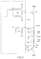
- Fig. 5 there is shown, schematically, the electrical circuit formed by the resistive elements 38a,38b on the cartridge 30 and associated input and output circuits 56,58, respectively, the latter being typically found in camera controller 48.
- the two electrical contract terminals 40 connected to the resistive element 38a under the fully exposed film condition indicator 42a are respectively connected on one side of the element to ground and, on the other side, jointly to a controller input circuit 56 and to the emitter of a normally off switching transistor 60.
- the collector of transistor 60 is connected to a battery normally found in an electronically controlled camera.
- the base of transistor 60 is connected to an output circuit 58 in the controller 48.
- the resistance of resistive element 38a is at its normal low value and the ground potential applied to the controller input circuit 38a allows the drive motor to load the film into the camera.
- the output circuit 58 is caused to output a low condition to the base of transistor 60 thereby driving transistor 60 to conduction and applying the positive battery potential to resistive element 38a.
- the nature of the material used for the resistive element 38a is such that the relatively high battery-induced current through the material is sufficient to cause the resistance of the material to change substantially. It might rise to a high level or could even be driven to an open circuit condition in a manner similar to the operation of a fuse link.
- the heat generated in resistive element 38a during the momentary change in resistive value causes the thermo-responsive material of visual indicator element 42a to respond with either a color change or a change in density, depending on the nature of the material.
- the high or open circuit resistance value of the resistive element 38a would cause a high level input from the internal source V cc to be sensed by input circuit 56, resulting in the sending of a signal to controller 48 indicating that the film in this cartridge is fully exposed.
- the suitably programmed controller would then cause loading of the film to be inhibited, thus preventing double exposure of the film.
- controller 48 sends an output on line 62 to cause the resistive element 38b to change its resistance value in the same manner as described above.
- the changed resistance value of element 38b is sensed by the input circuit on input line 64 and the controller is programmed to initiate loading of the film so as to place the next available unexposed frame in the camera exposure aperture.
Landscapes
- Physics & Mathematics (AREA)
- General Physics & Mathematics (AREA)
- Exposure Control For Cameras (AREA)
- Details Of Cameras Including Film Mechanisms (AREA)
Applications Claiming Priority (2)
| Application Number | Priority Date | Filing Date | Title |
|---|---|---|---|
| US115283 | 1993-08-31 | ||
| US08/115,283 US5351101A (en) | 1993-08-31 | 1993-08-31 | Photographic camera and film cartridge with double exposure prevention |
Publications (1)
| Publication Number | Publication Date |
|---|---|
| EP0640867A1 true EP0640867A1 (de) | 1995-03-01 |
Family
ID=22360359
Family Applications (1)
| Application Number | Title | Priority Date | Filing Date |
|---|---|---|---|
| EP94113104A Withdrawn EP0640867A1 (de) | 1993-08-31 | 1994-08-23 | Photographische Kamera und Filmpatrone ausgerüstet mit einer Vorrichtung zur Verhinderung von Doppelbelichtung |
Country Status (3)
| Country | Link |
|---|---|
| US (1) | US5351101A (de) |
| EP (1) | EP0640867A1 (de) |
| JP (1) | JPH07168237A (de) |
Families Citing this family (2)
| Publication number | Priority date | Publication date | Assignee | Title |
|---|---|---|---|---|
| US5557359A (en) * | 1993-06-17 | 1996-09-17 | Nikon Corporation | Camera including shutter control and method |
| US5717972A (en) * | 1996-12-19 | 1998-02-10 | Eastman Kodak Company | Photographic medium cartridge with chemically activated status indicator |
Citations (6)
| Publication number | Priority date | Publication date | Assignee | Title |
|---|---|---|---|---|
| JPS5695232A (en) * | 1979-12-28 | 1981-08-01 | Konishiroku Photo Ind Co Ltd | Camera with color balance correcting device |
| US4707806A (en) * | 1984-03-23 | 1987-11-17 | Fujitsu Limited | Semiconductor integrated circuit device having fuse-type information storing circuit |
| EP0344916A1 (de) * | 1988-05-02 | 1989-12-06 | Nikon Corporation | Informationsaufzeichnungssystem |
| JPH023364A (ja) * | 1988-06-20 | 1990-01-08 | Nec Ic Microcomput Syst Ltd | 熱転写方式カラープリンタ |
| EP0581349A2 (de) * | 1992-07-10 | 1994-02-02 | Koninklijke Philips Electronics N.V. | System zur Aufnahme und/oder Wiedergabe von Informationssignalen und Kassette und Gerät für das System |
| US5285227A (en) * | 1993-03-16 | 1994-02-08 | Eastman Kodak Company | Photographic camera and film cartridge with double exposure prevention |
Family Cites Families (4)
| Publication number | Priority date | Publication date | Assignee | Title |
|---|---|---|---|---|
| EP0414269B1 (de) * | 1989-08-25 | 1995-03-08 | Fuji Photo Film Co., Ltd. | Kassette für einen fotografischen Film |
| US5032854A (en) * | 1990-07-31 | 1991-07-16 | Eastman Kodak Company | Photographic film cassette and camera apparatus and method |
| US5047794A (en) * | 1990-07-31 | 1991-09-10 | Eastman Kodak Company | Film cassette with lock-out means for preventing load of exposed film |
| US5030978A (en) * | 1990-09-12 | 1991-07-09 | Eastman Kodak Company | Photographic film cassette |
-
1993
- 1993-08-31 US US08/115,283 patent/US5351101A/en not_active Expired - Fee Related
-
1994
- 1994-08-23 EP EP94113104A patent/EP0640867A1/de not_active Withdrawn
- 1994-08-30 JP JP6204871A patent/JPH07168237A/ja active Pending
Patent Citations (6)
| Publication number | Priority date | Publication date | Assignee | Title |
|---|---|---|---|---|
| JPS5695232A (en) * | 1979-12-28 | 1981-08-01 | Konishiroku Photo Ind Co Ltd | Camera with color balance correcting device |
| US4707806A (en) * | 1984-03-23 | 1987-11-17 | Fujitsu Limited | Semiconductor integrated circuit device having fuse-type information storing circuit |
| EP0344916A1 (de) * | 1988-05-02 | 1989-12-06 | Nikon Corporation | Informationsaufzeichnungssystem |
| JPH023364A (ja) * | 1988-06-20 | 1990-01-08 | Nec Ic Microcomput Syst Ltd | 熱転写方式カラープリンタ |
| EP0581349A2 (de) * | 1992-07-10 | 1994-02-02 | Koninklijke Philips Electronics N.V. | System zur Aufnahme und/oder Wiedergabe von Informationssignalen und Kassette und Gerät für das System |
| US5285227A (en) * | 1993-03-16 | 1994-02-08 | Eastman Kodak Company | Photographic camera and film cartridge with double exposure prevention |
Non-Patent Citations (2)
| Title |
|---|
| PATENT ABSTRACTS OF JAPAN vol. 14, no. 132 (M - 0948) 13 March 1990 (1990-03-13) * |
| PATENT ABSTRACTS OF JAPAN vol. 5, no. 165 (P - 085) 22 October 1981 (1981-10-22) * |
Also Published As
| Publication number | Publication date |
|---|---|
| US5351101A (en) | 1994-09-27 |
| JPH07168237A (ja) | 1995-07-04 |
Similar Documents
| Publication | Publication Date | Title |
|---|---|---|
| EP0344916B1 (de) | Informationsaufzeichnungssystem | |
| EP0601423B1 (de) | Kameramechanismus und Methode zur Verhinderung der Doppelbelichtung eines Films | |
| JPH04119353A (ja) | 写真フイルムパトローネ | |
| US5502529A (en) | Method of recycling single-use camera | |
| EP0051630B1 (de) | Verfahren zur Rückstellung eines elektrisch betätigten Speichers einer photographischer Kamera und solche Kamera | |
| US4751546A (en) | Display device for cameras | |
| US5285227A (en) | Photographic camera and film cartridge with double exposure prevention | |
| US4579432A (en) | Automatic film rewinding device | |
| US5351101A (en) | Photographic camera and film cartridge with double exposure prevention | |
| US5778265A (en) | Camera allowing setting of print number | |
| US5717968A (en) | Format indicating daylight camera, optical writing system, and method for recycling single use cameras | |
| US5895135A (en) | Photographic camera | |
| EP0676061B1 (de) | Verfahren und vorrichtung zur einstellung der kamera betriebsweise | |
| US6061530A (en) | Camera having a facility for changing information recorded on film | |
| US6424806B1 (en) | Camera having interlock preventing simultaneous use of electronic zoom and panoramic format | |
| US6411779B1 (en) | Lens-fitted photo film unit having IC | |
| US5815752A (en) | Camera having a magnetic recording apparatus selectively operable based on film feed speed | |
| US6144806A (en) | Camera having data protection means | |
| JP3141064B2 (ja) | カメラ | |
| JP3406870B2 (ja) | データ写し込み機能付きカメラ | |
| JPH07333675A (ja) | フィルム情報読取装置 | |
| JPH1184591A (ja) | 内視鏡用フィルムカセット | |
| JPH08334819A (ja) | データ写し込みカメラ | |
| JPH06110119A (ja) | コピーライト記録装置 | |
| JPH086103A (ja) | フィルム情報読取装置 |
Legal Events
| Date | Code | Title | Description |
|---|---|---|---|
| PUAI | Public reference made under article 153(3) epc to a published international application that has entered the european phase |
Free format text: ORIGINAL CODE: 0009012 |
|
| AK | Designated contracting states |
Kind code of ref document: A1 Designated state(s): DE FR GB |
|
| 17P | Request for examination filed |
Effective date: 19950802 |
|
| 17Q | First examination report despatched |
Effective date: 19981221 |
|
| GRAG | Despatch of communication of intention to grant |
Free format text: ORIGINAL CODE: EPIDOS AGRA |
|
| STAA | Information on the status of an ep patent application or granted ep patent |
Free format text: STATUS: THE APPLICATION HAS BEEN WITHDRAWN |
|
| 18W | Application withdrawn |
Withdrawal date: 19990510 |