EP0640825B1 - Verfahren und Vorrichtung zum Analyse von porösen Stoffen - Google Patents
Verfahren und Vorrichtung zum Analyse von porösen Stoffen Download PDFInfo
- Publication number
- EP0640825B1 EP0640825B1 EP94810473A EP94810473A EP0640825B1 EP 0640825 B1 EP0640825 B1 EP 0640825B1 EP 94810473 A EP94810473 A EP 94810473A EP 94810473 A EP94810473 A EP 94810473A EP 0640825 B1 EP0640825 B1 EP 0640825B1
- Authority
- EP
- European Patent Office
- Prior art keywords
- collecting
- extracting
- extracting fluid
- fluid
- extract
- Prior art date
- Legal status (The legal status is an assumption and is not a legal conclusion. Google has not performed a legal analysis and makes no representation as to the accuracy of the status listed.)
- Expired - Lifetime
Links
- 239000011148 porous material Substances 0.000 title claims abstract description 28
- 238000000034 method Methods 0.000 title claims abstract description 23
- 238000004458 analytical method Methods 0.000 title claims description 14
- 239000012530 fluid Substances 0.000 claims abstract description 55
- 239000000463 material Substances 0.000 claims abstract description 48
- 239000000126 substance Substances 0.000 claims abstract description 23
- 239000004753 textile Substances 0.000 claims abstract description 23
- 239000000284 extract Substances 0.000 claims abstract description 21
- 238000000605 extraction Methods 0.000 claims description 27
- 230000004888 barrier function Effects 0.000 claims description 13
- 239000007788 liquid Substances 0.000 claims description 12
- 238000010438 heat treatment Methods 0.000 claims description 11
- 238000003795 desorption Methods 0.000 claims description 5
- 230000009467 reduction Effects 0.000 claims description 5
- 229910052751 metal Inorganic materials 0.000 claims description 4
- 239000002184 metal Substances 0.000 claims description 4
- 238000003825 pressing Methods 0.000 claims description 3
- 238000003860 storage Methods 0.000 claims description 3
- 239000003960 organic solvent Substances 0.000 claims description 2
- 238000009835 boiling Methods 0.000 claims 1
- 239000000835 fiber Substances 0.000 claims 1
- 239000000523 sample Substances 0.000 description 15
- XLYOFNOQVPJJNP-UHFFFAOYSA-N water Substances O XLYOFNOQVPJJNP-UHFFFAOYSA-N 0.000 description 12
- 229910000831 Steel Inorganic materials 0.000 description 7
- 239000002904 solvent Substances 0.000 description 7
- 239000010959 steel Substances 0.000 description 7
- 239000003795 chemical substances by application Substances 0.000 description 5
- 239000000203 mixture Substances 0.000 description 5
- PXHVJJICTQNCMI-UHFFFAOYSA-N Nickel Chemical compound [Ni] PXHVJJICTQNCMI-UHFFFAOYSA-N 0.000 description 4
- 239000002253 acid Substances 0.000 description 4
- 150000007513 acids Chemical class 0.000 description 4
- 239000004744 fabric Substances 0.000 description 4
- 239000000758 substrate Substances 0.000 description 4
- OKKJLVBELUTLKV-UHFFFAOYSA-N Methanol Chemical compound OC OKKJLVBELUTLKV-UHFFFAOYSA-N 0.000 description 3
- ZMXDDKWLCZADIW-UHFFFAOYSA-N N,N-Dimethylformamide Chemical compound CN(C)C=O ZMXDDKWLCZADIW-UHFFFAOYSA-N 0.000 description 3
- 239000007789 gas Substances 0.000 description 3
- 238000005070 sampling Methods 0.000 description 3
- CSCPPACGZOOCGX-UHFFFAOYSA-N Acetone Chemical compound CC(C)=O CSCPPACGZOOCGX-UHFFFAOYSA-N 0.000 description 2
- CURLTUGMZLYLDI-UHFFFAOYSA-N Carbon dioxide Chemical compound O=C=O CURLTUGMZLYLDI-UHFFFAOYSA-N 0.000 description 2
- VYZAMTAEIAYCRO-UHFFFAOYSA-N Chromium Chemical compound [Cr] VYZAMTAEIAYCRO-UHFFFAOYSA-N 0.000 description 2
- IAZDPXIOMUYVGZ-UHFFFAOYSA-N Dimethylsulphoxide Chemical compound CS(C)=O IAZDPXIOMUYVGZ-UHFFFAOYSA-N 0.000 description 2
- LFQSCWFLJHTTHZ-UHFFFAOYSA-N Ethanol Chemical compound CCO LFQSCWFLJHTTHZ-UHFFFAOYSA-N 0.000 description 2
- 239000002585 base Substances 0.000 description 2
- 238000006243 chemical reaction Methods 0.000 description 2
- 229910052804 chromium Inorganic materials 0.000 description 2
- 239000011651 chromium Substances 0.000 description 2
- 230000006378 damage Effects 0.000 description 2
- 238000009434 installation Methods 0.000 description 2
- 238000004519 manufacturing process Methods 0.000 description 2
- 230000007246 mechanism Effects 0.000 description 2
- 229910052759 nickel Inorganic materials 0.000 description 2
- 238000004513 sizing Methods 0.000 description 2
- 239000000243 solution Substances 0.000 description 2
- 125000006850 spacer group Chemical group 0.000 description 2
- RYHBNJHYFVUHQT-UHFFFAOYSA-N 1,4-Dioxane Chemical compound C1COCCO1 RYHBNJHYFVUHQT-UHFFFAOYSA-N 0.000 description 1
- 229920003043 Cellulose fiber Polymers 0.000 description 1
- RYGMFSIKBFXOCR-UHFFFAOYSA-N Copper Chemical compound [Cu] RYGMFSIKBFXOCR-UHFFFAOYSA-N 0.000 description 1
- 229910000881 Cu alloy Inorganic materials 0.000 description 1
- 238000010521 absorption reaction Methods 0.000 description 1
- 230000006978 adaptation Effects 0.000 description 1
- 239000000654 additive Substances 0.000 description 1
- 150000001298 alcohols Chemical class 0.000 description 1
- 239000003513 alkali Substances 0.000 description 1
- 150000001408 amides Chemical class 0.000 description 1
- 239000012736 aqueous medium Substances 0.000 description 1
- 239000007864 aqueous solution Substances 0.000 description 1
- 239000001569 carbon dioxide Substances 0.000 description 1
- 229910002092 carbon dioxide Inorganic materials 0.000 description 1
- 229910052802 copper Inorganic materials 0.000 description 1
- 239000010949 copper Substances 0.000 description 1
- 239000008367 deionised water Substances 0.000 description 1
- 229910021641 deionized water Inorganic materials 0.000 description 1
- 230000001066 destructive effect Effects 0.000 description 1
- 238000001035 drying Methods 0.000 description 1
- 238000004043 dyeing Methods 0.000 description 1
- 230000000694 effects Effects 0.000 description 1
- 239000000839 emulsion Substances 0.000 description 1
- 150000002148 esters Chemical class 0.000 description 1
- 150000002170 ethers Chemical class 0.000 description 1
- 238000005470 impregnation Methods 0.000 description 1
- 238000002347 injection Methods 0.000 description 1
- 239000007924 injection Substances 0.000 description 1
- 150000002500 ions Chemical class 0.000 description 1
- 150000002576 ketones Chemical class 0.000 description 1
- 238000009940 knitting Methods 0.000 description 1
- 238000005259 measurement Methods 0.000 description 1
- 239000002609 medium Substances 0.000 description 1
- 239000004745 nonwoven fabric Substances 0.000 description 1
- 238000004886 process control Methods 0.000 description 1
- 239000011347 resin Substances 0.000 description 1
- 229920005989 resin Polymers 0.000 description 1
- 239000004094 surface-active agent Substances 0.000 description 1
- 238000009834 vaporization Methods 0.000 description 1
- 230000008016 vaporization Effects 0.000 description 1
- 238000005406 washing Methods 0.000 description 1
- 238000009941 weaving Methods 0.000 description 1
- 238000003466 welding Methods 0.000 description 1
- 239000002759 woven fabric Substances 0.000 description 1
- -1 woven knittings Substances 0.000 description 1
Images


Classifications
-
- G—PHYSICS
- G01—MEASURING; TESTING
- G01N—INVESTIGATING OR ANALYSING MATERIALS BY DETERMINING THEIR CHEMICAL OR PHYSICAL PROPERTIES
- G01N33/00—Investigating or analysing materials by specific methods not covered by groups G01N1/00 - G01N31/00
- G01N33/36—Textiles
-
- G—PHYSICS
- G01—MEASURING; TESTING
- G01N—INVESTIGATING OR ANALYSING MATERIALS BY DETERMINING THEIR CHEMICAL OR PHYSICAL PROPERTIES
- G01N1/00—Sampling; Preparing specimens for investigation
- G01N1/28—Preparing specimens for investigation including physical details of (bio-)chemical methods covered elsewhere, e.g. G01N33/50, C12Q
- G01N1/34—Purifying; Cleaning
-
- G—PHYSICS
- G01—MEASURING; TESTING
- G01N—INVESTIGATING OR ANALYSING MATERIALS BY DETERMINING THEIR CHEMICAL OR PHYSICAL PROPERTIES
- G01N1/00—Sampling; Preparing specimens for investigation
- G01N1/28—Preparing specimens for investigation including physical details of (bio-)chemical methods covered elsewhere, e.g. G01N33/50, C12Q
- G01N1/40—Concentrating samples
- G01N1/4055—Concentrating samples by solubility techniques
- G01N2001/4061—Solvent extraction
Definitions
- the present invention refers to a device or apparatus for the analysis of porous materials which contain extractable substances, in order to determine the inner condition of the material, such as substances present in or on the material, by forced desorption and extraction. More particularly, this invention is directed to the analysis of textile materials, especially of such materials in sheet or web form, but also in the form of parallel strands of filaments, by means of water, aqueous liquids, or organic solvents.
- analysis means the determination of the condition within materials as defined above but also, more generally, the determination of substances contained in or on porous materials.
- European patent application No. EP-A2-0,529,455 discloses a method and a device for the continuous measurement of the presence of ionic and nonionic substances in a running textile material web. For example, a solvent is sprayed or otherwise applied from one side onto a definite region of the running web, and the solvent or the solution draining through the textile material is collected from the other side of the web.
- This method and device only supplies rough values since there are no definite conditions: part of the solvent necessarily remains in the web by absorption.
- the solvent is applied by a moving device, and there is no certainty whether the amount of solvent used throughout the application surface is uniform or not.
- relatively huge amounts of extracting solvents must be used which yield only very diluted extracts.
- the method cannot be used on dry textile material.
- the first and major object of the present invention is to provide an apparatus which allows the exact and rapid extraction of flat, porous materials, particularly textile materials, so that the inner condition of the materials can rapidly and exacty be determined.
- Another object of the invention is to provide a method as depicted above which, during extraction of the porous material, creates certain conditions and states which are reproducibly defined and which, on the other hand, allow a complete, quantitative desorption of extractible substances from the porous substrate to be assayed.
- Still another object of the present invention is to provide a method of extraction and collection of the extracted fluids by means of the apparatus according to this invention, which yields liquid samples quantitatively representing the inner condition of the substrate that can easily and rapidly be assayed by using only small volumes of extracting fluid.
- the apparatus of the present invention comprises a pressure element and a collecting element both having a central axis, said axes being aligned to each other, said elements being fastened to a support system comprising two parallel support beams, and the apparatus further comprises means for pressing the two said elements together in clamping the said porous material between them, and means for the supply of extraction liquid and for recovering and collecting the extract from the porous material.
- the apparatus of the invention may be used in principle with any porous materials whatsoever having open pores which allow the passage of fluids and in which substances are enclosed which can be taken up by the said fluid which is the extraction medium and be carried out of the materials; two-dimensional, i.e. sheet or web like materials being preferred.
- the extraction fluid may very easily be adapted to the nature, particularly the solubility, of the substances expected within the porous materials.
- water is used, for example deionized water, which will be heated in the apparatus of the invention to about 70 to 100 °C, preferably to about 90 to 95 °C.
- Aqueous solutions may also be used; an example is the use of diluted alkali for the extraction of acids without losses and with more ease.
- extraction fluids examples include condensing steam, mixtures of steam and water, mixtures of air or other gases with water, mixtures of water and carbon dioxide, mixtures of water with organic liquids which need not be soluble in water such as alcohols, ketones, amides, ethers, esters, acids, bases, all these liquids being optionally mixed with steam or other vapours and gases, emulsions of water with water insoluble or partially soluble liquids, dimethyl sulfoxide, dimethyl formamide and non-aqueous liquids such as methanol, ethanol, acetone, dioxane, etc. This listing is by no means exhaustive.
- the extracting fluid may further contain additives such as surface active agents.
- an aqueous base will be used as an extraction fluid which preferably extracts the acids.
- warm or hot extraction fluids sometimes even superheated ones, the apparatus of the invention allows also cold extraction processes.
- the porous materials to be extracted may be those already mentioned above. Textile materials are particularly important, such as webs or clothes of woven fabrics, woven knittings, non-wovens, pole fabrics, etc.
- the invention allows an analysis of enclosed substances without destruction or damage of the material and is particularly suited for the use in test and industrial laboratories since only small volumes of extraction fluid are used and the very analysis may be executed very rapidly.
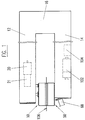
- the apparatus which is schematically shown in FIGURE 1 comprises two main parts, namely the sampling device comprising the appertaining driving parts, and a control and display device (not shown) which contains the necessary control devices and display elements; all these devices and elements (not shown, but familiar to the one skilled in the art) are mounted in a control cabinet which is not shown either.
- the sampling device comprises two major parts, namely the pressure element 10, called also upper shoe, and the extracting and collecting element or lower shoe 50; these elements will be described in detail later.
- Both elements are disposed at the front end of support bars 12 and 14, respectively, which are rigidly connected to each other at their rear ends by a traverse 16, e.g. by welding.
- the support bars 12 and 14 are hollow profiles in the shown embodiment and can therefore contain other elements of the apparatus.
- the free length of the support bars 12 and 14 is selected such that they are adapted to the width of a web 106 of a porous sheet material to be analyzed, generally a textile material, see below. As it is further shown in FIGURE 1, the material 106 is clamped between elements 10 and 50.
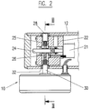
- a gear box 22 is mounted in the interior of the bar 12.
- An electric motor 20 comprising a reduction gear 21 is flanged to the gear box 22; in the present example, a d.c. minimotor for 12 volts, having a power of 6.8 watts and a speed of 4500 rpm, was used.
- An eccenter disk 26 which acts upwards through a bearing 27 on a setting screw 28 is solidly fastened on the output shaft 24 of reduction gear 21.
- the eccenter disk 26 acts downwards through bearing 27 on a pin 30 which is movable in the vertical direction and which extends through a bushing 32 in a bore in support bar 12.
- a connecting disk is referenced by numeral 25 which circumferentially connects both elements 28 and 30.
- pin 30 is connected over a bushing 34 to a circular steel plate 36 which has in the present example a diameter of about 80 to 85 millimeters.
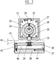
- a circular pressure plate 38 is bolted with a certain distance to steel plate 36, and FIGURE 3 shows one of several screws 41 and spacers 42.
- the space between steel plate 36 and pressure plate 38 is closed by an annular cover 37.
- Pressure plate 38 consists of a highly heat conductive metal, e.g. copper or a copper alloy; its lower surface and, optionally, its other outer surfaces are high-polished chromium or nickel plated.
- the pressure plate 38 can be heated by means of a flat circular heating sheet 40 cemented on the inner surface of the plate; if an aqueous medium is used as an extraction fluid, the plate may be heated to a temperature of, e.g., 90 to 98 °C.
- the heating power of the heating sheet 40 is controlled by means of a temperature probe, for example a Ni-CrNi-thermocouple 44, which is inserted into a horizontal bore of the pressure plate 38, in such a manner that the temperature of the pressure plate is maintained at the desired value.
- the thermocouple acts simultaneously as a temperature controlling and a temperature measuring device, i.e. a thermometer.
- the stroke of the eccenter disk 26 is designed in such a manner that the pressure plate 38 exerts a predetermined pressure or force on the substrate, for example about 1000 N corresponding, with the surface area to be considered, to a pressure of 1 to 2 bars.
- FIGURE 4 shows a vertical sectional view of the extracting and collecting element 50. It comprises a steel plate 52 having the shape of a circular disk and mounted on the front end of lower support bar 14. The plate has a central bore 54 traversed by two conduits 56A and 57. Furthermore, a lateral bore 58 is provided giving a passage for the extracting fluid supply tube 60.
- a lower block 62 is fastened from below to the support bar 14 and the steel plate 52 by means of screws 64.
- the lower block 62 which is held against the lower rail 14A of the support bar 14 by a supporting and distance block 63 has an angular bore 66 whose longitudinal axis is at an angle of about 20° to the horizontal plane.
- a sample tube 68 having a corresponding diameter can be inserted into the bore 66 and is sealed against the wall of the bore by one or more O-rings 72.
- the main collecting conduit 56 as well as a suction tube 74 open into the sample tube 68.
- a lower pressure plate 78 is disposed in a distance from the steel plate 52 above the latter by means of an annular spacer 76 which is inserted into annular grooves of the lower steel plate 52 and the lower pressure plate 78 and fastened to the respective plates by screws (not shown).
- the lower pressure plate 78 has substantially the same dimensions as the upper pressure plate 38 of the upper shoe 10. It is also made of superficially chromium or nickel plated and mirror-polished copper in order to ascertain a good heat conductivity and capacity.
- the lower pressure plate has a central bore 80 which is connected to a flat metal spiral tube 88. This flat spiral 88 contacts and is mounted on the lower, free surface of a flat, circular heating element 90 which corresponds in principle to the upper heating element 40. The permanent contact with the heating element 90 continuously heats the spiral tube 88 to the desired temperature.
- the lower pressure plate 78 further contains, as in the case of the upper pressure plate 38, a thermocouple 92 for controlling the temperature of the plate 78 as it has already been described with reference to the element 44. The temperature of plate 78 should be the same as that of the upper pressure plate 38.
- the thermocouple 92 is preferably also a Ni-CrNi element.
- a supply tank 104 for extraction fluid 105 for example a bottle, is lodged within the lower support bar 14 (see also FIGURE 1).
- An extracting and collecting mechanism 102 is also located in the lower bar 14.
- This mechanism comprises an electromotor 107 flanged to a reduction gearbox 108.
- the output shaft 109 of the reduction gearbox 108 is threaded so that the shaft makes a reciprocating movement when the motor 107 turns in one and in the other sense of rotation.
- a piston 110 sliding in a cylinder 111 is fastened to the right end (FIGURE 4) of the output shaft 109.
- a bridge or yoke 112 to which two piston rods 113 and 114 are fastened is fixed to the left free end of the output shaft 109; these two piston rods 113, 114 carry pistons 115 and 116, respectively, which slide in cylinders 117 and 118, respectively.
- the bottom of cylinder 111 is connected by conduit 74 to the sample tube 68.
- the bottom of each cylinder 117 and 118 is connected to a three-way valve 119 and 120, respectively.
- the two three-way valves 119, 120 are connected by a conduit 121A, 121B to a combined conduit 121 which leads into the extracting fluid storage vessel 104.
- the third connection of three-way valve 119 is connected by conduit 60 to metal spiral tube 88.
- the third connection of three-way valve 120 is connected to a conduit 122 which leads to lower pressure plate 78; its purpose will be described later.
- the upper surface of the lower pressure plate 78 comprises means for ejecting extracting fluid and for collecting the extract from the porous material clamped between plates 38 and 78.
- FIGURE 5 shows a top view of lower pressure plate 78.
- This surface comprises two circular concentrical grooves 98 and 99.
- Conduits 122 which have already been described above end in barrier groove 99 through several holes 94 which are evenly distributed over the circumference of groove 99.
- Conduits 56 which merge into the main collecting conduit 56A already described, end in collecting groove 98 through several holes 101 which are evenly distributed over the circumference of groove 98.
- conduits 56 and 122 are welded or soldered together in order to obtain a heat exchange between the liquids flowing within the conduits.
- the eccenter disk 26 In the rest position, the eccenter disk 26 has been turned such that the upper pressure shoe 10 is in its uppermost position, and a gap of about 7 to 10 mm is free between the upper shoe 10 and the lower shoe 50.
- the conduits 60 and 122 as well as the cylinders 117 and 118 are in this position already filled with extraction fluid 105 from supply vessel 104, and the three pistons of the extracting device 102 are in the position shown in FIGURE 4.
- the heating elements 40, 90 of the two shoes are energized.
- the desired extraction temperature for example about 95 °C, which requires some minutes only
- motor 20 is energized which lowers the pressure shoe 10 by means of the eccenter disk 26 until the greatest diameter of the eccenter disk acts upon pin 30 and thus on the pressure shoe 10. In this position, a pressing force of about 1'000 Newton is exerted on the fabric 106.
- the setting of the adjusting screw 28 and the elasticity of the two supporting bars 12 and 14 together with its connecting traverse 16 is selected such that the said force is stabilized.
- the free length of the bars 14 and 16 is such that textile materials having current widths can be put between the pressure shoes so that any desired surface region can be analyzed and no region of the textile material remains inaccessible.
- motor 107 of the extracting device 102 is energized from the shown position, and shaft 109 is pushed to the left in FIGURE 4.
- the two three-way valves are in the shown position. From cylinder 117 which has an active volume of about 5 ml, exactly 5 ml of extracting fluid are fed into line 60 so that 5 ml of hot extracting fluid, heated within the spiral conduit 88, are ejected through the opening 80 in the plate 78 into the clamped-in textile material 106 and spread in this substrate according to flow arrows A.
- barrier fluid identical to the extracting fluid, are fed from cylinder 118 through conduit 122 and openings 94 into the barrier groove 99 which is situated near the outer edge of plate 78. 1 ml of fluid will circumferentially escape from the clamped-in sample of web 106 according to flow arrows B.
- the fluids injection is effected during about 20 seconds.
- the extraction fluid flows within the clamped-in textile material sample toward the collecting groove 98 which is concentric to the barrier groove 99 and has a radial distance to the latter of some millimeters.
- extractable substances within the textile material sample are extracted and carried away with the flowing extracting fluid.
- the flow of this fluid from the opening 80 to the collecting groove 98 is assisted by an air suction through conduit 56 and conduit 74 which ends in air suction cylinder 111 whose piston 110 is moved from the right to the left during the corresponding movement of the other two pistons 115 and 116, already described above.
- the extract collects in collecting groove 98 and flows through holes 101 and conduit 56 into the sample tube 68.
- conduit 122 which carries cold fluid from cylinder 118 is thermally connected to conduit 56 in which flows the hot extract to sample tube 68.
- the extract is cooled down to about 55 to 65 °C whereas, in a most desired manner, the barrier fluid flowing through conduit 122 is heated to about 80 °C.
- the two three-way valves 119 and 120 are now turned clockwise by 90°, and the motor 107 is turned on in the inverse sense of rotation.
- the two pistons 115 and 116 are moved to the right until their end position, and the cylinders 117 and 118 are filled with the measured amount of extracting fluid 105 from supply vessel 104 through conduits 121, 121A and 121B.
- the two three-way valves 119 and 120 are rotated conterclockwise by 90° in order to connect the cylinders to conduits 60 and 122, respectively.
- the motor 20 is now energized anew and turns the eccenter disk 26 by 180° so that the upper shoe is lifted by about 7 mm, and another region of the material to be analyzed can be clamped in for extraction. Extracting liquid remains within the spiral tube 88, about 5 ml in the present example, which is at the desired temperature so that the next extraction may immediately begin.
- sample tube 68 is ready to be analyzed.
- sample tube 68 is retracted from the apparatus, stoppered and put into an automatic analyzer or any other manual or automatic analyzing device.
- Such devices are well known to the one skilled in the art and need not be described or shown in the present document.
- interesting parameters to be assayed are pH value, color, conductivity, presence and, optionally, amount of certain ions and/or organic substances such as sizing agents, surface tension, viscosity, redox potential, residues and so on.
- the apparatus of the invention which has been described generally comprises still other elements, parts and units which are not shown.
- the process steps described above are preferably run according to an automatic program which may be invariable or adjustable.
- the steps, operations and actions are preferably displayed.
- These additional parts and elements are well known to the one skilled in the art and will not be described herein.
- the apparatus may be diversely modified and adapted to special problems and purposes and conditions of use. For example, it is possible to exchange the pressure and collecting parts, to make the lower shoe vertically displaceable instead of or in addition to the upper shoe.
- the two shoes may alternatively be pressed together by pneumatic or hydraulic devices by mounting corresponding driving elements which are known per se.
- the present invention provides an apparatus for the execution of a rapid method for the determination of the inner condition of a sheet-like, porous material, in particular of a textile material web, by forced desorption, solution and/or extraction of substances from said material.
- the sampling requires generally not more than 30 to 60 seconds, and measuring values can be obtained which can immediately be translated into corresponding adaptations of production parameters.
- the apparatus is a compact and transportable unit which can be approached to any sheet or web like material; therefore, it is no longer necessary to cut pieces or other samples from the sheet and to bring them into a laboratory. It is neither necessary to mount the apparatus into finishing machines or installations in order to obtain extracted samples. It is further possible to equip the apparatus of the invention with a battery powered electric supply which further improves the application possibilities.
- sample tube described above may be replaced by a similar receptacle which is directly connected to an analyzing apparatus or installation; in this case, the analysis may be effected nearly simultaneously with the extraction, and this will provide the analysis data still more rapidly.
- a process control could directly be influenced by the analysis results.
Landscapes
- Life Sciences & Earth Sciences (AREA)
- Health & Medical Sciences (AREA)
- Chemical & Material Sciences (AREA)
- Engineering & Computer Science (AREA)
- Pathology (AREA)
- Immunology (AREA)
- Physics & Mathematics (AREA)
- Analytical Chemistry (AREA)
- Biochemistry (AREA)
- General Health & Medical Sciences (AREA)
- General Physics & Mathematics (AREA)
- Molecular Biology (AREA)
- Biomedical Technology (AREA)
- Textile Engineering (AREA)
- Food Science & Technology (AREA)
- Medicinal Chemistry (AREA)
- Sampling And Sample Adjustment (AREA)
- Analysing Materials By The Use Of Radiation (AREA)
- Treatment Of Fiber Materials (AREA)
Claims (21)
- Vorrichtung zur Analyse extrahierbare Substanzen enthaltender poröser Materialien (106), um den inneren Zustand des Materials einschliesslich Substanzen, die in oder auf dem Material vorhanden sind, durch erzwungene Desorption und Extraktion zu bestimmen, wobei die Vorrichtunga) ein Druckelement (10) und ein Sammelelement (50), welche einander zugewandte Berührungsflächen aufweisen und koaxial angeordnet und an einem Tragbalkensystem befestigt sind, das aus zwei parallelen Tragbalken (12, 14) mit oberen und unteren Oberflächen besteht,b) Mittel zum Anpressen der genannten zwei Elemente aneinander, wobei das genannte poröse Material zwischen den Berührungsflächen der genannten Elemente eingeklemmt wird,c) Mittel zum Einbringen eines Extraktionsfluids durch eines der genannten Elemente in das eingeklemmte Material, undd) Mittel zum Abführen eines Extrakts, der aus dem genannten Extraktionsfluid und aus dem genannten Material extrahierten Substanzen besteht, und zum Auffangen des Extrakts
aufweist. - Vorrichtung nach Anspruch 1, worin die genannten beiden Elemente (10, 50) die Form kreisförmiger Scheiben haben und jedes Element eine kreisförmige Druckplatte (38, 78) mit einer Heizvorrichtung (40, 90) aufweist und jede Druckplatte mit axialem Abstand an einer kreisförmigen Aufbauplatte (36, 52) aus einem dimensionsstabilen Metall befestigt ist, wobei alle genannten Platten im wesentlichen den gleichen Durchmesser aufweisen.
- Vorrichtung nach Anspruch 1, enthaltend weiterhin Absaugemittel (110, 111, 101) zum Abziehen des gebildeten Extrakts aus dem genannten eingeklemmten porösen Material.
- Vorrichtung nach Anspruch 2, worin das Druckelement (10) an der unteren Fläche des ersten, oberen Tragbalkens (12) und das Sammelelement (50) an der oberen Fläche des zweiten, unteren Tragbalkens (14) befestigt ist.
- Vorrichtung nach Anspruch 2, worin die Heizvorrichtungen (40, 90) der beiden genannten Druckplatten flache, blattförmige kreisrunde Heizelemente sind, welche an der inneren Oberfläche der genannten Druckplatten angebracht sind.
- Vorrichtung nach Anspruch 5, worin die genannten Druckplatten weiterhin Mittel (44, 92) zur Messung und Regelung der Temperatur der genannten Platten aufweisen.
- Vorrichtung nach Anspruch 4, worin das Sammelelement (50) mit dem genannten unteren Tragbalken starr verbunden und das Druckelement (10) am genannten oberen Tragbalken (12) axial verschiebbar befestigt ist, um gegen das Sammelelement gedrückt zu werden.
- Vorrichtung nach Anspruch 7, worin sich im oberen Tragbalken (12) ein Antriebsmotor (20) befindet, der mit einem Reduktionsgetriebe (21) mit Abtriebswelle (24) verbunden ist, auf welcher eine Exzenterscheibe (26) angebracht ist, die auf einen Stift (30) wirkt, der mit dem genannten Druckelement (10) in Verbindung steht, um das genannte Druckelement zum genannten Sammelelement (50) hin und wieder zurück zu bewegen.
- Vorrichtung nach Anspruch 2, worin die äussere Fläche der Druckplatte (78) des genannten Sammelelements mit einer mittigen Bohrung (80) zur Zufuhr von frischem Extraktionsfluid, einer ersten, kreisrunden Sammelnut (98) nahe am Aussenrand der Druckplatte zum Sammeln des Extrakts und einer zweiten, kreisrunden Sperrnut (99) versehen ist, welche zwischen der genannten ersten Nut (98) und dem Aussenrand der genannten Druckplatte (78) verläuft, wobei beide Nuten Bohrungen (94, 101) aufweisen, die die Druckplatte durchsetzen.
- Vorrichtung nach Anspruch 9, worin die genannten Mittel zur Zufuhr von Extraktionsfluid einen Vorratsbehälter für Extraktionsfluid (104); eine erste Dosiereinrichtung (115, 117, 119) zur Zufuhr abgemessener Volumina an Extraktionsfluid zur mittigen Bohrung (80) des Sammelelements (50); zweite Dosiereinrichtungen (116, 118, 120) zur Zufuhr abgemessener Mengen an Extraktionsfluid zur genannten Sperrnut (99) der Druckplatte; eine heizbare Rohrspirale (88) zum Heizen von Extraktionsfluid, das von der ersten Dosiereinrichtung geliefert wird; und Rohrleitungen (121, 60, 122) zur Verbindung des genannten Vorratsbehälters mit den Dosiereinrichtungen und der letzteren mit der Rohrspirale und der genannten Druckplatte (78) aufweisen.
- Vorrichtung nach Anspruch 9, worin die genannten Mittel zur Abfuhr des genannten Extraktes mehrere Sammelleitungen (56), die mit der genannten Sammelnut (98) verbunden sind und in eine Hauptsammelleitung (56A) münden, und eine Absaugeeinrichtung (110, 111) aufweisen, die über eine Saugleitung (74) mit dem genannten Proberöhrchen verbunden ist, wobei die genannte Hauptsammelleitung in das Proberöhrchen (68) führt.
- Vorrichtung nach Anspruch 10 und 11, worin jede Leitung (122), welche zur Zufuhr des Extraktionsfluids zur Sperrnut (99) von der zweiten Dosiereinrichtung (116, 118, 120) kommt, in engem Wärmeleitungskontakt mit einer Sammelleitung (56) steht, welche von der Sammelnut (98) kommt.
- Verfahren zur Analyse eines porösen Materials, welches extrahierbare Substanzen enthält, um den inneren Zustand des Materials einschliesslich Substanzen zu bestimmen, die in oder auf dem Material vorhanden sind, durch erzwungene Desorption und Extraktion unter Verwendung der Vorrichtung nach einem der vorstehenden Ansprüche, wobei das Verfahren die folgenden Schritte aufweist:a) Einbringen eines porösen Materials (106) zwischen ein Druckelement (10) und ein Extraktions- und Sammelelement (50),b) Einklemmen des porösen Materials (106) zwischen den beiden genannten Elementen (10, 50),c) Einbringen einer ersten abgemessenen Menge eines Extraktionsfluids (105) in das genannte Extraktions- und Sammelelement (50) und von dort in das genannte poröse Material (106), wobei das Fluid während seiner Strömung in Richtung des Extraktions- und Sammelelements aufgeheizt wird, undd) Auffangen eines Extrakts (69) aus dem genannten porösen Material in einer Sammelnut (98) nahe dem äusseren Umfang des genannten Extraktions- und Sammelelements und Weiterleiten des Extrakts in einen Probenbehälter (68).
- Verfahren nach Anspruch 13, welches als weiteren Schritt die Zufuhr einer zweiten abgemessenen Menge an Extraktionsfluid in eine Sperrnut (99) nahe dem äusseren Umfang des genannten Extraktions- und Sammelelements umfasst, und zwar gleichzeitig mit der Abgabe der ersten abgemessenen Menge in Schritt c).
- Verfahren nach Anspruch 14, worin zwischen dem genannten Sperrfluid und dem ausströmenden Extrakt ein Wärmeaustausch stattfindet.
- Verfahren nach Anspruch 13, welches als weiteren Schritt das Anlegen eines Unterdruckes an den Probenbehälter zwecks Unterstützung der Sammlung des genannten Extrakts umfasst.
- Verfahren nach Anspruch 13, worin ein wässriges Extraktionsfluid verwendet wird.
- Verfahren nach Anspruch 13, worin das Extraktionsfluid mindestens teilweise aus einem organischen Lösungsmittel besteht.
- Verfahren nach Anspruch 13, worin das Extraktionsfluid mindestens eine Substanz enthält, die in der Lage ist, mit zu extrahierenden Substanzen zu reagieren, um deren Extrahierbarkeit zu verbessern.
- Verfahren nach Anspruch 13, worin das Extraktionsfluid flüssig ist und das Extraktionsfluid und das genannte poröse Material auf eine Temperatur knapp unterhalb des Siedepunktes des Extraktionsfluids erwärmt werden, nämlich im Bereich von 70 bis 100 °C, vorzugsweise von 90 bis 95 °C im Falle eines wässrigen Extraktionsfluids.
- Verfahren nach Anspruch 13, worin das poröse Material ein zweidimensionales Textilmaterial oder eine dichte Schar im wesentlichen paralleler Textilfasern ist.
Applications Claiming Priority (3)
| Application Number | Priority Date | Filing Date | Title |
|---|---|---|---|
| CH2587/93 | 1993-08-31 | ||
| CH258793 | 1993-08-31 | ||
| CA002158612A CA2158612A1 (en) | 1993-08-31 | 1995-09-19 | Apparatus and method for the analysis of porous materials |
Publications (2)
| Publication Number | Publication Date |
|---|---|
| EP0640825A1 EP0640825A1 (de) | 1995-03-01 |
| EP0640825B1 true EP0640825B1 (de) | 1996-02-28 |
Family
ID=25678149
Family Applications (1)
| Application Number | Title | Priority Date | Filing Date |
|---|---|---|---|
| EP94810473A Expired - Lifetime EP0640825B1 (de) | 1993-08-31 | 1994-08-16 | Verfahren und Vorrichtung zum Analyse von porösen Stoffen |
Country Status (10)
| Country | Link |
|---|---|
| US (1) | US5535616A (de) |
| EP (1) | EP0640825B1 (de) |
| JP (1) | JPH07301583A (de) |
| CN (1) | CN1109172A (de) |
| AT (1) | ATE134766T1 (de) |
| AU (1) | AU674590B2 (de) |
| BR (1) | BR9403370A (de) |
| CA (1) | CA2158612A1 (de) |
| DE (1) | DE69400078T2 (de) |
| ES (1) | ES2084531T3 (de) |
Families Citing this family (7)
| Publication number | Priority date | Publication date | Assignee | Title |
|---|---|---|---|---|
| DE19923461C1 (de) * | 1999-05-21 | 2001-02-08 | Mahlo Gmbh & Co Kg | Verfahren und Vorrichtung zur Messung organischer und anorganischer Begleitfrachten in einem flächigen Gut |
| AT4098U1 (de) * | 1999-12-13 | 2001-01-25 | Adalbert Dipl Ing Dr Prior | Schnelltest zur formaldehydbestimmung |
| CA2342119A1 (fr) | 2001-03-23 | 2002-09-23 | Universite Du Quebec A Montreal (Uqam) | Automatisation du test d'absorption d'eau dans les materiaux poreux |
| DE102008056634A1 (de) * | 2007-11-14 | 2009-05-20 | Luk Lamellen Und Kupplungsbau Beteiligungs Kg | Gerät zum gleichzeitigen Messen der senkrechten und radialen Flüssigkeitspermeabilität |
| US8281644B2 (en) * | 2010-06-02 | 2012-10-09 | Jim Quentin Nichols | Hydrostatic tester |
| WO2014060015A2 (en) * | 2012-10-15 | 2014-04-24 | Textest Ag | Hydrostatic head tester arrangement |
| EP3482818B1 (de) * | 2017-11-10 | 2019-11-06 | MS2 Engineering und Anlagenbau GmbH | Vorrichtung zum prüfen von membranen |
Family Cites Families (15)
| Publication number | Priority date | Publication date | Assignee | Title |
|---|---|---|---|---|
| US2755660A (en) * | 1953-06-12 | 1956-07-24 | State University Of Iowa | Permeability tester |
| US3248930A (en) * | 1965-03-26 | 1966-05-03 | Halliburton Co | Apparatus for testing the permeability of materials |
| US3604246A (en) * | 1965-09-14 | 1971-09-14 | Minnesota Mining & Mfg | Permeability testing apparatus and method |
| US3590634A (en) * | 1969-05-05 | 1971-07-06 | Stanford Research Inst | Instrument for determining permeation rates through a membrane |
| US3577767A (en) * | 1969-11-24 | 1971-05-04 | Beloit Corp | Felt permeability testing apparatus |
| SU643787A1 (ru) * | 1975-12-16 | 1979-01-25 | Ивановский Текстильный Институт Им. М.В.Фрунзе | Устройство дл определени кинетики влагопередачи через текстильные материалы |
| JPS57161532A (en) * | 1981-03-30 | 1982-10-05 | Jgc Corp | Flat film tester |
| US4385517A (en) * | 1981-06-26 | 1983-05-31 | The Aro Corporation | Method and apparatus for measuring the permeability of a material |
| US4468951A (en) * | 1983-01-21 | 1984-09-04 | Garcia David B | Permeation testing apparatus |
| EP0148290A1 (de) * | 1983-12-14 | 1985-07-17 | Försvarets Forskningsanstalt | Verfahren und Vorrichtung zur Analyse von flüssigen Proben |
| CS255063B1 (en) * | 1985-11-25 | 1988-02-15 | Lubos Hes | Device for simultaneous measuring thermal and temperature conductivity especially of planary deformable materials |
| JPS63282633A (ja) * | 1987-05-15 | 1988-11-18 | Tomoegawa Paper Co Ltd | 多孔性シ−トの透気度測定装置及び該測定装置を用いた多孔性シ−トの製造装置における透気度制御装置 |
| US4846970A (en) * | 1987-06-22 | 1989-07-11 | Osmonics, Inc. | Cross-flow filtration membrane test unit |
| FR2643285B1 (de) * | 1989-02-22 | 1991-05-31 | Chemunex Sa | |
| EP0529455B1 (de) * | 1991-08-27 | 1999-04-28 | Mahlo GmbH & Co. KG | Verfahren und Vorrichtung zum kontinuierlichen Messen von ionischen und nicht-ionischen Stoffen in laufendem Textilgut |
-
1994
- 1994-08-16 EP EP94810473A patent/EP0640825B1/de not_active Expired - Lifetime
- 1994-08-16 ES ES94810473T patent/ES2084531T3/es not_active Expired - Lifetime
- 1994-08-16 US US08/291,607 patent/US5535616A/en not_active Expired - Lifetime
- 1994-08-16 DE DE69400078T patent/DE69400078T2/de not_active Expired - Fee Related
- 1994-08-16 AT AT94810473T patent/ATE134766T1/de not_active IP Right Cessation
- 1994-08-17 AU AU70300/94A patent/AU674590B2/en not_active Ceased
- 1994-08-30 CN CN94115605A patent/CN1109172A/zh active Pending
- 1994-08-30 JP JP6205465A patent/JPH07301583A/ja active Pending
- 1994-08-30 BR BR9403370A patent/BR9403370A/pt not_active IP Right Cessation
-
1995
- 1995-09-19 CA CA002158612A patent/CA2158612A1/en not_active Abandoned
Also Published As
| Publication number | Publication date |
|---|---|
| ES2084531T3 (es) | 1996-05-01 |
| AU674590B2 (en) | 1997-01-02 |
| JPH07301583A (ja) | 1995-11-14 |
| CN1109172A (zh) | 1995-09-27 |
| AU7030094A (en) | 1995-03-16 |
| ATE134766T1 (de) | 1996-03-15 |
| DE69400078D1 (de) | 1996-04-04 |
| EP0640825A1 (de) | 1995-03-01 |
| DE69400078T2 (de) | 1996-07-25 |
| BR9403370A (pt) | 1995-05-09 |
| CA2158612A1 (en) | 1997-03-20 |
| US5535616A (en) | 1996-07-16 |
Similar Documents
| Publication | Publication Date | Title |
|---|---|---|
| US5535616A (en) | Apparatus and method for the analysis of porous materials | |
| US6146895A (en) | Method of static headspace analyzer | |
| CA2280798C (en) | Improved method and device for solid phase microextraction | |
| Guzel et al. | Mordant dyeing of wool by supercritical processing | |
| KR19990064282A (ko) | 초임계 유체로 직물 기층을 처리하는 방법 및 장치 | |
| KR940015491A (ko) | 액체시료 자동분석장치 | |
| US3401565A (en) | Liquid sampling apparatus for gas chromatography | |
| CA2332319C (en) | Dissolution stage for an environmental scanning electron microscope | |
| US6056790A (en) | Method for automated dyebath reuse | |
| Hu et al. | Determination of total flavonoids in Scutellaria barbata D. Don by dynamic ultrasonic extraction coupled with on-line spectrophotometry | |
| CN112946166A (zh) | 用于纺织品中有机卤化物测定的燃烧仪及方法 | |
| Daimon et al. | Effect of heating the interface on chromatographic performance of solid phase microextraction coupled to high-performance liquid chromatography | |
| AU651574B2 (en) | Method and device for the analysis of samples by means of atomic absorption spectroscopy | |
| KR101641736B1 (ko) | 혼산농도 자동측정장치 및 그 방법 | |
| CN106087301A (zh) | 一种具备防水性能纱线的染整工艺及其自动浸渍机 | |
| US6729165B2 (en) | Heating apparatus in a color test machine | |
| CN213041607U (zh) | 一种样本制备设备 | |
| US7661295B2 (en) | Method for coupling a gas chromatography device to an NMR spectrometer and associated apparatus | |
| CN220271238U (zh) | 一种产品质检指纹图谱分析装置 | |
| US10883904B2 (en) | Automatic wetting apparatus | |
| KR950006453A (ko) | 다공성 재료의 분석 장치 및 방법 | |
| US5382894A (en) | Method and apparatus for the measurement of contaminants in textiles during continuous processing | |
| CN115436152B (zh) | 一种全自动振荡消解仪 | |
| JP7797505B2 (ja) | 混合ヒータの設定値変更 | |
| KR200157702Y1 (ko) | 점적여과지 진공건조장치 |
Legal Events
| Date | Code | Title | Description |
|---|---|---|---|
| PUAI | Public reference made under article 153(3) epc to a published international application that has entered the european phase |
Free format text: ORIGINAL CODE: 0009012 |
|
| AK | Designated contracting states |
Kind code of ref document: A1 Designated state(s): AT BE CH DE ES FR GB IT LI NL PT SE |
|
| 17P | Request for examination filed |
Effective date: 19950216 |
|
| 17Q | First examination report despatched |
Effective date: 19950623 |
|
| GRAA | (expected) grant |
Free format text: ORIGINAL CODE: 0009210 |
|
| ITF | It: translation for a ep patent filed | ||
| AK | Designated contracting states |
Kind code of ref document: B1 Designated state(s): AT BE CH DE ES FR GB IT LI NL PT SE |
|
| REF | Corresponds to: |
Ref document number: 134766 Country of ref document: AT Date of ref document: 19960315 Kind code of ref document: T |
|
| REF | Corresponds to: |
Ref document number: 69400078 Country of ref document: DE Date of ref document: 19960404 |
|
| REG | Reference to a national code |
Ref country code: ES Ref legal event code: FG2A Ref document number: 2084531 Country of ref document: ES Kind code of ref document: T3 |
|
| ET | Fr: translation filed | ||
| REG | Reference to a national code |
Ref country code: CH Ref legal event code: NV Representative=s name: AMMANN PATENTANWAELTE AG BERN |
|
| SC4A | Pt: translation is available |
Free format text: 960229 AVAILABILITY OF NATIONAL TRANSLATION |
|
| PLBE | No opposition filed within time limit |
Free format text: ORIGINAL CODE: 0009261 |
|
| STAA | Information on the status of an ep patent application or granted ep patent |
Free format text: STATUS: NO OPPOSITION FILED WITHIN TIME LIMIT |
|
| 26N | No opposition filed | ||
| PGFP | Annual fee paid to national office [announced via postgrant information from national office to epo] |
Ref country code: SE Payment date: 19980709 Year of fee payment: 5 |
|
| PGFP | Annual fee paid to national office [announced via postgrant information from national office to epo] |
Ref country code: GB Payment date: 19980710 Year of fee payment: 5 |
|
| PGFP | Annual fee paid to national office [announced via postgrant information from national office to epo] |
Ref country code: PT Payment date: 19980714 Year of fee payment: 5 |
|
| PGFP | Annual fee paid to national office [announced via postgrant information from national office to epo] |
Ref country code: ES Payment date: 19980805 Year of fee payment: 5 |
|
| PGFP | Annual fee paid to national office [announced via postgrant information from national office to epo] |
Ref country code: FR Payment date: 19980827 Year of fee payment: 5 |
|
| PGFP | Annual fee paid to national office [announced via postgrant information from national office to epo] |
Ref country code: NL Payment date: 19980831 Year of fee payment: 5 Ref country code: AT Payment date: 19980831 Year of fee payment: 5 |
|
| PGFP | Annual fee paid to national office [announced via postgrant information from national office to epo] |
Ref country code: BE Payment date: 19981016 Year of fee payment: 5 |
|
| PG25 | Lapsed in a contracting state [announced via postgrant information from national office to epo] |
Ref country code: GB Free format text: LAPSE BECAUSE OF NON-PAYMENT OF DUE FEES Effective date: 19990816 Ref country code: AT Free format text: LAPSE BECAUSE OF NON-PAYMENT OF DUE FEES Effective date: 19990816 |
|
| PG25 | Lapsed in a contracting state [announced via postgrant information from national office to epo] |
Ref country code: ES Free format text: LAPSE BECAUSE OF NON-PAYMENT OF DUE FEES Effective date: 19990817 |
|
| PG25 | Lapsed in a contracting state [announced via postgrant information from national office to epo] |
Ref country code: SE Free format text: THE PATENT HAS BEEN ANNULLED BY A DECISION OF A NATIONAL AUTHORITY Effective date: 19990830 |
|
| PG25 | Lapsed in a contracting state [announced via postgrant information from national office to epo] |
Ref country code: BE Free format text: LAPSE BECAUSE OF NON-PAYMENT OF DUE FEES Effective date: 19990831 |
|
| REG | Reference to a national code |
Ref country code: CH Ref legal event code: PUE Owner name: HANS BORS HABOTEX-CONSULTING TRANSFER- WERNER MATH |
|
| BERE | Be: lapsed |
Owner name: HANS BORS HABOTEX-CONSULTING Effective date: 19990831 |
|
| PG25 | Lapsed in a contracting state [announced via postgrant information from national office to epo] |
Ref country code: PT Free format text: LAPSE BECAUSE OF NON-PAYMENT OF DUE FEES Effective date: 20000229 |
|
| PG25 | Lapsed in a contracting state [announced via postgrant information from national office to epo] |
Ref country code: NL Free format text: LAPSE BECAUSE OF NON-PAYMENT OF DUE FEES Effective date: 20000301 |
|
| GBPC | Gb: european patent ceased through non-payment of renewal fee |
Effective date: 19990816 |
|
| PG25 | Lapsed in a contracting state [announced via postgrant information from national office to epo] |
Ref country code: FR Free format text: LAPSE BECAUSE OF NON-PAYMENT OF DUE FEES Effective date: 20000428 |
|
| EUG | Se: european patent has lapsed |
Ref document number: 94810473.2 |
|
| NLV4 | Nl: lapsed or anulled due to non-payment of the annual fee |
Effective date: 20000301 |
|
| REG | Reference to a national code |
Ref country code: PT Ref legal event code: MM4A Free format text: LAPSE DUE TO NON-PAYMENT OF FEES Effective date: 20000229 |
|
| REG | Reference to a national code |
Ref country code: FR Ref legal event code: ST |
|
| REG | Reference to a national code |
Ref country code: ES Ref legal event code: FD2A Effective date: 20000911 |
|
| PG25 | Lapsed in a contracting state [announced via postgrant information from national office to epo] |
Ref country code: IT Free format text: LAPSE BECAUSE OF NON-PAYMENT OF DUE FEES;WARNING: LAPSES OF ITALIAN PATENTS WITH EFFECTIVE DATE BEFORE 2007 MAY HAVE OCCURRED AT ANY TIME BEFORE 2007. THE CORRECT EFFECTIVE DATE MAY BE DIFFERENT FROM THE ONE RECORDED. Effective date: 20050816 |
|
| PGFP | Annual fee paid to national office [announced via postgrant information from national office to epo] |
Ref country code: DE Payment date: 20080822 Year of fee payment: 15 Ref country code: CH Payment date: 20080901 Year of fee payment: 15 |
|
| REG | Reference to a national code |
Ref country code: CH Ref legal event code: PL |
|
| PG25 | Lapsed in a contracting state [announced via postgrant information from national office to epo] |
Ref country code: LI Free format text: LAPSE BECAUSE OF NON-PAYMENT OF DUE FEES Effective date: 20090831 Ref country code: CH Free format text: LAPSE BECAUSE OF NON-PAYMENT OF DUE FEES Effective date: 20090831 |
|
| PG25 | Lapsed in a contracting state [announced via postgrant information from national office to epo] |
Ref country code: DE Free format text: LAPSE BECAUSE OF NON-PAYMENT OF DUE FEES Effective date: 20100302 |