EP0640374B1 - Akustische multifrequenz-kammer zur agglomeration und abscheidung von teilchen aus abgasen - Google Patents
Akustische multifrequenz-kammer zur agglomeration und abscheidung von teilchen aus abgasen Download PDFInfo
- Publication number
- EP0640374B1 EP0640374B1 EP94909129A EP94909129A EP0640374B1 EP 0640374 B1 EP0640374 B1 EP 0640374B1 EP 94909129 A EP94909129 A EP 94909129A EP 94909129 A EP94909129 A EP 94909129A EP 0640374 B1 EP0640374 B1 EP 0640374B1
- Authority
- EP
- European Patent Office
- Prior art keywords
- acoustic
- chamber
- emitters
- flow path
- wall
- Prior art date
- Legal status (The legal status is an assumption and is not a legal conclusion. Google has not performed a legal analysis and makes no representation as to the accuracy of the status listed.)
- Expired - Lifetime
Links
- 238000000926 separation method Methods 0.000 title claims abstract description 6
- 239000002245 particle Substances 0.000 title claims description 15
- 238000005054 agglomeration Methods 0.000 title claims description 9
- 230000002776 aggregation Effects 0.000 title claims description 9
- 230000005855 radiation Effects 0.000 claims description 14
- 238000001816 cooling Methods 0.000 claims description 3
- 239000000443 aerosol Substances 0.000 abstract description 13
- 239000007788 liquid Substances 0.000 abstract description 2
- 239000007787 solid Substances 0.000 abstract description 2
- 239000000725 suspension Substances 0.000 abstract description 2
- 239000011859 microparticle Substances 0.000 abstract 2
- JTJMJGYZQZDUJJ-UHFFFAOYSA-N phencyclidine Chemical class C1CCCCN1C1(C=2C=CC=CC=2)CCCCC1 JTJMJGYZQZDUJJ-UHFFFAOYSA-N 0.000 abstract 1
- 238000005057 refrigeration Methods 0.000 abstract 1
- 230000008901 benefit Effects 0.000 description 5
- 239000007789 gas Substances 0.000 description 5
- 238000000034 method Methods 0.000 description 5
- 230000008569 process Effects 0.000 description 4
- 230000008859 change Effects 0.000 description 2
- 238000002485 combustion reaction Methods 0.000 description 2
- 230000000694 effects Effects 0.000 description 2
- 230000009471 action Effects 0.000 description 1
- 230000006978 adaptation Effects 0.000 description 1
- 230000004323 axial length Effects 0.000 description 1
- 238000011109 contamination Methods 0.000 description 1
- 239000006185 dispersion Substances 0.000 description 1
- 230000008030 elimination Effects 0.000 description 1
- 238000003379 elimination reaction Methods 0.000 description 1
- 238000005516 engineering process Methods 0.000 description 1
- 230000005284 excitation Effects 0.000 description 1
- 239000010419 fine particle Substances 0.000 description 1
- 230000005484 gravity Effects 0.000 description 1
- 230000003993 interaction Effects 0.000 description 1
- 239000013618 particulate matter Substances 0.000 description 1
- 230000035515 penetration Effects 0.000 description 1
- 238000001556 precipitation Methods 0.000 description 1
- 230000000241 respiratory effect Effects 0.000 description 1
- 230000001988 toxicity Effects 0.000 description 1
- 231100000419 toxicity Toxicity 0.000 description 1
Images

Classifications
-
- B—PERFORMING OPERATIONS; TRANSPORTING
- B01—PHYSICAL OR CHEMICAL PROCESSES OR APPARATUS IN GENERAL
- B01D—SEPARATION
- B01D49/00—Separating dispersed particles from gases, air or vapours by other methods
- B01D49/006—Separating dispersed particles from gases, air or vapours by other methods by sonic or ultrasonic techniques
-
- B—PERFORMING OPERATIONS; TRANSPORTING
- B01—PHYSICAL OR CHEMICAL PROCESSES OR APPARATUS IN GENERAL
- B01J—CHEMICAL OR PHYSICAL PROCESSES, e.g. CATALYSIS OR COLLOID CHEMISTRY; THEIR RELEVANT APPARATUS
- B01J19/00—Chemical, physical or physico-chemical processes in general; Their relevant apparatus
- B01J19/008—Processes for carrying out reactions under cavitation conditions
-
- B—PERFORMING OPERATIONS; TRANSPORTING
- B01—PHYSICAL OR CHEMICAL PROCESSES OR APPARATUS IN GENERAL
- B01J—CHEMICAL OR PHYSICAL PROCESSES, e.g. CATALYSIS OR COLLOID CHEMISTRY; THEIR RELEVANT APPARATUS
- B01J19/00—Chemical, physical or physico-chemical processes in general; Their relevant apparatus
- B01J19/08—Processes employing the direct application of electric or wave energy, or particle radiation; Apparatus therefor
- B01J19/10—Processes employing the direct application of electric or wave energy, or particle radiation; Apparatus therefor employing sonic or ultrasonic vibrations
Definitions
- Particles suspended in gases coming from industrial emissions or from the exhausts of internal combustion engines constitute one of the factors with the greatest impact on atmospheric contamination. More specifically, the very fine particles (smaller than 5 micrometers) which are very difficult to eliminate with conventional separation technologies represent a major heath hazard because of their penetration and adhesion ability to respiratory tissue as well as for their general toxicity. At this time, efficient industrial emission control of particulate matter is only possible down to particle sizes in the order of some microns by means of electrostatic filters.
- the Spanish Patent 439.523 indicates how the application of a high intensity acoustic field with an appropriate frequency in an aerosol gives raise to an agglomeration processes of the particles, which form the aerosol, increasing their size to facilitate in this way their later precipitation or separation in a conventional or gravity collector.
- the process takes advantage of the effects of vibration, hydrodynamic interaction, and entrainment which are produced between the particles by the action of the acoustic field.
- the invention object of the present patent refers to an acoustic chamber for treatment of gaseous effluents which contain solid or liquid particles in suspension.
- the Spanish Patent 459.523 presents a cylindrical chamber of which one end incorporates an acoustic emitter of radiating-stepped-plate type and the other one a plane reflector paralleling the face side of the emitter.
- the aerosol to be treated is introduced tangentially and it carries out a helicoidal course which, even though favoring the particle agglomeration, introduces load losses and provokes turbulent flow.
- EP-A-488097 presents a new chamber type of polygonal cross section in which the aerosol enters axially while the acoustic emitter or emitters (whose type is not specified) are located at an oblique angle with respect to the chamber axis.
- the acoustic radiation is repetitively reflected on the chamber walls until it falls, on the other end of the chamber, onto a plane reflector which is also located at an oblique position with respect to the axis.
- This oblique incidence can favor the excitation of multiple modes which can produce energy dispersion between the principal axial mode and the different transversal modes.
- With the use of several acoustic sources of equal frequency within the same chamber section one risks to produce negative interferences by generating the acoustic field.
- Both inventions try to take advantage of the maximum axial length of the chamber and of the application of a single operating frequency. Cooling devices for the acoustic emitters, which permit the operation with gases at high temperatures, are proposed in none of these systems.
- DE-A-23 04 597 discloses an arrangement for agglomeration of particles in gaseous effluents by means of acoustic waves.
- the arrangement comprises a chamber which includes to opposite walls with mutually parallel surfaces; on one of said walls, an acoustic emitter is situated, which emits acoustic radiation in a direction perpendicular to said wall. The radiation is reflected against the opposite wall, giving rise to a standing wave.
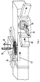
- the object of the present invention as claimed is a new chamber type with polygonal, preferably rectangular cross section based on the application of high acoustic energy levels by means of radiating-stepped-plate type generators (cf. EP-A-450030) which treat an aerosol flow, throughout its passing-by, in direction perpendicular to the propagation ( Figure 1).
- the gases to be treated will flow in a straight line along the chamber axis, indicated by Arrow 1, while the emitters (2), which are of different frequencies, will be distributed on the side walls to create intensive stationary fields which will cover the treatment chamber from end to end in all its different sections without leaving extensive zones at low acoustic levels.
- the chamber walls opposing the emitters will function as reflectors.
- the transducer support implements an adjustment device (3) which permits the variation of the radiator-reflector distance to achieve an optimum stationary field.
- the acoustic emitters to be used in the proposed chamber are of type "plate radiator with stepped profile.”
- the emission from the plate's backside is not taken advantage of for the agglomeration process, except in the case if the mentioned plate is completely introduced in the interior of the treatment chamber.
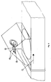
- An arrangement with which the mentioned backside radiation could be realized is presented in Figure 2.
- the transducer (2) is located with its axis parallel to that of the chamber in a way that the radiating plate is situated in between of two reflector plates (5), which form an angle such that the forward as well as the backward radiation can be reflected and normally directed into the gas stream which is flowing along the treatment chamber ( Figure 3).
- This arrangement implies major difficulties on the adjustment and realization of an optimum stationary wave.
- a 20 kHz transducer located with its axis parallel to that of the chamber in between of two plane reflectors which form a 90° angle and are positioned at a 45° angle with respect to the radiating plate, achieves, in a chamber with a cross section of 140 x 60 cm, acoustic pressure levels higher than the 150 dB which are necessary for rapid generation of the acoustic agglomeration phenomenon.
- the mentioned pressure levels are reached with applied powers in the order of 200 W.
- the intensity levels achieved in the interior of the chamber are higher than 160 dB.
- This way one achieves, with frequencies of 20 kHz for aerosols with initial particles from 0,2 to 2 micrometers and concentrations from 0,1 to 4 g/m 3 , enlargement of an order of magnitude. That is to say, the mean size grows from one to ten micrometers. This increase is decisive for the subsequent application of an electrostatic filter to the aerosol flow, since these filters are generally efficient from 5 micrometers on.
Landscapes
- Chemical & Material Sciences (AREA)
- Chemical Kinetics & Catalysis (AREA)
- Organic Chemistry (AREA)
- Health & Medical Sciences (AREA)
- General Health & Medical Sciences (AREA)
- Toxicology (AREA)
- Physical Or Chemical Processes And Apparatus (AREA)
- Processes For Solid Components From Exhaust (AREA)
- Vaporization, Distillation, Condensation, Sublimation, And Cold Traps (AREA)
- Separation By Low-Temperature Treatments (AREA)
Claims (7)
- Akustische Mehrfrequenz-Kammer zum Ansammeln und Abscheiden von Teilchen, die in Abgasen suspendiert sind, wobei die Kammer einen polygonalen Querschnitt aufweist und jede Wand zu einer gegenüberstehenden Wand parallel zu dieser weist, so daß akustische Strahlung, die orthogonal in einer Richtung von einer Wand ausgesandt wird, orthogonal auf eine Oberfläche einer gegenüberstehenden Wand fällt und von der genannten gegenüberstehenden Wand reflektiert wird, was Anlaß zu der Erzeugung eines stationären, akustischen Feldes gibt;die genannte Kammer hat ein Eingangsende und ein Ausgangsende, wobei die Kammerwände einen Strömungsweg in einer Längsrichtung von dem genannten Einlaßende zu dem genannten Auslaßende begrenzen;die Kammer schließt eine Mehrzahl von Schallgebern (2) ein, wobei die genannten Geber an den genannten Wänden an Positionen entlang dem genannten Strömungsweg angeordnet sind, jeder der genannten Schallgeber (2) ausgestaltet ist, Strahlung hoher Intensität bei einer bestimmten Frequenz in einer orthogonalen Richtung in bezug auf die Wand auszusenden, an der der genannte Schallgeber (2) angeordnet ist;die genannten Schallgeber angeordnet sind, unmittelbar von einer Vorderseite einer Strahlerplatte in den genannten Strömungsweg auszusenden;
dadurch gekennzeichnet, daßdie genannten Schallgeber (2) vom abstrahlenden, abgestuften Plattentyp sind; und daßdie Schallgeber (2) so angeordnet sind, daß Strahlung unterschiedlicher Frequenzen an unterschiedlichen Längspositionen entlang dem genannten Strömungsweg ausgesendet werden, um eine angemessene Frequenzverteilung im Hinblick auf die Teilchengrößenverteilung entlang dem genannten länglichen Strömungsweg bereitzustellen. - Akustische Mehrfrequenz-Kammer zum Ansammeln und Abscheiden von Teilchen, die in Abgasen suspendiert sind, wobei die Kammer einen polygonalen Querschnitt aufweist und jede Wand zu einer gegenüberstehenden Wand parallel zu dieser weist, so daß akustische Strahlung, die orthogonal in einer Richtung von einer Wand ausgesandt wird, orthogonal auf eine Oberfläche einer gegenüberstehenden Wand fällt und von der genannten gegenüberstehenden Wand reflektiert wird, was Anlaß zu der Erzeugung eines stationären, akustischen Feldes gibt;die genannte Kammer hat ein Eingangsende und ein Ausgangsende, wobei die Kammerwände einen Strömungsweg in einer Längsrichtung von dem genannten Einlaßende zu dem genannten Auslaßende begrenzen;die Kammer schließt eine Mehrzahl von Schaltgebern (2) ein, wobei die genannten Geber an den genannten Wänden an Positionen entlang dem genannten Strömungsweg angeordnet sind, jeder der genannten Schallgeber (2) ausgestaltet ist, Strahlung hoher Intensität bei einer bestimmten Frequenz in einer orthogonalen Richtung in bezug auf die Wand auszusenden, an der der genannte Schallgeber (2) angeordnet ist;
dadurch gekennzeichnet, daßdie genannten Schallgeber (2) vom abstrahlenden, abgestuften Plattentyp sind; und daßdie Schallgeber (2) angeordnet sind, in den Strömungsweg mittels zweier ebener Reflektoren (5) auszusenden, die an gegenüberstehenden Seiten einer Strahlerplatte des Schallgebers (2) angeordnet sind, um einen Winkel mit der genannten Strahlerplatte derart zu bilden, daß Strahlung von einer Vorderseite und einer Rückseite der genannten Strahlerplatte von den genannten Ebenen Reflektoren reflektiert und in den genannten Strömungsweg in einer orthogonalen Richtung in bezug auf die Wand gelenkt wird, an der der Schallgeber (2) angeordnet ist; und daß die Schallgeber (2) so angeordnet sind, daß die Strahlung unterschiedlicher Frequenzen an unterschiedlichen Längspositionen entlang dem genannten Strömungsweg ausgesandt wird, um eine angemessene Frequenzverteilung im Hinblick auf die Teilchengrößenverteilung entlang demn genannten länglichen Strömungsweg bereitzustellen - Eine akustische Mehrfrequenz-Kammer gemäß Anspruch 1, worin die Schallgeber (2) mit einem Kühlsystem versehen sind, das eine Einrichtung einschließt, um eine laminare Strömung kalter Luft bereitzustellen, die als ein Vorhang dient, der den Schallgeber von heißen Abgasen trennt, die entlang dems Strömungsweg vorbeigehen.
- Eine akustische Mehrfrequenz-Kammer gemäß irgendeinem der vorhergehenden Ansprüche, worin die Schallgeber (2) entlang den Kammerwänden als aneinander angrenzende Einheiten oder Gruppen angeordnet sind.
- Eine akustische Mehrfrequenz-Kammer gemäß irgendeinem der vorhergehenden Ansprüche 1-3, worin die Schallgeber (2) an abwechselnden Wänden angeordnet sind.
- Eine akustische Mehrfrequenz-Kammer gemäß irgendeinem der vorhergehenden Ansprüche, worin die Kammer mit Einstellsystemen (3) zum Einstellen der Position der genannten Strahlerplatten in bezug auf die reflektierenden Oberflächen versehen ist.
- Eine akustische Mehrfrequenz-Kammer gemaß irgendeinem der vorhergehenden Ansprüche, worin der genannte polygonale Querschnitt ein rechteckiger Querschnitt ist.
Applications Claiming Priority (3)
| Application Number | Priority Date | Filing Date | Title |
|---|---|---|---|
| ES9300507 | 1993-03-11 | ||
| ES09300507A ES2067396B1 (es) | 1993-03-11 | 1993-03-11 | Camara acustica multifrecuencia para la aglomeracion y separacion de particulas en suspension en efluentes gaseosos. |
| PCT/ES1994/000026 WO1994020195A1 (es) | 1993-03-11 | 1994-03-11 | Camara acustica multifrecuencia para la aglomeracion y separacion de particulas en suspension en efluentes gaseosos |
Publications (2)
| Publication Number | Publication Date |
|---|---|
| EP0640374A1 EP0640374A1 (de) | 1995-03-01 |
| EP0640374B1 true EP0640374B1 (de) | 1997-11-26 |
Family
ID=8281088
Family Applications (1)
| Application Number | Title | Priority Date | Filing Date |
|---|---|---|---|
| EP94909129A Expired - Lifetime EP0640374B1 (de) | 1993-03-11 | 1994-03-11 | Akustische multifrequenz-kammer zur agglomeration und abscheidung von teilchen aus abgasen |
Country Status (6)
| Country | Link |
|---|---|
| EP (1) | EP0640374B1 (de) |
| AT (1) | ATE160515T1 (de) |
| CA (1) | CA2135759A1 (de) |
| DE (1) | DE69407000T2 (de) |
| ES (1) | ES2067396B1 (de) |
| WO (1) | WO1994020195A1 (de) |
Cited By (1)
| Publication number | Priority date | Publication date | Assignee | Title |
|---|---|---|---|---|
| WO2005002710A1 (en) * | 2003-04-04 | 2005-01-13 | Donaldson Company, Inc. | Acoustical cavity for removal of contaminants from fluid |
Families Citing this family (6)
| Publication number | Priority date | Publication date | Assignee | Title |
|---|---|---|---|---|
| CA2168486C (en) * | 1996-01-31 | 2001-04-17 | Institut Francais Du Petrole | Particle agglomeration and precipitation from a gaseous stream |
| US6776352B2 (en) * | 2001-11-26 | 2004-08-17 | Kimberly-Clark Worldwide, Inc. | Apparatus for controllably focusing ultrasonic acoustical energy within a liquid stream |
| RU2268090C1 (ru) * | 2004-06-15 | 2006-01-20 | Олег Савельевич Кочетов | Акустический циклон |
| KR101745017B1 (ko) | 2011-12-05 | 2017-06-09 | 현대자동차주식회사 | 초음파 고온 진동법을 이용한 열제어 소재용 마이크로 입자와, 이것의 제조 장치 및 방법 |
| CN105251297B (zh) * | 2015-09-28 | 2017-06-09 | 东南大学 | 一种环形声场迁移悬浮颗粒的装置及用于该装置的方法 |
| CN105289171A (zh) * | 2015-10-28 | 2016-02-03 | 东南大学 | 一种环形声场迁移悬浮颗粒的装置及用于该装置的方法 |
Family Cites Families (9)
| Publication number | Priority date | Publication date | Assignee | Title |
|---|---|---|---|---|
| US3771286A (en) * | 1972-02-04 | 1973-11-13 | Chubb Ind Ltd | Method of coagulating aerosols |
| US3976448A (en) * | 1972-04-20 | 1976-08-24 | Lin Eng Corporation | Electrostatic and sonic gas processing apparatus |
| DE2304597A1 (de) * | 1973-01-31 | 1974-08-08 | Sabahattin Algan | Verfahren zur abscheidung von feststoffpartikeln aus gasen und anordnung zur durchfuehrung des verfahrens |
| US4339247A (en) * | 1981-04-27 | 1982-07-13 | Battelle Development Corporation | Acoustic degasification of pressurized liquids |
| US4378976A (en) * | 1981-08-14 | 1983-04-05 | Institute Of Gas Technology | Combined sonic agglomerator/cross flow filtration apparatus and process for solid particle and/or liquid droplet removal from gas streams |
| US4475921A (en) * | 1982-03-24 | 1984-10-09 | The United States Of America As Represented By The Administrator Of The National Aeronautics And Space Administration | Acoustic agglomeration methods and apparatus |
| EP0450030B1 (de) * | 1989-10-06 | 1994-07-27 | Consejo Superior De Investigaciones Cientificas | Elektroakustische einheit zur erregung von hochintensitätsschall und -ultraschall in gasen und zwischenphasen |
| US5085783A (en) * | 1990-08-16 | 1992-02-04 | Case Western Reserve University | Acoustically driven particle separation method and apparatus |
| LU87850A1 (de) * | 1990-11-27 | 1992-08-25 | Euratom | Akustische kammer fuer die aerosolbehandlung von abgasen |
-
1993
- 1993-03-11 ES ES09300507A patent/ES2067396B1/es not_active Expired - Fee Related
-
1994
- 1994-03-11 CA CA002135759A patent/CA2135759A1/en not_active Abandoned
- 1994-03-11 WO PCT/ES1994/000026 patent/WO1994020195A1/es not_active Ceased
- 1994-03-11 DE DE69407000T patent/DE69407000T2/de not_active Expired - Fee Related
- 1994-03-11 EP EP94909129A patent/EP0640374B1/de not_active Expired - Lifetime
- 1994-03-11 AT AT94909129T patent/ATE160515T1/de not_active IP Right Cessation
Cited By (1)
| Publication number | Priority date | Publication date | Assignee | Title |
|---|---|---|---|---|
| WO2005002710A1 (en) * | 2003-04-04 | 2005-01-13 | Donaldson Company, Inc. | Acoustical cavity for removal of contaminants from fluid |
Also Published As
| Publication number | Publication date |
|---|---|
| ATE160515T1 (de) | 1997-12-15 |
| EP0640374A1 (de) | 1995-03-01 |
| DE69407000D1 (de) | 1998-01-08 |
| ES2067396B1 (es) | 1997-11-01 |
| ES2067396R (de) | 1997-04-01 |
| ES2067396A2 (es) | 1995-03-16 |
| WO1994020195A1 (es) | 1994-09-15 |
| CA2135759A1 (en) | 1994-09-12 |
| DE69407000T2 (de) | 1998-04-16 |
Similar Documents
| Publication | Publication Date | Title |
|---|---|---|
| US5769913A (en) | Multifrequency acoustic chamber for the agglomeration and separation of particles suspended in gaseous effluents | |
| US4475921A (en) | Acoustic agglomeration methods and apparatus | |
| EP0640374B1 (de) | Akustische multifrequenz-kammer zur agglomeration und abscheidung von teilchen aus abgasen | |
| WO1992009354A1 (en) | An acoustic chamber for the aerosol treatment of exhaust gases | |
| RU2447926C2 (ru) | Способ коагуляции инородных частиц в газовых потоках | |
| WO2014082125A1 (en) | System and method for particulate matter agglomeration | |
| WO2013142289A1 (en) | Air purification system | |
| Reethof | Acoustic agglomeration of power plant fly ash for environmental and hot gas clean-up | |
| US4858717A (en) | Acoustic convective system | |
| KR20030057582A (ko) | 초음파를 이용한 유해 배기가스 및 매연 집진장치 | |
| GB2546792A (en) | A silencer | |
| Lee et al. | Acoustic levitating apparatus for submillimeter samples | |
| Khmelev et al. | Experimental stand for the research of the process of ultrasonic coagulation of aerosols | |
| RU102197U1 (ru) | Ультразвуковая коагуляционная камера | |
| JP3471548B2 (ja) | 浮遊粒子の収集方法とその装置 | |
| Gallego-Juarez | New technologies in high-power ultrasonic industrial applications | |
| Khmelev et al. | Experimental study of aerosol coagulation during the formation of vortex flows in a heterogeneous ultrasonic field | |
| Khmelev et al. | Ultrasonic coagulation on the basis of piezoelectric vibrating system with focusing radiator in the form of step-variable plate | |
| EP0838635A2 (de) | Vorrichtung zur Reduzierung der Geräuschentwicklung bei einem Verbrennungsheizapparat | |
| Dorovskikh et al. | Development of specialized disk emitters for the formation of high-intensity ultrasonic fields in gaseous media | |
| Доровских et al. | Effect of high-intensity ultrasonic field on fog droplet coagulation efficiency | |
| EP4509202A1 (de) | Vorrichtung zur akustischen agglomeration von ultrafeinen feststoffteilchen | |
| RU2759506C1 (ru) | Способ ультразвуковой коагуляции | |
| RU2079345C1 (ru) | Способ удаления инородных частиц из текучей среды и устройство для его осуществления | |
| Khmelev et al. | Increasing the Efficiency of Ultrasonic Agglomeration Due to Acoustic Streams |
Legal Events
| Date | Code | Title | Description |
|---|---|---|---|
| PUAI | Public reference made under article 153(3) epc to a published international application that has entered the european phase |
Free format text: ORIGINAL CODE: 0009012 |
|
| 17P | Request for examination filed |
Effective date: 19941122 |
|
| AK | Designated contracting states |
Kind code of ref document: A1 Designated state(s): AT BE CH DE DK ES FR GB GR IE IT LI LU MC NL PT SE |
|
| 17Q | First examination report despatched |
Effective date: 19951206 |
|
| GRAG | Despatch of communication of intention to grant |
Free format text: ORIGINAL CODE: EPIDOS AGRA |
|
| GRAH | Despatch of communication of intention to grant a patent |
Free format text: ORIGINAL CODE: EPIDOS IGRA |
|
| GRAH | Despatch of communication of intention to grant a patent |
Free format text: ORIGINAL CODE: EPIDOS IGRA |
|
| GRAA | (expected) grant |
Free format text: ORIGINAL CODE: 0009210 |
|
| AK | Designated contracting states |
Kind code of ref document: B1 Designated state(s): AT BE CH DE DK ES FR GB GR IE IT LI LU MC NL PT SE |
|
| PG25 | Lapsed in a contracting state [announced via postgrant information from national office to epo] |
Ref country code: NL Free format text: LAPSE BECAUSE OF FAILURE TO SUBMIT A TRANSLATION OF THE DESCRIPTION OR TO PAY THE FEE WITHIN THE PRESCRIBED TIME-LIMIT Effective date: 19971126 Ref country code: LI Free format text: LAPSE BECAUSE OF FAILURE TO SUBMIT A TRANSLATION OF THE DESCRIPTION OR TO PAY THE FEE WITHIN THE PRESCRIBED TIME-LIMIT Effective date: 19971126 Ref country code: GR Free format text: LAPSE BECAUSE OF FAILURE TO SUBMIT A TRANSLATION OF THE DESCRIPTION OR TO PAY THE FEE WITHIN THE PRESCRIBED TIME-LIMIT Effective date: 19971126 Ref country code: ES Free format text: THE PATENT HAS BEEN ANNULLED BY A DECISION OF A NATIONAL AUTHORITY Effective date: 19971126 Ref country code: DK Free format text: LAPSE BECAUSE OF NON-PAYMENT OF DUE FEES Effective date: 19971126 Ref country code: CH Free format text: LAPSE BECAUSE OF FAILURE TO SUBMIT A TRANSLATION OF THE DESCRIPTION OR TO PAY THE FEE WITHIN THE PRESCRIBED TIME-LIMIT Effective date: 19971126 Ref country code: BE Free format text: LAPSE BECAUSE OF FAILURE TO SUBMIT A TRANSLATION OF THE DESCRIPTION OR TO PAY THE FEE WITHIN THE PRESCRIBED TIME-LIMIT Effective date: 19971126 Ref country code: AT Free format text: LAPSE BECAUSE OF FAILURE TO SUBMIT A TRANSLATION OF THE DESCRIPTION OR TO PAY THE FEE WITHIN THE PRESCRIBED TIME-LIMIT Effective date: 19971126 |
|
| REF | Corresponds to: |
Ref document number: 160515 Country of ref document: AT Date of ref document: 19971215 Kind code of ref document: T |
|
| REG | Reference to a national code |
Ref country code: CH Ref legal event code: EP |
|
| ITF | It: translation for a ep patent filed | ||
| REF | Corresponds to: |
Ref document number: 69407000 Country of ref document: DE Date of ref document: 19980108 |
|
| PG25 | Lapsed in a contracting state [announced via postgrant information from national office to epo] |
Ref country code: SE Free format text: LAPSE BECAUSE OF FAILURE TO SUBMIT A TRANSLATION OF THE DESCRIPTION OR TO PAY THE FEE WITHIN THE PRESCRIBED TIME-LIMIT Effective date: 19980226 Ref country code: PT Free format text: LAPSE BECAUSE OF FAILURE TO SUBMIT A TRANSLATION OF THE DESCRIPTION OR TO PAY THE FEE WITHIN THE PRESCRIBED TIME-LIMIT Effective date: 19980226 |
|
| ET | Fr: translation filed | ||
| PG25 | Lapsed in a contracting state [announced via postgrant information from national office to epo] |
Ref country code: LU Free format text: LAPSE BECAUSE OF NON-PAYMENT OF DUE FEES Effective date: 19980311 Ref country code: IE Free format text: LAPSE BECAUSE OF NON-PAYMENT OF DUE FEES Effective date: 19980311 |
|
| NLV1 | Nl: lapsed or annulled due to failure to fulfill the requirements of art. 29p and 29m of the patents act | ||
| REG | Reference to a national code |
Ref country code: CH Ref legal event code: PL |
|
| PG25 | Lapsed in a contracting state [announced via postgrant information from national office to epo] |
Ref country code: MC Free format text: LAPSE BECAUSE OF NON-PAYMENT OF DUE FEES Effective date: 19980930 |
|
| PLBE | No opposition filed within time limit |
Free format text: ORIGINAL CODE: 0009261 |
|
| STAA | Information on the status of an ep patent application or granted ep patent |
Free format text: STATUS: NO OPPOSITION FILED WITHIN TIME LIMIT |
|
| 26N | No opposition filed | ||
| REG | Reference to a national code |
Ref country code: GB Ref legal event code: IF02 |
|
| PGFP | Annual fee paid to national office [announced via postgrant information from national office to epo] |
Ref country code: GB Payment date: 20040310 Year of fee payment: 11 Ref country code: FR Payment date: 20040310 Year of fee payment: 11 |
|
| PGFP | Annual fee paid to national office [announced via postgrant information from national office to epo] |
Ref country code: DE Payment date: 20040430 Year of fee payment: 11 |
|
| PG25 | Lapsed in a contracting state [announced via postgrant information from national office to epo] |
Ref country code: IT Free format text: LAPSE BECAUSE OF NON-PAYMENT OF DUE FEES Effective date: 20050311 Ref country code: GB Free format text: LAPSE BECAUSE OF NON-PAYMENT OF DUE FEES Effective date: 20050311 |
|
| PG25 | Lapsed in a contracting state [announced via postgrant information from national office to epo] |
Ref country code: DE Free format text: LAPSE BECAUSE OF NON-PAYMENT OF DUE FEES Effective date: 20051001 |
|
| GBPC | Gb: european patent ceased through non-payment of renewal fee |
Effective date: 20050311 |
|
| PG25 | Lapsed in a contracting state [announced via postgrant information from national office to epo] |
Ref country code: FR Free format text: LAPSE BECAUSE OF NON-PAYMENT OF DUE FEES Effective date: 20051130 |
|
| REG | Reference to a national code |
Ref country code: FR Ref legal event code: ST Effective date: 20051130 |