EP0640234B1 - Münzbetätigtes schloss - Google Patents
Münzbetätigtes schloss Download PDFInfo
- Publication number
- EP0640234B1 EP0640234B1 EP93909809A EP93909809A EP0640234B1 EP 0640234 B1 EP0640234 B1 EP 0640234B1 EP 93909809 A EP93909809 A EP 93909809A EP 93909809 A EP93909809 A EP 93909809A EP 0640234 B1 EP0640234 B1 EP 0640234B1
- Authority
- EP
- European Patent Office
- Prior art keywords
- coin
- key
- release member
- opening
- slide
- Prior art date
- Legal status (The legal status is an assumption and is not a legal conclusion. Google has not performed a legal analysis and makes no representation as to the accuracy of the status listed.)
- Expired - Lifetime
Links
- 238000003780 insertion Methods 0.000 claims abstract description 26
- 230000037431 insertion Effects 0.000 claims abstract description 8
- 230000000717 retained effect Effects 0.000 claims description 13
- 230000000295 complement effect Effects 0.000 claims description 2
- 230000000694 effects Effects 0.000 description 2
- 230000000881 depressing effect Effects 0.000 description 1
- 230000001747 exhibiting effect Effects 0.000 description 1
Images
Classifications
-
- G—PHYSICS
- G07—CHECKING-DEVICES
- G07F—COIN-FREED OR LIKE APPARATUS
- G07F7/00—Mechanisms actuated by objects other than coins to free or to actuate vending, hiring, coin or paper currency dispensing or refunding apparatus
- G07F7/06—Mechanisms actuated by objects other than coins to free or to actuate vending, hiring, coin or paper currency dispensing or refunding apparatus by returnable containers, i.e. reverse vending systems in which a user is rewarded for returning a container that serves as a token of value, e.g. bottles
- G07F7/0618—Mechanisms actuated by objects other than coins to free or to actuate vending, hiring, coin or paper currency dispensing or refunding apparatus by returnable containers, i.e. reverse vending systems in which a user is rewarded for returning a container that serves as a token of value, e.g. bottles by carts
- G07F7/0654—Mechanisms actuated by objects other than coins to free or to actuate vending, hiring, coin or paper currency dispensing or refunding apparatus by returnable containers, i.e. reverse vending systems in which a user is rewarded for returning a container that serves as a token of value, e.g. bottles by carts in which the lock functions according to a "pinching of the token" principle, i.e. the token is held between two members
-
- Y—GENERAL TAGGING OF NEW TECHNOLOGICAL DEVELOPMENTS; GENERAL TAGGING OF CROSS-SECTIONAL TECHNOLOGIES SPANNING OVER SEVERAL SECTIONS OF THE IPC; TECHNICAL SUBJECTS COVERED BY FORMER USPC CROSS-REFERENCE ART COLLECTIONS [XRACs] AND DIGESTS
- Y10—TECHNICAL SUBJECTS COVERED BY FORMER USPC
- Y10S—TECHNICAL SUBJECTS COVERED BY FORMER USPC CROSS-REFERENCE ART COLLECTIONS [XRACs] AND DIGESTS
- Y10S194/00—Check-actuated control mechanisms
- Y10S194/905—Shopping cart return
Definitions
- the present invention relates to a coin-deposit lock, said lock being adapted to be placed on a trolley and being of the kind set forth in the preamble of claim 1.
- Coin-deposit locks of this kind are e.g. disclosed in the DK Published Applications Nos. 145,550 and 145,952, and the International Application No. WO82/01950 being included herein by reference. These coin-deposit locks suffer from the disadvantage that they are not especially selective with regard to the size and hence the value of the coin having been inserted, for which reason they are less suitable for achieving the purpose of such coin-deposit locks, viz. to ensure that the trolley is returned and connected to the row of trolleys, to which it belongs, so that the amount deposited is returned.
- the coin having been inserted has a larger diameter than the correct coin (provided that it is at all possible to insert the coin in the coin-insertion opening) or a smaller diameter than the correct coin, then the first latching member on the release member cannot engage in the through-going apertures in the main slide and the measuring slide, and the release member cannot pivot towards its first position and release the second key belonging to a preceding trolley in the row from the second key opening so as to liberate the trolley from the row of trolleys. Then, the wrong coin having been inserted will simply be returned to the coin-insertion opening when the first key is again removed from the first key opening. Solely when a coin of the correct size is inserted into the coin-insertion opening, the second key will be freed from the coin-deposit lock and the first key will be retained in the lock.
- This known coin-deposit lock which incidentally in the embodiment shown and described is adapted to accept coins of two different sizes, suffers from the conspicuous disadvantage that the key chained to the lock itself or to the trolley, to which it is secured, has to be chained with a chain, that is too short to allow this key itself to be introduced in the key opening of the lock to free the coin having been inserted. In this case, the effect to be achieved with the lock would, of course, be lost, since a user of the trolley could free the deposited coin as she or he pleases and without the trolley having been returned to the row of trolleys and chained to a preceding trolley.
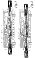
- the coin-deposit lock comprises a housing consisting of two housing parts, viz. an upper housing part 2 and a lower housing part 4.
- the housing is provided with a first keyhole 6 for receiving a first key 8 associated with the coin-deposit lock
- the housing is provided with a second keyhole 10 for receiving a second key 12, connected by a chain to a corresponding coin-deposit lock on a preceding trolley in a row of trolleys.
- a main slide 14, preferably situated in the upper housing part 2 is slidable in the longitudinal direction of the housing and biased towards the right in the Figures by a spring 16.
- the main slide 14 has a downwardly protruding part 18 adapted to abut against the front edge of the first key 8. Situated above the main slide 14 and likewise slidable in the longitudinal direction of the housing there is a measuring slide 20, biased towards the right in the Figures by a spring 22, of which - for the sake of clearness - only a part is shown in the Figures.
- the measuring slide 20 comprises a centrally situated aperture 24, elongated in the transverse direction, and the main slide 14 comprises a corresponding aperture 26.
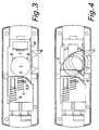
- These apertures 24 and 26 are placed in such a manner in the measuring slide and the main slide 20 and 14, respectively, that when a coin C of the correct value, i.e. with the correct diameter, is placed between stops 28 and 30 (see Figure 3) on the slides 14 and 20, the apertures will be in mutual alignment as shown in Figures 1, 2, and 3.
- a release member 34 adapted to pivot between a first position shown in Figure 2 and a second position shown in Figure 1.
- the release member 34 comprises a first latching finger 36, in the first position of the release member 34 shown in Figure 2 engaging with the mutually aligned apertures 24 and 26 in the measuring and main slides 20 and 14, respectively, and retaining the latter, having been moved forward with the coin C lying between them to the withdrawn position shown in Figure 2 by the first key 8.
- the second key 12 associated with a preceding trolley in the row of trolleys is also freed, i.e. the trolley may be removed from the row of trolleys, the coin C being retained inside the coin-deposit lock.
- the first latching finger 36 has been disengaged from the mutually aligned apertures 24 and 26 in the slides 20 and 14, and the latter have, together with the coin C, been moved back to the starting position by the springs 22 and 16, in which position the coin C may be removed from the coin-insertion opening in the coin-deposit lock.
- first ejector 46 and a second ejector 48 slidable in the longitudinal direction of the housing and biased away from each other by springs 50, of which only one is shown in the drawing.
- the key 8 When the first key 8 is inserted in the first keyhole 6, the key 8 will move the first ejector 46 forward from the position shown in Figure 1 to the position shown in Figure 2, in which the first ejector 46 is retained by a fourth latching finger 52 on the release member 34, the finger 52 engaging in a recess 54 in the first ejector 46.
- a fifth latching finger 56 on the release member 34 has been disengaged from a recess 58 in the second ejector 48, the latter under the influence of the force from the springs 50 having been moved towards the left in the Figure so as to eject the second key 12 from the second keyhole 10.
- this mechanism consists of a small slide 60 capable of limited movement together with the ejectors 46 and 48 and being biased away from the ejector 46 by a spring 62.
- the slide 60 is provided with a central opening, through which protrudes a pin 64, secured to the release member 34 opposite the latter's pivoting axis 32.
- Movement of the ejectors 46 and 48 in the manner described above results in a corresponding but limited movement of the small slide 60, and hence a pivoting movement of the pin 64 and with it the release member 34 from the first position shown in Figure 2 to the second position shown in Figure 1, and vice versa.
- Figure 3 shows the coin-deposit lock seen from above in a situation, in which the coin C has been removed from the coin-insertion opening 66 by stops 28 on the main slide 14 and moved forward so as to abut against a stop 30 on the measuring slide 20, so that the apertures 24 and 26 in the slides are mutually aligned.
- Figure 4 shows diagrammatically how the stop 30 on the measuring slide 20 in connection with a further, oblique stop 70 on this slide together with a curved guide track 72 in the upper housing part 2 and under the influence of the force from the spring 22 will move the coin C from the position shown in Figure 3 out into the coin-insertion opening 66, from which it may be removed by the user of the trolley.
- all the keys 8 and 12 in a group of locks associated with trolleys belonging to the same set have a particular axial-symmetrical shape, at least on the part to be inserted in the keyholes 6 and 10, said shape e.g. comprising protrusions and/or recesses extending parallel to the axis of this part, each of the keyholes 6 and 10 having an axial-symmetrical shape complementary to the shape of the keys.
Landscapes
- Physics & Mathematics (AREA)
- General Physics & Mathematics (AREA)
- Testing Of Coins (AREA)
- Coin-Freed Apparatuses For Hiring Articles (AREA)
- Lock And Its Accessories (AREA)
- Professional, Industrial, Or Sporting Protective Garments (AREA)
- Handcart (AREA)
- Noodles (AREA)
- Purses, Travelling Bags, Baskets, Or Suitcases (AREA)
- Detergent Compositions (AREA)
- Control Of Vending Devices And Auxiliary Devices For Vending Devices (AREA)
Claims (9)
- Münzpfandschloss zur Anbringung auf einem Wagen, der Teil einer Reihe aus solchen miteinander verbundenen Wagen sein kann, wobei die genannten Wagen insbesondere in Gestalt von Einkaufs- und Gepäckwagen sind, das genannte Münzpfandschloss ist so eingerichtet, dass es einen mit der Reihe verbundenen Wagen durch Einführen einer Münze eines bestimmten Wertes in das Schloss freigibt und die eingeführte Münze auswirft, wenn der Wagen an seinen Platz zurückgeführt und wieder mit der Reihe verbunden wird, das genannte Münzpfandschloss ist von der Art, das umfasst eine Münzeinführungsöffnung (66), ein drehbares Freigabeorgan (34) und zwei Schlüsselöffnungen, die blockiert werden können, nämlich eine erste Schlüsselöffnung (6) zur Aufnahme und zum Festhalten eines ersten, zum Münzpfandschloss gehörenden Schlüssels (8) und eine zweite Schlüsselöffnung (10) zur Aufnahme und zum Festhalten eines zweiten, zu einem entsprechenden Münzpfandschloss auf einem vorhergehenden Wagen in der Reihe gehörenden Schlüssels (12), gekennzeichnet durch die Kombination von Abtastmitteln für die Münzgrösse, die einen federbeeinflussten Hauptschlitten (14) und einen federbeeinflussten Messchlitten (20) umfassen, und dem drehbaren Freigabeorgan (34), in dem das Einführen einer korrekten Münze (C) in die Münzeinführungsöffnung (66) und anschliessendes Einführen des ersten Schlüssels (8) in die erste Schlüsselöffnung (6) bewirkt, dass die Münze (C), der Hauptschlitten (14) und der Messchlitten (20) nach vorn in eine festgehaltene Position in dem Schloss bewegt werden und das Freigabeorgan (34) in eine erste Position (Figur 2) gedreht wird, in der ein erstes Einklinkorgan (36) auf dem Freigabeorgan (34) in Eingriff kommt mit einer durchgehenden Öffnung (24,26) in dem Hauptschlitten (14) und dem Messchlitten (20) und diese Schlitten festhält, und ein zweites Einklinkorgan (38) auf dem Freigabeorgan (34) aus einer Öffnung (40) in dem zweiten Schlüssel (12) ausgeklinkt wird und letzteren aus der zweiten Schlüsselöffnung (10) freigibt, und wo das Wiedereinführen des zweiten Schlüssels (12) in die zweite Schlüsselöffnung (10) das Drehen des Freigabeorgans (34) in eine zweite Position (Figur 1) bewirkt, in der das erste Einklinkorgan (36) den Hauptschlitten (14) und den Messchlitten (20) freigibt, und die Münze (C) an die Münzeinführungsöffnung (66) zurückgeführt wird, und in der das zweite Einklinkorgan (38) in Eingriff kommt mit der Öffnung (40) in dem zweiten Schlüssel (12) und letzteren in der zweiten Schlüsselöffnung (10) festhält, und in der das Freigabeorgan (34) ein drittes Einklinkorgan (42) hat, das in der ersten Position (Figur 2) des Freigabeorgans (34) in Eingriff kommt mit einer Öffnung (44) in dem ersten Schlüssel (8) und letzteren in der ersten Schlüsselöffnung (6) festhält, und in der zweiten Position (Figur 1) des Freigabeorgans (34) aus der Öffnung (44) in dem ersten Schlüssel (8) ausgeklinkt wird und letzteren aus der ersten Schlüsselöffnung (6) freigibt.
- Münzpfandschloss gemäss Anspruch 1, gekennzeichnet durch den Hauptschlitten (14) und den Messchlitten (20) mit je einer Öffnung (24,26), die genannten Öffnungen werden, wenn eine Münze (C) des genannten bestimmten Wertes zwischen die Schlitten (14,20) eingeführt worden ist, gegenseitig ausgerichtet und in die Lage versetzt, in Eingriff zu kommen mit dem ersten Einklinkorgan (36) auf dem Freigabeorgan (34).
- Münzpfandschloss gemäss Anspruch 1 oder 2, dadurch gekennzeichnet, dass es weiterhin umfasst einen ersten (46) und einen zweiten (48) Auswerfer, die genannten Auswerfer voneinander weg federbeeinflusst werden durch Auswerffedern (50), wo der erste Auswerfer (46) durch Einführen des ersten Schlüssels (8) in die erste Schlüsselöffnung (6) zu dem zweiten Auswerfer (48) hin bewegt und von einem vierten Einklinkorgan (52) auf dem Freigabeorgan (34) in der ersten Position (Figur 2) des letzteren festgehalten wird, während gleichzeitig ein fünftes Einklinkorgan (56) auf dem Freigabeorgan (34) den zweiten Auswerfer (48) freigibt, sodass letzterer den zweiten Schlüssel (12) aus der zweiten Schlüsselöffnung (10) bewegt, und wo der zweite Auswerfer (48) nach Einführen des zweiten Schlüssels (12) in die zweite Schlüsselöffnung (10) auf den ersten Auswerfer (46) zu bewegt und von dem fünften Einklinkorgan (56) auf dem Freigabeorgan (34) in der zweiten Position (Figur 1) des letzteren festgehalten wird, während der erste Auswerfer (46) von dem vierten Einklinkorgan (52) auf dem Freigabeorgan (34) freigegeben wird, sodass er den ersten Schlüssel (8) aus der ersten Schlüsselöffnung (6) bewegt.
- Münzpfandschloss gemäss Anspruch 3, gekennzeichnet durch einen zwischen dem ersten (46) und dem zweiten (48) Auswerfer angebrachten Schlitten (60), der zur begrenzten Bewegung zusammen mit einem jeden Auswerfer eingerichtet ist und von dem ersten Auswerfer (46) weg federbeeinflusst (62) wird, genannter Schlitten (60) wird in Eingriff gebracht mit einem Zapfen (64) auf dem drehbaren Freigabeorgan (34), um letzteren aus seiner ersten Position (Figur 2) in seine zweite Position (Figur 1) und umgekehrt zu schalten.
- Münzpfandschloss gemäss einem jeden oder einem beliebigen der Ansprüche 1-4, dadurch gekennzeichnet, dass der Hauptschlitten (14) mit Arretierungen (28) versehen ist, die nach Vorwärtsbewegung des Hauptschlittens (14), wenn der erste Schlüssel (8) in die erste Schlüsselöffnung (6) eingeführt ist, die Münze (C) nach vorn von der Münzeinführungsöffnung (66) zu einer Position zwischen der genannten Arretierung (28) und einer Arretierung (30) auf dem Messschlitten (20) bewegen.
- Münzpfandschloss gemäss einem jeden oder einem beliebigen der Ansprüche 1-5 und von der Art, die umfasst ein Gehäuse mit einem oberen Gehäuseteil (2) und einem unteren Gehäuseteil (4), dadurch gekennzeichnet, dass der obere Gehäuseteil (2) eine Führungsspur (72) aufweist, die so eingerichtet ist, dass sie beim Rücklauf des Hauptschlittens (14) und des Messchlittens (20) und der dazwischenliegenden Münze (C) aus der in dem Schloss festgehaltenen Position die Münze auf die Münzeinführungsöffnung (66) zu bewegt.
- Münzpfandschloss gemäss einem jeden oder einem beliebigen der Ansprüche 1-6, dadurch gekennzeichnet, dass der Hauptschlitten (14) ein nach oben vorstehendes Randorgan (68) hat, das dazu eingerichtet ist, die Münzeinführungsöffnung (66) in der nach vorn bewegten und festgehaltenen Position des Schlittens im Schloss zu blockieren.
- Münzpfandschloss gemäss einem jedem oder einem beliebigen der Ansprüche 1-7, dadurch gekennzeichnet, dass alle Schlüssel in einem System von Schlössern, die mit einer Reihe von zu dem gleichen Satz gehörenden Wagen verbunden sind, zumindest an dem Teil, der zur Einführung in die Schlüsselöffnung eingerichtet ist, eine besondere achsialsymmetrische Form haben, die sich parallel zur Achse der Schlüssel erstreckt, und dass alle Schlüsselöffnungen in den zu genannten Systemen gehörenden Münzpfandschlössern eine komplementäre Form haben.
- Münzpfandschloss gemäss einem jeden oder einem beliebigen der Ansprüche 1-8, dadurch gekennzeichnet, dass die erste Schlüsselöffnung (6) so eingerichtet ist, dass sie verhindert, dass Fremdkörper, insbesondere Münzen, hierin festgeklemmt oder verkeilt werden.
Applications Claiming Priority (3)
| Application Number | Priority Date | Filing Date | Title |
|---|---|---|---|
| DK573/92 | 1992-05-01 | ||
| DK057392A DK169005B1 (da) | 1992-05-01 | 1992-05-01 | Møntlåsautomat |
| PCT/DK1993/000141 WO1993022750A1 (en) | 1992-05-01 | 1993-04-28 | Coin-deposit lock |
Publications (2)
| Publication Number | Publication Date |
|---|---|
| EP0640234A1 EP0640234A1 (de) | 1995-03-01 |
| EP0640234B1 true EP0640234B1 (de) | 1996-02-21 |
Family
ID=8095085
Family Applications (1)
| Application Number | Title | Priority Date | Filing Date |
|---|---|---|---|
| EP93909809A Expired - Lifetime EP0640234B1 (de) | 1992-05-01 | 1993-04-28 | Münzbetätigtes schloss |
Country Status (11)
| Country | Link |
|---|---|
| US (1) | US5495930A (de) |
| EP (1) | EP0640234B1 (de) |
| JP (1) | JPH07506203A (de) |
| AT (1) | ATE134452T1 (de) |
| AU (1) | AU669523B2 (de) |
| CA (1) | CA2118137A1 (de) |
| CZ (1) | CZ262394A3 (de) |
| DE (1) | DE69301601D1 (de) |
| DK (1) | DK169005B1 (de) |
| ES (1) | ES2085776T3 (de) |
| WO (1) | WO1993022750A1 (de) |
Families Citing this family (3)
| Publication number | Priority date | Publication date | Assignee | Title |
|---|---|---|---|---|
| DE4341791A1 (de) * | 1993-06-04 | 1994-12-08 | Vendoret Holding Sa | Karte für ein Pfandschloß |
| DE19600248C1 (de) * | 1996-01-05 | 1997-07-31 | Boehringer Rainer | Pfandschloß |
| FR2810771A1 (fr) * | 2000-06-21 | 2001-12-28 | Gerard Rumont | Dispositif de verrouillage actionnable a l'aide d'une cle moyennant l'insertion d'une piece de monnaie dans un logement |
Citations (3)
| Publication number | Priority date | Publication date | Assignee | Title |
|---|---|---|---|---|
| US2818956A (en) * | 1953-03-23 | 1958-01-07 | Mclaney Mfg Corp | Coin controlled lock |
| US3966033A (en) * | 1975-02-20 | 1976-06-29 | Duncan Doo | Coin-check operated article lock |
| DE3242045A1 (de) * | 1982-11-13 | 1984-05-17 | Schulte-Schlagbaum Ag, 5620 Velbert | Schloss, insbesondere pfandschloss |
Family Cites Families (3)
| Publication number | Priority date | Publication date | Assignee | Title |
|---|---|---|---|---|
| DK145952C (da) * | 1980-11-28 | 1983-09-19 | Catena Locks As | Moentlaasautomat til anbringelse paa vogne, isaer indkoebsvogne og bagagevogne |
| DK145550C (da) * | 1980-11-28 | 1983-05-09 | Catena Locks As | Moentlaasautomat til et anlaeg med vogne,isaer indkoebsvogne og bagagevogne |
| DK163387C (da) * | 1988-12-20 | 1992-07-13 | Catena Systems Aps | Moentlaasautomat til udlevering af et i automaten fastholdt laaseorgan |
-
1992
- 1992-05-01 DK DK057392A patent/DK169005B1/da not_active IP Right Cessation
-
1993
- 1993-04-28 JP JP5518850A patent/JPH07506203A/ja active Pending
- 1993-04-28 AT AT93909809T patent/ATE134452T1/de not_active IP Right Cessation
- 1993-04-28 AU AU40601/93A patent/AU669523B2/en not_active Ceased
- 1993-04-28 DE DE69301601T patent/DE69301601D1/de not_active Expired - Lifetime
- 1993-04-28 CA CA002118137A patent/CA2118137A1/en not_active Abandoned
- 1993-04-28 WO PCT/DK1993/000141 patent/WO1993022750A1/en not_active Ceased
- 1993-04-28 CZ CZ942623A patent/CZ262394A3/cs unknown
- 1993-04-28 ES ES93909809T patent/ES2085776T3/es not_active Expired - Lifetime
- 1993-04-28 EP EP93909809A patent/EP0640234B1/de not_active Expired - Lifetime
- 1993-04-28 US US08/318,827 patent/US5495930A/en not_active Expired - Fee Related
Patent Citations (3)
| Publication number | Priority date | Publication date | Assignee | Title |
|---|---|---|---|---|
| US2818956A (en) * | 1953-03-23 | 1958-01-07 | Mclaney Mfg Corp | Coin controlled lock |
| US3966033A (en) * | 1975-02-20 | 1976-06-29 | Duncan Doo | Coin-check operated article lock |
| DE3242045A1 (de) * | 1982-11-13 | 1984-05-17 | Schulte-Schlagbaum Ag, 5620 Velbert | Schloss, insbesondere pfandschloss |
Also Published As
| Publication number | Publication date |
|---|---|
| DK169005B1 (da) | 1994-07-25 |
| DK57392D0 (da) | 1992-05-01 |
| AU669523B2 (en) | 1996-06-13 |
| DK57392A (da) | 1993-11-02 |
| AU4060193A (en) | 1993-11-29 |
| WO1993022750A1 (en) | 1993-11-11 |
| DE69301601D1 (de) | 1996-03-28 |
| CA2118137A1 (en) | 1993-11-11 |
| JPH07506203A (ja) | 1995-07-06 |
| US5495930A (en) | 1996-03-05 |
| ATE134452T1 (de) | 1996-03-15 |
| CZ262394A3 (en) | 1995-02-15 |
| ES2085776T3 (es) | 1996-06-01 |
| EP0640234A1 (de) | 1995-03-01 |
Similar Documents
| Publication | Publication Date | Title |
|---|---|---|
| AU626179B2 (en) | A coin lock for a trolley | |
| US4941560A (en) | Security device for trolleys | |
| US5560232A (en) | Combination lock having a shackle | |
| SE430186B (sv) | Myntmanovrerat las | |
| US5495930A (en) | Coin-deposit lock | |
| US4637507A (en) | Coin lock device for shopping trolleys | |
| WO1984004835A1 (en) | Releasable coupling device | |
| CN101510642A (zh) | 用于与安全入口连接的装置 | |
| US5540316A (en) | Coin controlled apparatus for locking shopping carts together | |
| US20080106050A1 (en) | Push Cart With Coupling Device | |
| US8013246B2 (en) | Push-in emergency stop cover with plug-in unit | |
| US5220987A (en) | Coin-controlled apparatus for locking shopping carts together | |
| AU597417B2 (en) | Security device for trolleys | |
| GB2263353A (en) | Security device for shopping trolleys avoiding jamming by over or under sized coins | |
| WO1991006930A1 (en) | Coin-freed shopping trolley lock | |
| IE910510A1 (en) | Transport trolley with coin lock | |
| CA2086319C (en) | Device for confining rows of shopping carts | |
| WO1998038604A1 (en) | Device for a cash register | |
| EP0551213A2 (de) | Münzschloss | |
| CN223374214U (zh) | 一种宠物笼门锁及宠物笼 | |
| JPH07150847A (ja) | カートの連結装置 | |
| JP4105288B2 (ja) | カード式錠 | |
| JP2631622B2 (ja) | ショッピング・カートの連結施錠装置 | |
| JPH09137653A (ja) | カート連結錠 | |
| AU2013231015C1 (en) | Deposit-operated lock |
Legal Events
| Date | Code | Title | Description |
|---|---|---|---|
| PUAI | Public reference made under article 153(3) epc to a published international application that has entered the european phase |
Free format text: ORIGINAL CODE: 0009012 |
|
| 17P | Request for examination filed |
Effective date: 19941201 |
|
| AK | Designated contracting states |
Kind code of ref document: A1 Designated state(s): AT BE CH DE DK ES FR GB GR IE IT LI NL PT SE |
|
| 17Q | First examination report despatched |
Effective date: 19950711 |
|
| GRAH | Despatch of communication of intention to grant a patent |
Free format text: ORIGINAL CODE: EPIDOS IGRA |
|
| GRAA | (expected) grant |
Free format text: ORIGINAL CODE: 0009210 |
|
| RIN1 | Information on inventor provided before grant (corrected) |
Inventor name: ENGSTROEM, BERTIL ROSENGARDEN Inventor name: LENANDER, AAGE |
|
| AK | Designated contracting states |
Kind code of ref document: B1 Designated state(s): AT BE CH DE DK ES FR GB GR IE IT LI NL PT SE |
|
| PG25 | Lapsed in a contracting state [announced via postgrant information from national office to epo] |
Ref country code: NL Free format text: LAPSE BECAUSE OF FAILURE TO SUBMIT A TRANSLATION OF THE DESCRIPTION OR TO PAY THE FEE WITHIN THE PRESCRIBED TIME-LIMIT Effective date: 19960221 Ref country code: IT Free format text: LAPSE BECAUSE OF FAILURE TO SUBMIT A TRANSLATION OF THE DESCRIPTION OR TO PAY THE FEE WITHIN THE PRESCRIBED TIME-LIMIT;WARNING: LAPSES OF ITALIAN PATENTS WITH EFFECTIVE DATE BEFORE 2007 MAY HAVE OCCURRED AT ANY TIME BEFORE 2007. THE CORRECT EFFECTIVE DATE MAY BE DIFFERENT FROM THE ONE RECORDED. Effective date: 19960221 Ref country code: GR Free format text: LAPSE BECAUSE OF FAILURE TO SUBMIT A TRANSLATION OF THE DESCRIPTION OR TO PAY THE FEE WITHIN THE PRESCRIBED TIME-LIMIT Effective date: 19960221 Ref country code: FR Effective date: 19960221 Ref country code: DK Effective date: 19960221 Ref country code: BE Effective date: 19960221 Ref country code: AT Effective date: 19960221 |
|
| REF | Corresponds to: |
Ref document number: 134452 Country of ref document: AT Date of ref document: 19960315 Kind code of ref document: T |
|
| PGFP | Annual fee paid to national office [announced via postgrant information from national office to epo] |
Ref country code: IE Payment date: 19960311 Year of fee payment: 4 |
|
| REG | Reference to a national code |
Ref country code: IE Ref legal event code: FG4D Free format text: 67314 |
|
| REF | Corresponds to: |
Ref document number: 69301601 Country of ref document: DE Date of ref document: 19960328 |
|
| PG25 | Lapsed in a contracting state [announced via postgrant information from national office to epo] |
Ref country code: PT Effective date: 19960521 |
|
| PG25 | Lapsed in a contracting state [announced via postgrant information from national office to epo] |
Ref country code: DE Effective date: 19960522 |
|
| PGFP | Annual fee paid to national office [announced via postgrant information from national office to epo] |
Ref country code: CH Payment date: 19960528 Year of fee payment: 4 |
|
| REG | Reference to a national code |
Ref country code: ES Ref legal event code: FG2A Ref document number: 2085776 Country of ref document: ES Kind code of ref document: T3 |
|
| EN | Fr: translation not filed | ||
| NLV1 | Nl: lapsed or annulled due to failure to fulfill the requirements of art. 29p and 29m of the patents act | ||
| PLBE | No opposition filed within time limit |
Free format text: ORIGINAL CODE: 0009261 |
|
| STAA | Information on the status of an ep patent application or granted ep patent |
Free format text: STATUS: NO OPPOSITION FILED WITHIN TIME LIMIT |
|
| 26N | No opposition filed | ||
| PGFP | Annual fee paid to national office [announced via postgrant information from national office to epo] |
Ref country code: SE Payment date: 19970317 Year of fee payment: 5 |
|
| PG25 | Lapsed in a contracting state [announced via postgrant information from national office to epo] |
Ref country code: IE Free format text: LAPSE BECAUSE OF NON-PAYMENT OF DUE FEES Effective date: 19970428 |
|
| PG25 | Lapsed in a contracting state [announced via postgrant information from national office to epo] |
Ref country code: LI Free format text: LAPSE BECAUSE OF NON-PAYMENT OF DUE FEES Effective date: 19970430 Ref country code: CH Free format text: LAPSE BECAUSE OF NON-PAYMENT OF DUE FEES Effective date: 19970430 |
|
| REG | Reference to a national code |
Ref country code: CH Ref legal event code: PL |
|
| PG25 | Lapsed in a contracting state [announced via postgrant information from national office to epo] |
Ref country code: SE Free format text: LAPSE BECAUSE OF NON-PAYMENT OF DUE FEES Effective date: 19980429 |
|
| EUG | Se: european patent has lapsed |
Ref document number: 93909809.1 |
|
| REG | Reference to a national code |
Ref country code: GB Ref legal event code: IF02 |
|
| PGFP | Annual fee paid to national office [announced via postgrant information from national office to epo] |
Ref country code: GB Payment date: 20030410 Year of fee payment: 11 |
|
| PGFP | Annual fee paid to national office [announced via postgrant information from national office to epo] |
Ref country code: ES Payment date: 20030428 Year of fee payment: 11 |
|
| PG25 | Lapsed in a contracting state [announced via postgrant information from national office to epo] |
Ref country code: GB Free format text: LAPSE BECAUSE OF NON-PAYMENT OF DUE FEES Effective date: 20040428 |
|
| PG25 | Lapsed in a contracting state [announced via postgrant information from national office to epo] |
Ref country code: ES Free format text: LAPSE BECAUSE OF NON-PAYMENT OF DUE FEES Effective date: 20040429 |
|
| GBPC | Gb: european patent ceased through non-payment of renewal fee |
Effective date: 20040428 |
|
| REG | Reference to a national code |
Ref country code: ES Ref legal event code: FD2A Effective date: 20040429 |