EP0640023B1 - Turbine blade repair - Google Patents
Turbine blade repair Download PDFInfo
- Publication number
- EP0640023B1 EP0640023B1 EP93910178A EP93910178A EP0640023B1 EP 0640023 B1 EP0640023 B1 EP 0640023B1 EP 93910178 A EP93910178 A EP 93910178A EP 93910178 A EP93910178 A EP 93910178A EP 0640023 B1 EP0640023 B1 EP 0640023B1
- Authority
- EP
- European Patent Office
- Prior art keywords
- blade
- temperature
- heating
- monitoring
- turbine
- Prior art date
- Legal status (The legal status is an assumption and is not a legal conclusion. Google has not performed a legal analysis and makes no representation as to the accuracy of the status listed.)
- Expired - Lifetime
Links
Images

Classifications
-
- B—PERFORMING OPERATIONS; TRANSPORTING
- B23—MACHINE TOOLS; METAL-WORKING NOT OTHERWISE PROVIDED FOR
- B23P—METAL-WORKING NOT OTHERWISE PROVIDED FOR; COMBINED OPERATIONS; UNIVERSAL MACHINE TOOLS
- B23P6/00—Restoring or reconditioning objects
- B23P6/002—Repairing turbine components, e.g. moving or stationary blades, rotors
-
- B—PERFORMING OPERATIONS; TRANSPORTING
- B23—MACHINE TOOLS; METAL-WORKING NOT OTHERWISE PROVIDED FOR
- B23K—SOLDERING OR UNSOLDERING; WELDING; CLADDING OR PLATING BY SOLDERING OR WELDING; CUTTING BY APPLYING HEAT LOCALLY, e.g. FLAME CUTTING; WORKING BY LASER BEAM
- B23K9/00—Arc welding or cutting
- B23K9/04—Welding for other purposes than joining, e.g. built-up welding
-
- B—PERFORMING OPERATIONS; TRANSPORTING
- B23—MACHINE TOOLS; METAL-WORKING NOT OTHERWISE PROVIDED FOR
- B23K—SOLDERING OR UNSOLDERING; WELDING; CLADDING OR PLATING BY SOLDERING OR WELDING; CUTTING BY APPLYING HEAT LOCALLY, e.g. FLAME CUTTING; WORKING BY LASER BEAM
- B23K9/00—Arc welding or cutting
- B23K9/095—Monitoring or automatic control of welding parameters
-
- F—MECHANICAL ENGINEERING; LIGHTING; HEATING; WEAPONS; BLASTING
- F05—INDEXING SCHEMES RELATING TO ENGINES OR PUMPS IN VARIOUS SUBCLASSES OF CLASSES F01-F04
- F05B—INDEXING SCHEME RELATING TO WIND, SPRING, WEIGHT, INERTIA OR LIKE MOTORS, TO MACHINES OR ENGINES FOR LIQUIDS COVERED BY SUBCLASSES F03B, F03D AND F03G
- F05B2220/00—Application
- F05B2220/30—Application in turbines
-
- F—MECHANICAL ENGINEERING; LIGHTING; HEATING; WEAPONS; BLASTING
- F05—INDEXING SCHEMES RELATING TO ENGINES OR PUMPS IN VARIOUS SUBCLASSES OF CLASSES F01-F04
- F05B—INDEXING SCHEME RELATING TO WIND, SPRING, WEIGHT, INERTIA OR LIKE MOTORS, TO MACHINES OR ENGINES FOR LIQUIDS COVERED BY SUBCLASSES F03B, F03D AND F03G
- F05B2230/00—Manufacture
- F05B2230/40—Heat treatment
-
- F—MECHANICAL ENGINEERING; LIGHTING; HEATING; WEAPONS; BLASTING
- F05—INDEXING SCHEMES RELATING TO ENGINES OR PUMPS IN VARIOUS SUBCLASSES OF CLASSES F01-F04
- F05B—INDEXING SCHEME RELATING TO WIND, SPRING, WEIGHT, INERTIA OR LIKE MOTORS, TO MACHINES OR ENGINES FOR LIQUIDS COVERED BY SUBCLASSES F03B, F03D AND F03G
- F05B2230/00—Manufacture
- F05B2230/90—Coating; Surface treatment
-
- Y—GENERAL TAGGING OF NEW TECHNOLOGICAL DEVELOPMENTS; GENERAL TAGGING OF CROSS-SECTIONAL TECHNOLOGIES SPANNING OVER SEVERAL SECTIONS OF THE IPC; TECHNICAL SUBJECTS COVERED BY FORMER USPC CROSS-REFERENCE ART COLLECTIONS [XRACs] AND DIGESTS
- Y10—TECHNICAL SUBJECTS COVERED BY FORMER USPC
- Y10T—TECHNICAL SUBJECTS COVERED BY FORMER US CLASSIFICATION
- Y10T29/00—Metal working
- Y10T29/49—Method of mechanical manufacture
- Y10T29/49316—Impeller making
- Y10T29/49318—Repairing or disassembling
-
- Y—GENERAL TAGGING OF NEW TECHNOLOGICAL DEVELOPMENTS; GENERAL TAGGING OF CROSS-SECTIONAL TECHNOLOGIES SPANNING OVER SEVERAL SECTIONS OF THE IPC; TECHNICAL SUBJECTS COVERED BY FORMER USPC CROSS-REFERENCE ART COLLECTIONS [XRACs] AND DIGESTS
- Y10—TECHNICAL SUBJECTS COVERED BY FORMER USPC
- Y10T—TECHNICAL SUBJECTS COVERED BY FORMER US CLASSIFICATION
- Y10T29/00—Metal working
- Y10T29/49—Method of mechanical manufacture
- Y10T29/49316—Impeller making
- Y10T29/49336—Blade making
Definitions
- This invention relates to a method of repairing turbine blades. according to the preamble of Claim 1. Such a method is described for example in EP-A-0101164.
- turbine blades are subject to at least one of erosion damage and cracking due to high stress in the blade.
- the tip of a turbine blade in a rotor assembly is the part of the blade which experiences maximum velocity and is hence the part subject to the greatest erosion.
- the present invention relates primarily but not exclusively to blades used in steam turbines. Erosion or damage of steam turbine blades generally occurs following contact between the turbine blades and either particles carried by the steam or water droplets.
- Damage can occur from metal or other solid particles, for example boiler scale, entering a steam turbine with the steam flow and striking the blades. Water droplet damage is generally restricted to the final stages of a turbine. However, all stages of a turbine can be affected by particle damage.
- the rate of erosion of turbine blades is dependent upon the relative speeds between the blades and the particles or water droplets causing the erosion and it is generally the leading edge at the outer end of each blade that is most prone to erosion by impact.
- a shield at the leading edge of the outer end of the turbine blade, such a shield being made from a material harder than the blade material.
- Steam turbine blades may be made from many suitable materials, a typical example being a 12 - 13% chrome steel and the shield may be made from stellite or a suitably hardened steel. The shield may be brazed or welded to the blade.
- one accepted method of repair is to first remove the old shield and secure a new shield in place either by brazing or welding the new shield to the blade or building up a new shield depositing fused metal in a welding operation. The blade is then machined in the area of the repair to return it to its original aerofoil profile.
- Turbine rotors generally speaking have two types of blades:
- repair of a turbine blade may require performing a heating operation on the blade in which the blade is heated to achieve a predetermined temperature distribution.
- the heating operation may be performed as a preheating operation before the welding operation or during or after the welding operation, for example as an annealing or stress relief operation.
- thermoelectric heating operation is performed so that the blade is heated accurately to achieve the predetermined temperature distribution and to this end temperature sensing means are provided disposed at positions so as to sense the temperature of the blade at said positions and thereby to control the application of heat so that the predetermined temperature distribution is achieved.
- the above mentioned temperature sensing means fail accurately to sense the temperature at one or more of said positions the application of heat is incorrectly controlled and the predetermined temperature distribution is not achieved. Even if incorrect heating is noticed, for example, as a result of the blade area concerned glowing a different colour to other blade parts, it is necessary to heat treat that blade after the other blades and this can incur a long time delay, for example of 12 hours.
- An object of the invention is to provide a method of repairing a turbine blade in which the above mentioned problem is overcome or is reduced.
- a method of repairing a turbine blade which includes performing a heating option on the blade in which the blade is heated to achieve a predetermined temperature distribution, sensing the temperature of the blade at least at one position by temperature sensing means and controlling the application of heat in accordance with the temperature determined by said at least one sensing means characterised in that the method further comprising the step of monitoring the temperature of the blade at a location adjacent said at least one position with a monitoring means, and in that in the event of a fault in said temperature sensing means said monitoring means is substituted for said temperature sensing means to control the application of heat to the turbine blades.
- the method comprises the steps of applying heating means to selected areas of a turbine blade to be repaired, beating said areas of the turbine blade to desired temperatures, sensing the temperature of the blade at positions associated with said areas by respective temperature sensing means, and controlling the application of heat by said heating means in accordance will, the temperature determined by the respective temperature sensing means and monitoring the temperature of the blade at a location adjacent each of said positions with said monitoring means.
- the monitoring may be performed with a temperature sensitive device separate from a temperature sensing means by which the temperature at said at least one position is sensed.
- the monitoring may comprise the manual monitoring of an indicating means.
- the indicating means may comprise at least one of an audible and a visible alarm signal.
- the indicating means may be activated as a result of the temperature sensitive device sensing that the temperature of the blade at said location lies outside said predetermined temperature distribution.
- the monitoring means may include a visual display unit which may indicate the temperature sensed by the monitoring means and/or provide a historic record of temperature displayed against time.
- the monitoring means may provide a control signal to a heating unit to disable or otherwise control the heating unit if the temperature sensed by the monitoring means lies outside predetermined range.
- the monitoring means may be substituted for the temperature sensing means to control the application of heat, for example, if the temperature sensing means fails or is inaccurate.
- the monitoring means may be disposed in a predetermined relationship to said at least one temperature sensing means and the monitoring means may be responsive to a temperature sensed by the monitoring means which is related to the temperature sensed by the associated sensing means in a predetermined manner.
- the method of repair may be carried out in situ, for example, without removal of the blade from its rotor or its stator as the case may be.
- the method may include the step of carrying out a repair step on said blade which involves the application of substantial thermal energy to the turbine blade.
- the method may comprise a welding or brazing operation.
- the welding operation may comprise the deposition of weld metal to rebuild a part of the blade and/or the welding operation may comprise making a welded joint to join a repair element to a residual part of the blade.
- the method of repair of the present invention is suitable for many repairs requiring a welding or brazing step such as welding or brazing cracks in a blade and/or re-building by welding or brazing and/or securing by welding or brazing a hard metal shield at the outer end of the leading edge of a turbine blade.
- the method of repair may comprise the steps of removing metal from the turbine blade in the area of a crack or other defect, replacing the removed material with metal in a fused state by a welding or brazing operation and/or by securing an insert of solid metal to the blade by a welding or brazing operation.
- the blade may be heated in a controlled manner to a predetermined desired temperature before and/or during and/or after the repair operation.
- heat may be applied to the turbine blade and the turbine blade may be maintained at a temperature, or a series of different temperatures, for a predetermined length of time such as to eliminate or substantially reduce, stress present in said blade.
- the turbine blade may be maintained at a predetermined temperature during the welding or brazing operation.
- the method may include the step of removing a surface layer from at least part of the blade and then performing a hardness testing operation to determine a desired temperature distribution.
- the blade may have been thermally hardened prior to removing said surface layer.
- a plurality of blades may be repaired by first achieving a desired temperature distribution for a sample blade by determining a heating specification by selecting, positioning and energising at least one heating means on the sample blade, for example empirically, and then applying a similar heating specification to each other blade.
- the determination of the heating specification of the sample blade may be performed whilst heating the sample blade to a temperature below that in which a metallurgical effect occurs on the blade.
- the sample blade may be provided with a plurality of monitoring means, at spaced positions thereon, associated with a single temperature sensing means and associated heating means, whilst each other blade may be provided with a lesser number of, preferably only one, monitoring means associated with a single temperature sensing means and associated heating means.
- electrical heating means are provided to heat the turbine blade to the required temperature.
- Control of the temperature of the turbine blade by the use of electrical heating means enables satisfactory control of the desired temperatures to be achieved.
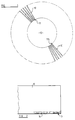
- Figure 1 illustrates an example of a rotor from a turbine and comprises a plurality of turbine blades 10 having a root part 11 by which the turbine blades are attached to a rotor 12.
- the blades may be interconnected by lacing wires and at their outer ends may be connected to a shroud by tenons in conventional manner.
- the turbine blades may be made from a variety of material depending upon the functional operating conditions of the turbine.
- a typical material from which a blade in a steam turbine may be manufactured is chrome steel with approximately 12 - 13% chromium by weight.
- the area of the turbine blade most prone to erosion is illustrated as being the leading edge 13 of the outer end of the turbine blade. It is this part of the blade which collides with steam or particles carried thereby during use of the turbine and which also has the greatest peripheral velocity being the radially outermost point from the axis of rotation.
- the area where erosion is most likely to occur is illustrated at 14 in Figure 2.
- Such a turbine blade can be repaired in a number of different ways depending upon the particular circumstances.
- the modes of repair include removing material, for example by grinding, from the turbine blade in the region 14, the amount of material being removed ensuring that all the damaged material is removed.
- a new hard shield is then built up by deposition of fused metal in a brazing or a welding operation.
- the hard material may, for example, be stellite.
- material may be removed by grinding or cutting from the turbine blade bordering the leading edge 13, again removing all the damaged material, and then welding in place an insert of suitable solid material.
- a composite insert having a leading edge shielded with hard material such as stellite and a trailing part of material compatible with the parent material of the blade and welded thereto.
- a turbine blade is shown at 110 in which a crack 111 has occurred.
- Such a blade is repaired by removing material from the crack as shown by the chain dotted line 112 to form a slot. After the slot has been formed it is closed by deposition of weld material. Thereafter the blade is machined to remove excess weld material and provide a blade of the desired shape.
- the blade may be preheated, and/or during and/or after the performance of a welding or brazing operation.
- the temperature to which different parts of the blade are heated will depend upon the material from which the blade is made, the dimensions of the blade and the type of repair to be carried out.
- the repair method illustrated in Figure 2 may involve pre-heating the blade, for example, to a temperature of about 400°C in the repair area, whilst different parts of the blade may be heated to different temperatures which may be higher or lower.
- the repair method illustrated in Figure 3 may be performed with a pre-heating step of raising the blade to, for example, approximately 200°C.
- the blade may be heated before, during or after completion of the welding operation, for example to a temperature lying in the range of 700°C to 800°C for a predetermined length of time to relieve the blade of any residual stress.
- Material used for the welding process may be of any suitable material compatible with material from which the blade is made, which as mentioned above, may be 12% - 13% chromium steel.
- the welding material may comprise an alloy capable of bonding satisfactorily to the parent metal of the blade by which welding material is inherently more resilient than that of the blade.
- a suitable welding material is Inconel which comprises approximately two thirds nickel, one third chrome plus other metallic elements in small quantities.
- a set of blades are presented for repair (they may be in situ, for example, mounted on the rotor or a stator) it may first be ascertained whether the blades have been thermally hardened, for example by flame hardening or induction hardening.
- the blade is made of relatively low carbon steel, e.g. 12% Cr, 1%C, such a blade would not be thermally hardened. However, if the blade has a relatively higher carbon content, for example 12% Cr, 2%C, it may be thermally hardened. Because such a blade may have a surface layer which gives hardness values which are inconsistent with the hardness of the main body of the blade, the blade is treated to remove a surface layer of, for example, 0.001" - 0.002" thick. Removal of such a surface layer will remove any surface layer having a hardness which is greater than or less than the hardness of the main body of the blade due to, for example, a carburised or decarburised surface layer. The layer is removed in conventional manner by mechanical abrasion with, for example, grinding wheels and/or belt grinders.
- the blade repair requires removal of blade material such as the removal of the material in the region 14 referred to above, or if material has to be ground away in the region of the crack, as shown at 112 above, so as to expose the interior of the blade, this removal is then performed.
- the resultant hardness distribution pattern is then examined and any necessary heat treatment which is required prior to repair can be determined, for example to stress relieve any such thermally hardened blade.
- the blade is then heat treated to stress relieve the blade and subsequently the blade is repaired and stress relieved again, if necessary.
- the or each stress relieving or other heating operation necessary on the blade is performed as hereinafter to be described.
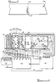
- FIG 4 there is shown an end part of the turbine blade of Figure 2 fitted with heating mats whereby a heating operation can be performed.
- the mats are for pre-heating but essentially the same features as hereinafter to be described apply to any heating operation, although the details of mat size. capacity, position and the electrical energy input, may vary depending upon the particular heating operation to be performed, as well as blade size.
- Figure 5 shows an end part of the blade of Figure 3 similarly fitted with heating mats for the heating operation necessary for that mode of repair.
- the heating mats may be of any suitable form and may comprise, as shown in the heating mat 30, a continuous conductor 36 passing through throughbores in a large number of ceramic beads 37.
- the control circuit 40 has an input 41 to supply the electrical energy to all the heating elements such as the heating element 36 of the mat 30 and a plurality of outputs 42, 43, 44, 45, 46 and 47 so that the energy supplied to each of the heating mats 40 to 35 may be independently controlled.
- the heating control circuit 40 has an input 48 from master control unit 50.
- the master control unit 50 has a power supply 51 and is provided with inputs 52 to 56 from temperature sensing means 57 to 61 respectively.
- Further temperature sensing means 62 and 63 may be provided which provide input signals to the master control circuit 50 at inputs 64 and 65 to alter the energisation of heating mats 30 to 35 should the actual temperature of the turbine blade sensed by sensors 62 and 63 immediately adjacent the area to be repaired either be above or below an expected value due to, for example, unexpected changes in ambient condition or the length of time taken to carry out the brazing or welding operation which may increase or decrease the expected temperature.
- the temperature sensing means 57 - 61 may comprise thermocouples which may be welded to the blade.
- the temperature sensing means 57 - 63 are connected to the master control unit 50 and at least one monitoring means 57 a -63 a is provided associated with each mat and preferably a plurality of monitoring means are provided for at least one of the mats such as the monitoring means 57 a - 57 l shown associated with the mat 31.
- An electrical current of suitably adjusted current and voltage is then supplied to the mats by the unit 40 under the control of the control unit 50 and the resultant temperature distribution is determined by the monitoring means 57 a - l , 58 a - 63 a , the output of all of which can be recorded if desired, for example, using a chart recorder.
- the heat treatment is to cause metallurgical change, for example if it is to be a stress relief heat treatment, the heat applied at this stage is less than that which will cause metallurgical change, for example 200 - 300°C.
- the capacity, size, and distribution of the mats, as well as the electrical energy input are adjusted as necessary empirically until the desired temperature distribution is achieved. Then the temperature is increased to that required to effect the necessary heat treatment then the blade temperature distribution is again monitored to ensure that the desired temperature distribution is achieved.
- the relevant parameters of the heating means are noted as a heating specification.
- the master control unit 50 can be programmed either manually or be supplied with recorded information from past analysis to control the signal supplied to input 48 of heating control circuit 40 so as to control each of the heating mats 30 to 35 with the amount of energy required to produce the desired temperature in the turbine blade 10.
- sensors 57 to 61 can alter the signal produced by master unit 50 to heating control 40 so as to bring the temperature into line by altering the energisation of heating mats 30 to 35 to bring the temperature to its desired value.
- the hardness of the blade may be again checked.
- the relevant parameters of the heating means are noted as a heating specification.
- all the blades, or at least a plurality of the blades presented for repair are then heat treated, preferably at the same time, by replicating the heating specification that is by positioning similar mats in the same way and using the same electrical input to the mats as that used for the heat treatment of the sample blade.
- a plurality of monitoring means such as the sensors 57 a - l , are not necessary for each blade since it has been determined for the sample blade that the appropriate temperature distribution is achieved with the particular mat arrangement and energy input so long as the heating specification is replicated for all the blades.
- a monitoring means is provided for each of the heat sensors 57 - 63.
- the monitoring means comprises a single temperature sensitive device 57 a - 63 a separate from the temperature sensing means constituting the heat sensors 57 - 63.
- the temperature sensitive devices may each comprise, for example, a thermocouple which may be welded to the blade. If desired, more than one such temperature sensitive device may be provided for each heat sensor 57 - 63.
- thermocouples are positioned adjacent a respective temperature sensing means 57 - 63 and are positioned in such proximity to the temperature sensitive means that the repeatability of temperature readings can be ensured.
- a monitoring means such as the monitoring means 57 a - l , 58 a - 63 a is used, since the temperature at such location in relation to the respective temperature sensing means 57 - 63 is known.
- the temperature of the blade at said location adjacent the position of the temperature sensing means 57 - 63 may not be the same as at the respective positions.
- the temperature sensed by the monitoring means 57 a - 63 a may be higher or lower than the temperature sensed by the associated temperature sensing means 57 - 63.
- the monitoring means 57 a - 63 a are connected to inputs 57 b - 63 b respectively of a monitoring circuit 70.
- the monitoring circuit 70 may be arranged to perform one or more of the following functions.
- the monitoring means 57 a - 63 a may be manually connected to the master control unit 50 in place of an input 52 - 56 from a temperature sensing means 57 - 61 which has failed.
- the monitoring means 57 a - 63 a are positioned adjacent to and in proximity to the temperature sensing means 57 - 63 at predetermined positions, which positions generally have been predetermined on the basis of empirical tests, as described above, to ensure that the temperature sensed by the monitoring means accurately reflect either directly, or indirectly with a suitable adjustment factor, the temperature at the position of the associated temperature sensing means.
- the monitoring means enables the temperature as sensed by each temperature sensing means to be checked so that failure of one or more of the temperature sensing means does not lead to incorrect heat treatment of the blade.
- turbine blade 110 shown in Figure 3 is provided with electrical heating elements 113, 114 which is supplied with current by a control unit similar to the master unit 50 under the control of sensing signals derived from temperature sensing means similar to the temperature sensing means 57 - 63 and monitored by monitoring means similar to the monitoring means 57 a - 63 a described hereinbefore and connected to a monitoring circuit similar to the circuit 70 described hereinbefore.
- the building up the new shield 17 to the turbine blade 10 by welding or other welding or brazing operation is performed.
- the heating mats 30 to 35 may be energised or, since the heat capacity of the blade may be considerable energisation may be terminated at this stage and the cooling process begun.
- the blade may now be subjected to further heat treatment from the heating mats 30 to 35 such as a stress relief operation.
- a stress relief operation it may be desirable to maintain a maximum heated temperature of the blade for a certain period of time and then gradually decrease the temperature of the blade over a predetermined time period.
- a heating specification suitable for each heating operation is determined for a sample blade as necessary in a manner similar to that described above.
- the hardness of a blade may be tested at each relevant stage, e.g. initially, after initial stress-relief, after repair and after further stress-relief, or after a desired one or combination of such steps.
- After final heat treatment the positions at which the temperature sensing means 57 - 63 and monitoring means 57 a - l , 58 a - 63 a have been welded to the blade are removed by mechanical abrasion.
- a 0.001" - 0.002" layer may be removed over the whole blade surface prior to final hardness testing.
- a heating specification is determined empirically, where blades to be heated are the same as, or are similar to previously heated blades, a previously known heating specification may be used for all the blades, with or without performing a trial on a sample blade. Further, if desired, in a suitable case, a heating specification may be calculated rather than empirically derived and such a calculated heating specification may be used for all the blades, with or without performing a trial on a sample blade.
Landscapes
- Engineering & Computer Science (AREA)
- Mechanical Engineering (AREA)
- Physics & Mathematics (AREA)
- Plasma & Fusion (AREA)
- Turbine Rotor Nozzle Sealing (AREA)
- Coating By Spraying Or Casting (AREA)
- Excavating Of Shafts Or Tunnels (AREA)
- Shovels (AREA)
- Working Measures On Existing Buildindgs (AREA)
- Control Of Turbines (AREA)
Applications Claiming Priority (3)
| Application Number | Priority Date | Filing Date | Title |
|---|---|---|---|
| GB9210191 | 1992-05-12 | ||
| GB929210191A GB9210191D0 (en) | 1992-05-12 | 1992-05-12 | Turbine blade repair |
| PCT/GB1993/000967 WO1993023198A1 (en) | 1992-05-12 | 1993-05-11 | Turbine blade repair |
Publications (2)
| Publication Number | Publication Date |
|---|---|
| EP0640023A1 EP0640023A1 (en) | 1995-03-01 |
| EP0640023B1 true EP0640023B1 (en) | 1999-03-24 |
Family
ID=10715382
Family Applications (1)
| Application Number | Title | Priority Date | Filing Date |
|---|---|---|---|
| EP93910178A Expired - Lifetime EP0640023B1 (en) | 1992-05-12 | 1993-05-11 | Turbine blade repair |
Country Status (8)
| Country | Link |
|---|---|
| US (1) | US5606796A (enExample) |
| EP (1) | EP0640023B1 (enExample) |
| AT (1) | ATE177981T1 (enExample) |
| AU (1) | AU4078693A (enExample) |
| DE (1) | DE69324138T2 (enExample) |
| GB (2) | GB9210191D0 (enExample) |
| IN (1) | IN181974B (enExample) |
| WO (1) | WO1993023198A1 (enExample) |
Families Citing this family (16)
| Publication number | Priority date | Publication date | Assignee | Title |
|---|---|---|---|---|
| US5712346A (en) * | 1995-02-14 | 1998-01-27 | Avery Dennison Corporation | Acrylic emulsion coatings |
| US5691069A (en) * | 1995-02-14 | 1997-11-25 | Avery Dennison Corporation | Acrylic emulsion coatings for rubber articles |
| US6115917A (en) * | 1998-10-20 | 2000-09-12 | General Electric Company | Single position turbine rotor repair method |
| WO2000032827A1 (fr) * | 1998-12-02 | 2000-06-08 | Sanyo Machine Works, Ltd. | Procede et dispositif de controle de la temperature d'echauffement d'une piece a travailler dans la trempe au chalumeau |
| US6605160B2 (en) * | 2000-08-21 | 2003-08-12 | Robert Frank Hoskin | Repair of coatings and surfaces using reactive metals coating processes |
| DE10143652B4 (de) * | 2000-09-06 | 2011-02-03 | Volkswagen Ag | Verfahren zum Induktionshärten von Werkstücken |
| US6520836B2 (en) * | 2001-02-28 | 2003-02-18 | General Electric Company | Method of forming a trailing edge cutback for a turbine bucket |
| US7009137B2 (en) | 2003-03-27 | 2006-03-07 | Honeywell International, Inc. | Laser powder fusion repair of Z-notches with nickel based superalloy powder |
| US8342386B2 (en) * | 2006-12-15 | 2013-01-01 | General Electric Company | Braze materials and processes therefor |
| WO2010050834A1 (en) * | 2008-11-03 | 2010-05-06 | Instituto De Soldadura E Qualidade | System and process for automatic determination of welding parameters for automated friction stir welding |
| US9260978B2 (en) | 2012-03-19 | 2016-02-16 | General Electric Company | System and method for heating a stator segment |
| US9174309B2 (en) * | 2012-07-24 | 2015-11-03 | General Electric Company | Turbine component and a process of fabricating a turbine component |
| US10293437B2 (en) | 2012-10-12 | 2019-05-21 | United Technologies Corporation | Method of working a gas turbine engine airfoil |
| KR20160105502A (ko) * | 2014-02-13 | 2016-09-06 | 쥬코쿠 덴료쿠 가부시키 가이샤 | 주강 부재의 보수 방법 |
| US11459908B2 (en) * | 2018-08-31 | 2022-10-04 | General Electric Company | CMC component including directionally controllable CMC insert and method of fabrication |
| CN116352368B (zh) * | 2023-05-12 | 2025-08-12 | 安徽马钢设备检修有限公司 | 一种电炉上预热段进料u形槽体开裂焊接装置以及工艺 |
Family Cites Families (7)
| Publication number | Priority date | Publication date | Assignee | Title |
|---|---|---|---|---|
| DE2809089A1 (de) * | 1978-03-02 | 1979-09-13 | Cooper Ind Inc | Loetwerkzeug mit temperaturregelung |
| DE3100273A1 (de) * | 1981-01-08 | 1982-08-19 | László von Dipl.-Phys. 4190 Kleve Körtvélyessy | Ausfall- und driftsicherer temperaturregler |
| US4611744A (en) * | 1982-06-23 | 1986-09-16 | Refurbished Turbine Components Ltd. | Turbine blade repair |
| GB2198667B (en) * | 1986-12-20 | 1991-08-07 | Refurbished Turbine Components | Parts for and methods of repairing machines |
| US5210946A (en) * | 1992-06-26 | 1993-05-18 | Hudson Products Corporation | Leading edge protection for fan blade |
| US5351395A (en) * | 1992-12-30 | 1994-10-04 | General Electric Company | Process for producing turbine bucket with water droplet erosion protection |
| DE4310896C1 (de) * | 1993-04-02 | 1994-03-24 | Thyssen Industrie | Verfahren zum Herstellen von verschleißfesten Kanten an Turbinenschaufeln |
-
1992
- 1992-05-12 GB GB929210191A patent/GB9210191D0/en active Pending
-
1993
- 1993-05-11 AT AT93910178T patent/ATE177981T1/de not_active IP Right Cessation
- 1993-05-11 WO PCT/GB1993/000967 patent/WO1993023198A1/en not_active Ceased
- 1993-05-11 US US08/335,794 patent/US5606796A/en not_active Expired - Fee Related
- 1993-05-11 AU AU40786/93A patent/AU4078693A/en not_active Abandoned
- 1993-05-11 DE DE69324138T patent/DE69324138T2/de not_active Expired - Fee Related
- 1993-05-11 GB GB9309678A patent/GB2266953B/en not_active Expired - Fee Related
- 1993-05-11 EP EP93910178A patent/EP0640023B1/en not_active Expired - Lifetime
- 1993-05-12 IN IN320MA1993 patent/IN181974B/en unknown
Also Published As
| Publication number | Publication date |
|---|---|
| US5606796A (en) | 1997-03-04 |
| GB9210191D0 (en) | 1992-06-24 |
| WO1993023198A1 (en) | 1993-11-25 |
| ATE177981T1 (de) | 1999-04-15 |
| DE69324138T2 (de) | 1999-10-28 |
| AU4078693A (en) | 1993-12-13 |
| GB2266953A (en) | 1993-11-17 |
| DE69324138D1 (de) | 1999-04-29 |
| IN181974B (enExample) | 1998-11-21 |
| GB2266953B (en) | 1995-02-22 |
| EP0640023A1 (en) | 1995-03-01 |
| GB9309678D0 (en) | 1993-06-23 |
Similar Documents
| Publication | Publication Date | Title |
|---|---|---|
| EP0640023B1 (en) | Turbine blade repair | |
| EP0101164B1 (en) | Turbine blade repair | |
| US4832252A (en) | Parts for and methods of repairing turbine blades | |
| CA2648715C (en) | Surface treatment apparatus and method | |
| EP1247003B1 (en) | Turbine blade and method of repair | |
| US5914055A (en) | Rotor repair system and technique | |
| CA1189692A (en) | Turbine blade repair | |
| CN100546756C (zh) | 修理单片叶片转盘的方法,起始和终了测试片 | |
| RU2196671C2 (ru) | Способ ремонта изделия из легированной стали посредством сварки | |
| WO2010036430A2 (en) | Imparting deep compressive residual stresses into a gas turbine engine airfoil peripheral repair weldment | |
| JPH11270350A (ja) | タ―ボ機械構成体の現場修理方法 | |
| US8266800B2 (en) | Repair of nickel-based alloy turbine disk | |
| JPH04282455A (ja) | 構造部品の保守管理方法およびその保守管理装置 | |
| EP0512838A1 (en) | Parts for and methods of repairing turbine blades | |
| JP3909810B2 (ja) | 原動機部品の材料劣化・損傷回復処理方法 | |
| US6047474A (en) | Method of manufacturing a bimetallic turbine blade and use thereof | |
| KR102702656B1 (ko) | 터빈의 버켓 커버 용접 방법 및 회전체 구조물의 정비 신뢰성 평가 방법 | |
| Parker et al. | Microstructure and performance of 1.25 Cr0. 5Mo steel weldments | |
| Mazur et al. | Welding repair of steam and gas turbine rotors made of Cr‐Mo‐V steel | |
| CN120002307A (zh) | 一种航空发动机叶片叶冠耐磨层磨损的修复方法 | |
| WO2004065051A1 (en) | Turbine refurbishment | |
| WO2020154453A1 (en) | Weld-brazing techniques | |
| Storch et al. | Repair welds in turbine blades | |
| McGraw et al. | Repair of Advanced Gas Turbine Blades |
Legal Events
| Date | Code | Title | Description |
|---|---|---|---|
| PUAI | Public reference made under article 153(3) epc to a published international application that has entered the european phase |
Free format text: ORIGINAL CODE: 0009012 |
|
| 17P | Request for examination filed |
Effective date: 19941108 |
|
| AK | Designated contracting states |
Kind code of ref document: A1 Designated state(s): AT BE CH DE FR IT LI LU NL |
|
| 17Q | First examination report despatched |
Effective date: 19960424 |
|
| GRAG | Despatch of communication of intention to grant |
Free format text: ORIGINAL CODE: EPIDOS AGRA |
|
| GRAG | Despatch of communication of intention to grant |
Free format text: ORIGINAL CODE: EPIDOS AGRA |
|
| GRAG | Despatch of communication of intention to grant |
Free format text: ORIGINAL CODE: EPIDOS AGRA |
|
| GRAH | Despatch of communication of intention to grant a patent |
Free format text: ORIGINAL CODE: EPIDOS IGRA |
|
| GRAH | Despatch of communication of intention to grant a patent |
Free format text: ORIGINAL CODE: EPIDOS IGRA |
|
| GRAA | (expected) grant |
Free format text: ORIGINAL CODE: 0009210 |
|
| AK | Designated contracting states |
Kind code of ref document: B1 Designated state(s): AT BE CH DE FR IT LI LU NL |
|
| REF | Corresponds to: |
Ref document number: 177981 Country of ref document: AT Date of ref document: 19990415 Kind code of ref document: T |
|
| REG | Reference to a national code |
Ref country code: CH Ref legal event code: EP |
|
| REF | Corresponds to: |
Ref document number: 69324138 Country of ref document: DE Date of ref document: 19990429 |
|
| ET | Fr: translation filed | ||
| REG | Reference to a national code |
Ref country code: CH Ref legal event code: NV Representative=s name: ISLER & PEDRAZZINI AG |
|
| PLBE | No opposition filed within time limit |
Free format text: ORIGINAL CODE: 0009261 |
|
| STAA | Information on the status of an ep patent application or granted ep patent |
Free format text: STATUS: NO OPPOSITION FILED WITHIN TIME LIMIT |
|
| 26N | No opposition filed | ||
| PGFP | Annual fee paid to national office [announced via postgrant information from national office to epo] |
Ref country code: NL Payment date: 20060503 Year of fee payment: 14 |
|
| PGFP | Annual fee paid to national office [announced via postgrant information from national office to epo] |
Ref country code: DE Payment date: 20060508 Year of fee payment: 14 |
|
| PGFP | Annual fee paid to national office [announced via postgrant information from national office to epo] |
Ref country code: AT Payment date: 20060511 Year of fee payment: 14 |
|
| PGFP | Annual fee paid to national office [announced via postgrant information from national office to epo] |
Ref country code: FR Payment date: 20060515 Year of fee payment: 14 Ref country code: CH Payment date: 20060515 Year of fee payment: 14 |
|
| PGFP | Annual fee paid to national office [announced via postgrant information from national office to epo] |
Ref country code: IT Payment date: 20060531 Year of fee payment: 14 |
|
| PGFP | Annual fee paid to national office [announced via postgrant information from national office to epo] |
Ref country code: LU Payment date: 20060607 Year of fee payment: 14 |
|
| PGFP | Annual fee paid to national office [announced via postgrant information from national office to epo] |
Ref country code: BE Payment date: 20060712 Year of fee payment: 14 |
|
| REG | Reference to a national code |
Ref country code: CH Ref legal event code: PCAR Free format text: ISLER & PEDRAZZINI AG;POSTFACH 1772;8027 ZUERICH (CH) |
|
| BERE | Be: lapsed |
Owner name: *TURBINE BLADING LTD Effective date: 20070531 |
|
| REG | Reference to a national code |
Ref country code: CH Ref legal event code: PL |
|
| PG25 | Lapsed in a contracting state [announced via postgrant information from national office to epo] |
Ref country code: NL Free format text: LAPSE BECAUSE OF NON-PAYMENT OF DUE FEES Effective date: 20071201 |
|
| NLV4 | Nl: lapsed or anulled due to non-payment of the annual fee |
Effective date: 20071201 |
|
| PG25 | Lapsed in a contracting state [announced via postgrant information from national office to epo] |
Ref country code: AT Free format text: LAPSE BECAUSE OF NON-PAYMENT OF DUE FEES Effective date: 20070511 Ref country code: LI Free format text: LAPSE BECAUSE OF NON-PAYMENT OF DUE FEES Effective date: 20070531 Ref country code: CH Free format text: LAPSE BECAUSE OF NON-PAYMENT OF DUE FEES Effective date: 20070531 |
|
| REG | Reference to a national code |
Ref country code: FR Ref legal event code: ST Effective date: 20080131 |
|
| PG25 | Lapsed in a contracting state [announced via postgrant information from national office to epo] |
Ref country code: BE Free format text: LAPSE BECAUSE OF NON-PAYMENT OF DUE FEES Effective date: 20070531 |
|
| PG25 | Lapsed in a contracting state [announced via postgrant information from national office to epo] |
Ref country code: DE Free format text: LAPSE BECAUSE OF NON-PAYMENT OF DUE FEES Effective date: 20071201 |
|
| PG25 | Lapsed in a contracting state [announced via postgrant information from national office to epo] |
Ref country code: FR Free format text: LAPSE BECAUSE OF NON-PAYMENT OF DUE FEES Effective date: 20070531 |
|
| PG25 | Lapsed in a contracting state [announced via postgrant information from national office to epo] |
Ref country code: LU Free format text: LAPSE BECAUSE OF NON-PAYMENT OF DUE FEES Effective date: 20070511 |
|
| PG25 | Lapsed in a contracting state [announced via postgrant information from national office to epo] |
Ref country code: IT Free format text: LAPSE BECAUSE OF NON-PAYMENT OF DUE FEES Effective date: 20070511 |