EP0639418B1 - Rundlaufendes Schneidwerkzeug mit Wendeplattenbestückung, insbesondere zur Metallbearbeitung - Google Patents
Rundlaufendes Schneidwerkzeug mit Wendeplattenbestückung, insbesondere zur Metallbearbeitung Download PDFInfo
- Publication number
- EP0639418B1 EP0639418B1 EP94110162A EP94110162A EP0639418B1 EP 0639418 B1 EP0639418 B1 EP 0639418B1 EP 94110162 A EP94110162 A EP 94110162A EP 94110162 A EP94110162 A EP 94110162A EP 0639418 B1 EP0639418 B1 EP 0639418B1
- Authority
- EP
- European Patent Office
- Prior art keywords
- insert
- tool
- fitting
- cutting tool
- inserts
- Prior art date
- Legal status (The legal status is an assumption and is not a legal conclusion. Google has not performed a legal analysis and makes no representation as to the accuracy of the status listed.)
- Expired - Lifetime
Links
Images



Classifications
-
- B—PERFORMING OPERATIONS; TRANSPORTING
- B23—MACHINE TOOLS; METAL-WORKING NOT OTHERWISE PROVIDED FOR
- B23C—MILLING
- B23C5/00—Milling-cutters
- B23C5/02—Milling-cutters characterised by the shape of the cutter
- B23C5/10—Shank-type cutters, i.e. with an integral shaft
- B23C5/109—Shank-type cutters, i.e. with an integral shaft with removable cutting inserts
-
- B—PERFORMING OPERATIONS; TRANSPORTING
- B23—MACHINE TOOLS; METAL-WORKING NOT OTHERWISE PROVIDED FOR
- B23C—MILLING
- B23C5/00—Milling-cutters
- B23C5/16—Milling-cutters characterised by physical features other than shape
- B23C5/20—Milling-cutters characterised by physical features other than shape with removable cutter bits or teeth or cutting inserts
- B23C5/22—Securing arrangements for bits or teeth or cutting inserts
- B23C5/2204—Securing arrangements for bits or teeth or cutting inserts with cutting inserts clamped against the walls of the recess in the cutter body by a clamping member acting upon the wall of a hole in the insert
- B23C5/2208—Securing arrangements for bits or teeth or cutting inserts with cutting inserts clamped against the walls of the recess in the cutter body by a clamping member acting upon the wall of a hole in the insert for plate-like cutting inserts
-
- B—PERFORMING OPERATIONS; TRANSPORTING
- B23—MACHINE TOOLS; METAL-WORKING NOT OTHERWISE PROVIDED FOR
- B23C—MILLING
- B23C2250/00—Compensating adverse effects during milling
- B23C2250/12—Cooling and lubrication
-
- Y—GENERAL TAGGING OF NEW TECHNOLOGICAL DEVELOPMENTS; GENERAL TAGGING OF CROSS-SECTIONAL TECHNOLOGIES SPANNING OVER SEVERAL SECTIONS OF THE IPC; TECHNICAL SUBJECTS COVERED BY FORMER USPC CROSS-REFERENCE ART COLLECTIONS [XRACs] AND DIGESTS
- Y10—TECHNICAL SUBJECTS COVERED BY FORMER USPC
- Y10T—TECHNICAL SUBJECTS COVERED BY FORMER US CLASSIFICATION
- Y10T407/00—Cutters, for shaping
- Y10T407/19—Rotary cutting tool
- Y10T407/1906—Rotary cutting tool including holder [i.e., head] having seat for inserted tool
- Y10T407/1908—Face or end mill
- Y10T407/191—Plural simultaneously usable separable tools in common seat or common clamp actuator for plural simultaneously usable tools
-
- Y—GENERAL TAGGING OF NEW TECHNOLOGICAL DEVELOPMENTS; GENERAL TAGGING OF CROSS-SECTIONAL TECHNOLOGIES SPANNING OVER SEVERAL SECTIONS OF THE IPC; TECHNICAL SUBJECTS COVERED BY FORMER USPC CROSS-REFERENCE ART COLLECTIONS [XRACs] AND DIGESTS
- Y10—TECHNICAL SUBJECTS COVERED BY FORMER USPC
- Y10T—TECHNICAL SUBJECTS COVERED BY FORMER US CLASSIFICATION
- Y10T407/00—Cutters, for shaping
- Y10T407/19—Rotary cutting tool
- Y10T407/1906—Rotary cutting tool including holder [i.e., head] having seat for inserted tool
- Y10T407/1934—Rotary cutting tool including holder [i.e., head] having seat for inserted tool with separate means to fasten tool to holder
- Y10T407/1936—Apertured tool
-
- Y—GENERAL TAGGING OF NEW TECHNOLOGICAL DEVELOPMENTS; GENERAL TAGGING OF CROSS-SECTIONAL TECHNOLOGIES SPANNING OVER SEVERAL SECTIONS OF THE IPC; TECHNICAL SUBJECTS COVERED BY FORMER USPC CROSS-REFERENCE ART COLLECTIONS [XRACs] AND DIGESTS
- Y10—TECHNICAL SUBJECTS COVERED BY FORMER USPC
- Y10T—TECHNICAL SUBJECTS COVERED BY FORMER US CLASSIFICATION
- Y10T407/00—Cutters, for shaping
- Y10T407/22—Cutters, for shaping including holder having seat for inserted tool
- Y10T407/2272—Cutters, for shaping including holder having seat for inserted tool with separate means to fasten tool to holder
- Y10T407/2274—Apertured tool
- Y10T407/2276—Apertured tool with means projecting through aperture to force tool laterally against reaction surface
Definitions
- the invention relates to a concentric cutting tool with insert, especially for metal processing, with a tool body that at least one for Inclusion of an insert fitted with an insert has, in which lying on a support surface Indexable insert in radial and axial directions is dimensionally supported laterally, the indexable insert as a perforated plate with a countersunk through Bore formed and by means of an associated in a corresponding threaded hole of the tool body or a part screwed into this, one Clamping screw with clamping head in the insert seat is releasably tensioned; see e.g. DE-A 2906 148.
- the indexable inserts to achieve a flawless Function of the tool in the associated insert seats be fixed in the correct position on the tool body, so that exactly tolerated concentricity and axial runout of the working cutting result.
- This is often done, for example with shoulder milling cutters or with spiral toothing Milling the tool body with so-called closed Plate seats formed, that is, pocket-like recesses with an indexable insert contact surface that in the radial and axial direction by a dimensionally accurate Side area is limited, which is a stop for the indexable insert resting on the contact surface forms.
- a design of the seat at which is the dimensionally accurate stop for those on the contact surface overlying insert is formed by a pin is either essentially radial or tangential inserted into a corresponding hole in the tool body is and if necessary a precisely machined contact surface for the indexable insert.
- the object of the invention is therefore to ensure that it runs smoothly Cutting tool, in particular a drill or To create milling cutter in the face of the aforementioned difficulties is remedied and that by a flawless, dimensionally accurate tension of the perforated plates Indexable inserts with unimpeded clamping sequence and low manufacturing and assembly costs.
- the above is Cutting tool characterized in that the in the Insert inserted insert transverse to Hole axis only in one direction on a tool body fixed Stop and in the other direction alone supported by the clamping screw in a form-fitting manner is.
- the clamping screw is preferred Embodiment as a fitting screw with one in one the threaded bore coaxial fitting bore of the tool body or the part closely associated with this engaging fitting part.
- the clamping head of the clamping screw can in itself be any be formed, for example conical, spherical, concave, convex or cylindrical with offset, while the fitting part the fitting screw is usually cylindrical.
- the diameter the protruding into the hole of the insert Part of the fitting screw is consistently smaller than the diameter the area of the hole in the insert that surrounds it, so that when the clamping screw is tightened only the clamping head on the opening wall the perforated plate bears at least essentially on all sides.
- the milling tool is the respective indexable insert consistently only in the radial direction on a tool body fixed Stop supported while the tension screw the positive support in the axial direction and at the same time the pressure on the insert against the tool body fixed stop and the tension the tool plate against its bearing surface in the plate seat takes over.
- the concentric cutting tool shown in Figs. 1-3 is a spiral toothed cutter especially for Circular and trimming milling work on metallic workpieces. It has a substantially cylindrical Tool body 1, one with a driving groove 2 provided ring flange 3 and then one Short cone 4 for connection to the not shown Recording carries.
- the tool body made of steel 1 is spiraling on the left with four spiral flutes 5 with the same pitch and with square or parallelogram-shaped indexable inserts 6 equipped, through the four assigned to the flutes 5 Rows of cutting edges are formed.
- the indexable inserts 6 are of this type for this purpose arranged that mutually adjacent indexable inserts 6 each row of cutting edges overlap in the axial direction, see above that each row of cutting edges is a so-called closed Cutting edge row is.
- Embodiments are also common in which the Inserts 6 adjacent rows of cutting edges Gap to each other, such that there are always two rows of cutting edges resulting in a complete row of cutting edges form.
- Each row of cutting edges contains an angular insert 6a, with a cutting edge 7a over the Front surface 8 of the tool body 1 protrudes, all Face cutting 7a lie in a common area, the 5, 6 at 9 is indicated by dash-dotted lines.
- the Main or peripheral cutting 7 of the indexable inserts 6, 6a each describe the same flight circle 14 (FIG. 4).
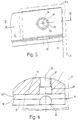
- Each of the indexable inserts 6, 6a is in a groove or pocket-shaped plate seat 10 added to the Area of the substantially radial to the axis of rotation 11 of the Tool body 1 directed wall 12 of the associated Flute 5 is arranged.
- each plate seat 10 has a plane Contact surface 13 for an indexable insert 6, 6a.
- the support surface 13 is with respect to the axis of rotation 11 such an orientation in space that the with their main or peripheral cutting edge 7 on the same Flight circle 14 running indexable inserts 6, 6a with the correct cutting edge geometry, i.e. each with predetermined Axis and radial angles work.
- the bearing surface 13 closes on the axis of rotation 11 adjacent side to a side wall 16, the one at least over the length of the indexable insert 6, 6a includes extending plant surface area 17, which acts as a radial stop for the bearing surface 13 attached indexable insert 6, 6a is used.
- the contact area 17 corresponds to the inclination of the open area 18 (FIG. 4) of the indexable insert designed as a positive insert 6, 6a inclined so that a precise correct position System of the insert is guaranteed.
- the Contact area 17 extends over only part of the height of the side wall 16; it borders on one surface area standing at right angles to the support surface 13 19 at the distance from the open area 18 of the inserted indexable insert 6, 6a stands and thus ensures that the insert 6, 6a works properly be held in the plant area area 17 can.
- One worked into the side wall 16 from above groove-shaped recess 20 (Fig. 5, 6) divides the Contact surface area 17 in approximately two parts of equal length, thereby preventing the certain inevitable Indexable insert 6 with manufacturing tolerances, 6a rises in the middle of the contact surface area 17, which would lead to undefined investment conditions.
- Each of the indexable inserts 6, 6a which are basically square (Fig. 1), rectangular parallelogram or polygonal (indicated by dash-dotted lines in FIGS. 5, 6) can be designed as a perforated plate with a continuous, essentially cylindrical bore 22nd trained, towards which to the top of the plate Slightly convex curved conical bore part in cross section 23 which connects to a countersink 24 expanded.
- this perforated plate in the respective plate seat 10 serves a fitting screw 25, which in the 4 apparent with a threaded part 26 in a threaded hole 27 associated with the plate seat 10 Tool body 1 is screwed.
- the fitting screw 25 has one of the threaded part 26 a threaded outlet groove separate, dimensionally accurate cylindrical Fitting part 28, which tolerates tight in the assembled state in a cylindrical to the threaded bore 27 coaxial Fitting bore 29 of the tool body 1 is inserted.
- a chuck 31 which has a substantially conical clamping surface 32 carries that in the assembled state on the conical surface 23 of the indexable insert rests, as shown in FIG. 4 is illustrated.
- the axis perpendicular to the support surface 13 33 of the threaded bore 27 and the fitting bore 29 is in Direction towards the contact surface area 17 against the Hole axis 34 of the insert 6, 6a slightly offset (Fig. 4.5) such that when the fitting screw 25 is tightened on the indexable insert 6, 6a on the system surface area 17 to be directed transversely to the hole axis 34 oriented contact pressure is exerted under their effect the indexable insert is pretensioned against the contact surface area 17 is pressed.
- FIG Milling cutter represented in its basic Structure of the left-hand spiral milling cutter according to FIGS. 1 - 6 corresponds. It is also with four rows of blades educated. The same parts are therefore the same Provide reference numerals and not explained again.
- the threaded holes 27 and the fitting holes 29 are at the embodiments directly in the tool body 1 arranged. Especially for larger tools Diameter, it may be appropriate to the plate seat 10th each in a separate part of a so-called cassette to arrange, which in turn with the tool body screwed or otherwise attached to it. In such cases are then threaded and fitting holes respectively provided in the cassette.
- the axis 33 of the threaded bore 27 and the fitting bore 29 runs at right angles to the contact surface 13 of the respective indexable insert 6, 6a.
- the axis 33 forms a certain angle deviating from 90 ° with the support surface 13, for example in order to press the indexable insert against a radial stop during clamping.
- the tool body 1 is finally provided with a coolant channel 35, from which branch channels 36 lead to coolant outlets in the vicinity of the indexable inserts 6.
Landscapes
- Engineering & Computer Science (AREA)
- Mechanical Engineering (AREA)
- Milling Processes (AREA)
- Cutting Tools, Boring Holders, And Turrets (AREA)
Description
- Fig. 1
- einen linksspiraligen, rechtsschneidenden wendeplattenbestückten Fräser gemäß der Erfindung mit vier Schneidenreihen, in schematischer perspektivischer Darstellung,
- Fig. 2
- den Fräser nach Fig. 1 in einer Seitenansicht, teilweise im axialen Schnitt,
- Fig. 3
- den Fraser nach Fig. 1 in der Draufsicht auf die Stirnseite,
- Fig. 4
- einen Ausschnitt aus dem Fräser nach Fig. 1 unter Veranschaulichung eines Plattensitzes mit eingesetzter Wendeschneidplatte, in einer Seitenansicht und in einem anderen Maßstab,
- Fig. 5
- den Plattensitz nach Fig. 4 in der Draufsicht auf die Auflagefläche für die Wendeschneidplatte bei weggelassener Spannschraube
- Fig. 6
- die Anordnung nach Fig. 5, geschnitten längs der Linie VI-VI der Fig. 5 in einer Seitenansicht und im Ausschnitt und
- Fig. 7
- einen rechtsspiraligen, rechtsschneidenden wendeplattenbestückten Fräser gemäß der Erfindung mit vier Schneidereihen in schematischer perspektivischer Darstellung.
Der Werkzeugkörper 1 ist schließlich mit einem Kühlmittelkanal 35 versehen, von dem aus Stichkanäle 36 zu Kühlmittelauslässen in der Nähe der Wendeschneidplatten 6 führen.
Claims (6)
- Rundlaufendes Schneidwerkzeug mit Wendeplattenbestückung (6,6a), insbesondere zur Metallbearbeitung, mit einem Werkzeugkörper (1), der zumindest einen zur Aufnahme einer Wendeschneidplatte eingerichteten Plattensitz (10) aufweist, in dem die auf einer Auflagefläche (13) aufliegende Wendeschneidplatte in radialer und in axialer Richtung maßgenau seitlich abgestützt ist, wobei die Wendeschneidplatte als Lochplatte mit einer angesenkten, durchgehenden Bohrung (22) ausgebildet und mittels einer zugeordneten, in eine entsprechende Gewindebohrung (27) des Werkzeugkörpers oder eines mit diesem verbundenen Teiles eingeschraubten, einen Spannkopf (31) aufweisenden Spannschraube (25) in dem Plattensitz lösbar gespannt ist, dadurch gekennzeichnet, daß die in den Plattensitz (10) eingesetzte Wendeschneidplatte (6, 6a) quer zur Lochachse (34) der Wendeschneidplatte lediglich in einer Richtung an einem werkzeugkörperfesten Anschlag (17) und in der anderen Richtung allein durch die Spannschraube (25) maßgenau formschlüsslg abgestützt ist.
- Schneidwerkzeug nach Anspruch 1 dadurch gekennzeich net, daß die Spannschraube als Paßschraube (25) mit einem in eine zu der Gewindebohrung (27) koaxiale Paßbohrung (29) des Werkzeugkörpers (1) oder des mit diesem verbundenen Teiles eng toleriert eingreifenden Paßteil (28) ausgebildet ist.
- Schneidwerkzeug nach Anspruch 2 dadurch gekennzeichnet, daß die Achse (33) der Paßbohrung (29) gegenüber der Lochachse (34) der Wendeschneidplatte (6,6a) in Richtung auf den werkzeugkörperfesten Anschlag (17) zu versetzt ist.
- Schneidwerkzeug nach einem der vorhergehenden Ansprüche dadurch gekennzeichnet, daß im angezogenen Zustand der Spannschraube (25) lediglich deren Spannkopf (31) an der Öffnungsberandung (23) der Lochplatte(6,6a) zumindest im wesentlichen allseitig anliegt.
- Schneidwerkzeug nach einem der vorhergehenden Ansprüche dadurch gekennzeichnet, daß die Wendeschneidplatte (6,6a) lediglich in radialer Richtung an einem werkzeugkörperfesten Anschlag (17) abgestützt ist.
- Schneidwerkzeug nach einem der vorhergehenden Ansprüche dadurch gekennzeichnet, daß bei der Ausbildung als sowohl am Umfang als auch stirnseitig schneidendes Werkzeug lediglich die stirnseitig schneidenden Wendeschneidplatten (6a) durch ihre jeweilige Spann schraube (25) axial abgestützt sind.
Applications Claiming Priority (2)
| Application Number | Priority Date | Filing Date | Title |
|---|---|---|---|
| DE4325999 | 1993-08-03 | ||
| DE4325999A DE4325999C2 (de) | 1993-08-03 | 1993-08-03 | Rundlaufendes Schneidwerkzeug mit Wendeplattenbestückung, insbesondere zur Metallbearbeitung |
Publications (2)
| Publication Number | Publication Date |
|---|---|
| EP0639418A1 EP0639418A1 (de) | 1995-02-22 |
| EP0639418B1 true EP0639418B1 (de) | 1998-02-04 |
Family
ID=6494337
Family Applications (1)
| Application Number | Title | Priority Date | Filing Date |
|---|---|---|---|
| EP94110162A Expired - Lifetime EP0639418B1 (de) | 1993-08-03 | 1994-06-30 | Rundlaufendes Schneidwerkzeug mit Wendeplattenbestückung, insbesondere zur Metallbearbeitung |
Country Status (6)
| Country | Link |
|---|---|
| US (1) | US5542793A (de) |
| EP (1) | EP0639418B1 (de) |
| JP (1) | JPH0760528A (de) |
| AT (1) | ATE162970T1 (de) |
| DE (2) | DE4325999C2 (de) |
| ES (1) | ES2111804T3 (de) |
Cited By (1)
| Publication number | Priority date | Publication date | Assignee | Title |
|---|---|---|---|---|
| CN102770224A (zh) * | 2010-03-02 | 2012-11-07 | 伊斯卡有限公司 | 具有可调节冷却机构的旋转切削工具 |
Families Citing this family (28)
| Publication number | Priority date | Publication date | Assignee | Title |
|---|---|---|---|---|
| DE10252040B3 (de) * | 2002-11-06 | 2004-01-22 | Manfred Scharmann | Werkzeug zum Schneiden von Gewinden |
| IL104273A (en) * | 1992-12-30 | 1996-01-31 | Iscar Ltd | Double faced cutting insert |
| DE19600636B4 (de) * | 1996-01-10 | 2008-01-31 | Widia Gmbh | Walzenstirnfräser |
| AT1366U1 (de) * | 1996-07-02 | 1997-04-25 | Kraus Hermine | Fräser |
| IL119114A0 (en) * | 1996-08-22 | 1996-11-14 | Iscar Ltd | Cutting insert |
| US5853267A (en) * | 1996-08-22 | 1998-12-29 | Iscar Ltd. | Cutting insert |
| SE510851C2 (sv) * | 1996-12-23 | 1999-06-28 | Sandvik Ab | Skär samt hållare för skärande metallbearbetning |
| ATE202029T1 (de) | 1997-04-12 | 2001-06-15 | Ledermann & Co | Fräswerkzeug zur bearbeitung von werkstücken aus holz, einem holzwerkstoff, einem kunststoff oder dergleichen |
| DE19958636A1 (de) * | 1999-12-04 | 2001-06-07 | Vargus Ltd | Fräswerkzeug und -einsatz, insbesondere Gewindefräser |
| DE50015372D1 (de) * | 2000-07-15 | 2008-11-06 | Aute Autogene Tech | Mechanischer Schälentbarter zum Entfernen von Sauerstoffschneidbärten und -schneidperlen nach dem thermochemischen Querteilen oder Längsteilen von stählernen Werkstücken wie Brammen, Blöcken und Knüppeln |
| DE10043016B4 (de) * | 2000-09-01 | 2006-11-23 | Walter Ag | Bohrnutenfräser |
| SE523655C2 (sv) * | 2001-08-09 | 2004-05-04 | Sandvik Ab | Roterbart skärverktyg med ett skär som är fastspännbart med en partiellt böjlig spännskruv. |
| SE523224C2 (sv) * | 2001-11-21 | 2004-04-06 | Sandvik Ab | Roterbart skärverktyg |
| SE523682C2 (sv) * | 2001-12-07 | 2004-05-11 | Seco Tools Ab | Fräsverktyg anordnat att bearbeta i verktygets axiella riktning |
| US20030190203A1 (en) * | 2002-04-08 | 2003-10-09 | Marusich Troy D. | High frequency tooth pass cutting method |
| US20080056838A1 (en) * | 2002-04-08 | 2008-03-06 | Marusich Troy D | High frequency tooth pass cutting method |
| US20040258496A1 (en) * | 2002-04-08 | 2004-12-23 | Marusich Troy D. | High frequency tooth pass cutting device and method |
| DE10338276B4 (de) * | 2003-08-15 | 2008-05-21 | NUBIUS GROUP Präzisionswerkzeuge GmbH | Fräswerkzeug |
| US20080050185A1 (en) * | 2006-08-23 | 2008-02-28 | Hermance Machine Company | Helical cutterhead |
| US7566192B2 (en) * | 2007-10-19 | 2009-07-28 | Kennametal Inc. | Axial seating pin |
| AT11470U1 (de) * | 2009-06-10 | 2010-11-15 | Ceratizit Austria Gmbh | Schneidwerkzeug |
| IL214781A0 (en) * | 2011-08-22 | 2011-10-31 | Iscar Ltd | Cutting tool and cutting insert therefor |
| EP2954968B1 (de) * | 2014-06-13 | 2021-01-20 | Walter Ag | Gewindefräser |
| AT14369U1 (de) * | 2014-11-24 | 2015-09-15 | Ceratizit Austria Gmbh | Werkzeug für die zerspanende Bearbeitung |
| CN107614173B (zh) * | 2015-09-24 | 2018-12-14 | 三菱日立工具株式会社 | 可转位刀片式切削工具 |
| DE102016104005A1 (de) | 2016-03-04 | 2017-09-07 | Gottfried Wilhelm Leibniz Universität Hannover | Fräswerkzeug |
| US10556278B2 (en) | 2016-08-16 | 2020-02-11 | Kennametal Inc. | Tool body for a shell end mill and cutting tool |
| CN107570735B (zh) * | 2017-09-30 | 2020-04-10 | 株洲钻石切削刀具股份有限公司 | 一种孔内具有圆弧形凹槽的多边形切削刀片及切削刀具 |
Family Cites Families (14)
| Publication number | Priority date | Publication date | Assignee | Title |
|---|---|---|---|---|
| DE1295967B (de) * | 1964-03-30 | 1969-05-22 | Devlieg Machine Co | Spanabhebendes Werkzeug mit auswechselbarem Schneidkoerper |
| US3662444A (en) * | 1970-03-09 | 1972-05-16 | Ingersoll Milling Machine Co | Indexable cutting insert and holder therefor |
| DE2452099B2 (de) * | 1974-11-02 | 1978-06-22 | Karl 8500 Nuernberg Hertel | Spannbolzen für ein Schneidwerkzeug der spanabhebenden Bearbeitung |
| US4182587A (en) * | 1978-04-26 | 1980-01-08 | Ingersoll Maschinen Und Werkzeuge Gmbh | Milling cutter and indexable insert therefor |
| DE2906148A1 (de) * | 1979-02-17 | 1980-08-28 | Walter Gmbh Montanwerke | Schneidwerkzeug mit wendeplattenbestueckung |
| US4398853A (en) * | 1980-11-10 | 1983-08-16 | Kennametal Inc. | Insert holder and method of holding |
| DE3118467A1 (de) * | 1981-05-09 | 1982-11-25 | Fried. Krupp Gmbh, 4300 Essen | "anordnung zur befestigung von auswechselbaren schneidplatten auf einem werkzeughalter" |
| DE3314049A1 (de) * | 1983-04-19 | 1984-10-25 | Montanwerke Walter GmbH, 7400 Tübingen | Wendeschneidplattenbestueckter schaftfraeser |
| IL85606A (en) * | 1988-03-02 | 1994-02-27 | Amram Dotany | Helical cutting tool |
| DE3842209A1 (de) * | 1988-12-15 | 1990-06-21 | Walter Gmbh Montanwerke | Bohrwerkzeug fuer metallische werkstoffe, kunststoffe und dergl. |
| GB9003697D0 (en) * | 1990-02-19 | 1990-04-18 | Iscar Hartmetall | A metal cutting tool |
| JPH03281115A (ja) * | 1990-03-30 | 1991-12-11 | Mitsubishi Materials Corp | スローアウエイ式切削工具 |
| SE9003705L (sv) * | 1990-11-21 | 1992-05-22 | Seco Tools Ab | Skaerverktyg |
| US5346336A (en) * | 1992-11-04 | 1994-09-13 | Sandvik, Inc. | Metal-cutting insert having a round cutting edge |
-
1993
- 1993-08-03 DE DE4325999A patent/DE4325999C2/de not_active Expired - Fee Related
-
1994
- 1994-06-30 AT AT94110162T patent/ATE162970T1/de not_active IP Right Cessation
- 1994-06-30 EP EP94110162A patent/EP0639418B1/de not_active Expired - Lifetime
- 1994-06-30 DE DE59405209T patent/DE59405209D1/de not_active Expired - Fee Related
- 1994-06-30 ES ES94110162T patent/ES2111804T3/es not_active Expired - Lifetime
- 1994-07-25 US US08/280,007 patent/US5542793A/en not_active Expired - Fee Related
- 1994-08-02 JP JP6181600A patent/JPH0760528A/ja active Pending
Cited By (2)
| Publication number | Priority date | Publication date | Assignee | Title |
|---|---|---|---|---|
| CN102770224A (zh) * | 2010-03-02 | 2012-11-07 | 伊斯卡有限公司 | 具有可调节冷却机构的旋转切削工具 |
| CN102770224B (zh) * | 2010-03-02 | 2016-03-16 | 伊斯卡有限公司 | 具有可调节冷却机构的旋转切削工具 |
Also Published As
| Publication number | Publication date |
|---|---|
| JPH0760528A (ja) | 1995-03-07 |
| DE59405209D1 (de) | 1998-03-12 |
| DE4325999A1 (de) | 1995-02-09 |
| US5542793A (en) | 1996-08-06 |
| ATE162970T1 (de) | 1998-02-15 |
| EP0639418A1 (de) | 1995-02-22 |
| DE4325999C2 (de) | 1996-02-15 |
| ES2111804T3 (es) | 1998-03-16 |
Similar Documents
| Publication | Publication Date | Title |
|---|---|---|
| DE4325999C2 (de) | Rundlaufendes Schneidwerkzeug mit Wendeplattenbestückung, insbesondere zur Metallbearbeitung | |
| EP0114297B1 (de) | Zerspanungswerkzeug | |
| EP0472563B1 (de) | Werkzeug mit verstellbarer wechselkassette | |
| DE69807182T2 (de) | Werkzeugkupplung und methode zum kupplung zweier werkzeugelementen | |
| EP1184116B1 (de) | Bohrnutenfräser | |
| DE69718740T2 (de) | Werkzeugmaschinenschneidewerkzeugpositioniervorrichtung | |
| EP0215283B1 (de) | Werkzeugkupplung | |
| EP2301696B1 (de) | Kombination eines Aufnahmekörpers und eines insbesondere als Werkzeug- oder Werkstückhalter ausgebildeten Einsatzes, ein Aufnahmekörper und ein Einsatz für eine solche Kombination | |
| EP1240963B1 (de) | Verbindungsstelle | |
| EP0182290A2 (de) | Messerkopf | |
| EP0674561A1 (de) | Vollbohrer | |
| CH656335A5 (de) | Bohrwerkzeug. | |
| EP0385280A1 (de) | Innendrehmeissel | |
| DE69207464T2 (de) | Schneidwerkzeug | |
| EP0296460B1 (de) | Werkzeug zur umfangsschneidenden Bearbeitung von Werkstücken, insbesondere zum Bohren | |
| EP3668668B1 (de) | Werkzeughalteranordnung und verfahren zum herstellen eines werkzeughalters | |
| EP0749795A1 (de) | Bohrwerkzeug | |
| CH668723A5 (de) | Revolverkopf fuer eine drehmaschine und hierzu passende werkzeughalter. | |
| WO1995029783A1 (de) | Bohrwerkzeug | |
| EP0791421A1 (de) | Verbindung zwischen einem Schneidenhalter und einem Werkzeugträger eines Ausdrehkopfes | |
| EP0175011B1 (de) | Drehbares Zerspanungswerkzeug, insbesondere Ausbohrkopf od.dgl. | |
| DE3232495A1 (de) | Vorrichtung zur kuehlmittelzufuhr zu mit kuehlmittelkanaelen versehenen, rotierenden schneidwerkzeugen fuer die spanende metallbearbeitung, insbesondere bohrwerkzeuge | |
| DE19609904A1 (de) | Werkzeughalter für gerundete Einwegschneidplatten | |
| DE9206148U1 (de) | Kombinationswerkzeug | |
| DE2808866A1 (de) | Bohrwerkzeug fuer bohrungen in metallvollmaterial von werkstuecken |
Legal Events
| Date | Code | Title | Description |
|---|---|---|---|
| PUAI | Public reference made under article 153(3) epc to a published international application that has entered the european phase |
Free format text: ORIGINAL CODE: 0009012 |
|
| AK | Designated contracting states |
Kind code of ref document: A1 Designated state(s): AT BE CH DE DK ES FR GB GR IE IT LI LU MC NL PT SE |
|
| 17P | Request for examination filed |
Effective date: 19950808 |
|
| GRAG | Despatch of communication of intention to grant |
Free format text: ORIGINAL CODE: EPIDOS AGRA |
|
| D17Q | First examination report despatched (deleted) | ||
| GRAG | Despatch of communication of intention to grant |
Free format text: ORIGINAL CODE: EPIDOS AGRA |
|
| GRAG | Despatch of communication of intention to grant |
Free format text: ORIGINAL CODE: EPIDOS AGRA |
|
| GRAH | Despatch of communication of intention to grant a patent |
Free format text: ORIGINAL CODE: EPIDOS IGRA |
|
| GRAH | Despatch of communication of intention to grant a patent |
Free format text: ORIGINAL CODE: EPIDOS IGRA |
|
| GRAA | (expected) grant |
Free format text: ORIGINAL CODE: 0009210 |
|
| AK | Designated contracting states |
Kind code of ref document: B1 Designated state(s): AT BE CH DE DK ES FR GB GR IE IT LI LU MC NL PT SE |
|
| PG25 | Lapsed in a contracting state [announced via postgrant information from national office to epo] |
Ref country code: GR Free format text: LAPSE BECAUSE OF FAILURE TO SUBMIT A TRANSLATION OF THE DESCRIPTION OR TO PAY THE FEE WITHIN THE PRESCRIBED TIME-LIMIT Effective date: 19980204 |
|
| REF | Corresponds to: |
Ref document number: 162970 Country of ref document: AT Date of ref document: 19980215 Kind code of ref document: T |
|
| ITF | It: translation for a ep patent filed | ||
| REG | Reference to a national code |
Ref country code: CH Ref legal event code: NV Representative=s name: KIRKER & CIE SA Ref country code: CH Ref legal event code: EP |
|
| ET | Fr: translation filed | ||
| GBT | Gb: translation of ep patent filed (gb section 77(6)(a)/1977) |
Effective date: 19980206 |
|
| REF | Corresponds to: |
Ref document number: 59405209 Country of ref document: DE Date of ref document: 19980312 |
|
| REG | Reference to a national code |
Ref country code: ES Ref legal event code: FG2A Ref document number: 2111804 Country of ref document: ES Kind code of ref document: T3 |
|
| PG25 | Lapsed in a contracting state [announced via postgrant information from national office to epo] |
Ref country code: PT Free format text: LAPSE BECAUSE OF FAILURE TO SUBMIT A TRANSLATION OF THE DESCRIPTION OR TO PAY THE FEE WITHIN THE PRESCRIBED TIME-LIMIT Effective date: 19980504 Ref country code: DK Free format text: LAPSE BECAUSE OF FAILURE TO SUBMIT A TRANSLATION OF THE DESCRIPTION OR TO PAY THE FEE WITHIN THE PRESCRIBED TIME-LIMIT Effective date: 19980504 |
|
| REG | Reference to a national code |
Ref country code: IE Ref legal event code: FG4D Free format text: 78763 |
|
| PG25 | Lapsed in a contracting state [announced via postgrant information from national office to epo] |
Ref country code: IE Free format text: LAPSE BECAUSE OF NON-PAYMENT OF DUE FEES Effective date: 19980924 |
|
| REG | Reference to a national code |
Ref country code: IE Ref legal event code: FD4D Ref document number: 78763 Country of ref document: IE |
|
| PLBE | No opposition filed within time limit |
Free format text: ORIGINAL CODE: 0009261 |
|
| STAA | Information on the status of an ep patent application or granted ep patent |
Free format text: STATUS: NO OPPOSITION FILED WITHIN TIME LIMIT |
|
| PG25 | Lapsed in a contracting state [announced via postgrant information from national office to epo] |
Ref country code: MC Free format text: LAPSE BECAUSE OF NON-PAYMENT OF DUE FEES Effective date: 19981231 |
|
| 26N | No opposition filed | ||
| REG | Reference to a national code |
Ref country code: GB Ref legal event code: IF02 |
|
| PGFP | Annual fee paid to national office [announced via postgrant information from national office to epo] |
Ref country code: GB Payment date: 20040528 Year of fee payment: 11 |
|
| PGFP | Annual fee paid to national office [announced via postgrant information from national office to epo] |
Ref country code: NL Payment date: 20040530 Year of fee payment: 11 |
|
| PGFP | Annual fee paid to national office [announced via postgrant information from national office to epo] |
Ref country code: LU Payment date: 20040602 Year of fee payment: 11 Ref country code: CH Payment date: 20040602 Year of fee payment: 11 |
|
| PGFP | Annual fee paid to national office [announced via postgrant information from national office to epo] |
Ref country code: SE Payment date: 20040603 Year of fee payment: 11 Ref country code: AT Payment date: 20040603 Year of fee payment: 11 |
|
| PGFP | Annual fee paid to national office [announced via postgrant information from national office to epo] |
Ref country code: FR Payment date: 20040609 Year of fee payment: 11 |
|
| PGFP | Annual fee paid to national office [announced via postgrant information from national office to epo] |
Ref country code: ES Payment date: 20040615 Year of fee payment: 11 |
|
| PGFP | Annual fee paid to national office [announced via postgrant information from national office to epo] |
Ref country code: BE Payment date: 20040709 Year of fee payment: 11 |
|
| PG25 | Lapsed in a contracting state [announced via postgrant information from national office to epo] |
Ref country code: LU Free format text: LAPSE BECAUSE OF NON-PAYMENT OF DUE FEES Effective date: 20050630 Ref country code: LI Free format text: LAPSE BECAUSE OF NON-PAYMENT OF DUE FEES Effective date: 20050630 Ref country code: IT Free format text: LAPSE BECAUSE OF NON-PAYMENT OF DUE FEES;WARNING: LAPSES OF ITALIAN PATENTS WITH EFFECTIVE DATE BEFORE 2007 MAY HAVE OCCURRED AT ANY TIME BEFORE 2007. THE CORRECT EFFECTIVE DATE MAY BE DIFFERENT FROM THE ONE RECORDED. Effective date: 20050630 Ref country code: GB Free format text: LAPSE BECAUSE OF NON-PAYMENT OF DUE FEES Effective date: 20050630 Ref country code: CH Free format text: LAPSE BECAUSE OF NON-PAYMENT OF DUE FEES Effective date: 20050630 Ref country code: BE Free format text: LAPSE BECAUSE OF NON-PAYMENT OF DUE FEES Effective date: 20050630 Ref country code: AT Free format text: LAPSE BECAUSE OF NON-PAYMENT OF DUE FEES Effective date: 20050630 |
|
| PG25 | Lapsed in a contracting state [announced via postgrant information from national office to epo] |
Ref country code: SE Free format text: LAPSE BECAUSE OF NON-PAYMENT OF DUE FEES Effective date: 20050701 Ref country code: ES Free format text: LAPSE BECAUSE OF NON-PAYMENT OF DUE FEES Effective date: 20050701 |
|
| PG25 | Lapsed in a contracting state [announced via postgrant information from national office to epo] |
Ref country code: NL Free format text: LAPSE BECAUSE OF NON-PAYMENT OF DUE FEES Effective date: 20060101 |
|
| REG | Reference to a national code |
Ref country code: CH Ref legal event code: PL |
|
| PG25 | Lapsed in a contracting state [announced via postgrant information from national office to epo] |
Ref country code: FR Free format text: LAPSE BECAUSE OF NON-PAYMENT OF DUE FEES Effective date: 20060228 |
|
| GBPC | Gb: european patent ceased through non-payment of renewal fee |
Effective date: 20050630 |
|
| NLV4 | Nl: lapsed or anulled due to non-payment of the annual fee |
Effective date: 20060101 |
|
| EUG | Se: european patent has lapsed | ||
| REG | Reference to a national code |
Ref country code: FR Ref legal event code: ST Effective date: 20060228 |
|
| REG | Reference to a national code |
Ref country code: ES Ref legal event code: FD2A Effective date: 20050701 |
|
| BERE | Be: lapsed |
Owner name: *WALTER A.G. Effective date: 20050630 |
|
| PGFP | Annual fee paid to national office [announced via postgrant information from national office to epo] |
Ref country code: DE Payment date: 20080630 Year of fee payment: 15 |
|
| PG25 | Lapsed in a contracting state [announced via postgrant information from national office to epo] |
Ref country code: DE Free format text: LAPSE BECAUSE OF NON-PAYMENT OF DUE FEES Effective date: 20100101 |