EP0639358B1 - Prothèse de genou à articulation sphérique - Google Patents
Prothèse de genou à articulation sphérique Download PDFInfo
- Publication number
- EP0639358B1 EP0639358B1 EP93440065A EP93440065A EP0639358B1 EP 0639358 B1 EP0639358 B1 EP 0639358B1 EP 93440065 A EP93440065 A EP 93440065A EP 93440065 A EP93440065 A EP 93440065A EP 0639358 B1 EP0639358 B1 EP 0639358B1
- Authority
- EP
- European Patent Office
- Prior art keywords
- cup
- tibial
- lug
- prosthesis
- prosthesis according
- Prior art date
- Legal status (The legal status is an assumption and is not a legal conclusion. Google has not performed a legal analysis and makes no representation as to the accuracy of the status listed.)
- Expired - Lifetime
Links
Images


Classifications
-
- A—HUMAN NECESSITIES
- A61—MEDICAL OR VETERINARY SCIENCE; HYGIENE
- A61F—FILTERS IMPLANTABLE INTO BLOOD VESSELS; PROSTHESES; DEVICES PROVIDING PATENCY TO, OR PREVENTING COLLAPSING OF, TUBULAR STRUCTURES OF THE BODY, e.g. STENTS; ORTHOPAEDIC, NURSING OR CONTRACEPTIVE DEVICES; FOMENTATION; TREATMENT OR PROTECTION OF EYES OR EARS; BANDAGES, DRESSINGS OR ABSORBENT PADS; FIRST-AID KITS
- A61F2/00—Filters implantable into blood vessels; Prostheses, i.e. artificial substitutes or replacements for parts of the body; Appliances for connecting them with the body; Devices providing patency to, or preventing collapsing of, tubular structures of the body, e.g. stents
- A61F2/02—Prostheses implantable into the body
- A61F2/30—Joints
- A61F2/38—Joints for elbows or knees
- A61F2/3836—Special connection between upper and lower leg, e.g. constrained
- A61F2/3854—Special connection between upper and lower leg, e.g. constrained with ball and socket joint
-
- A—HUMAN NECESSITIES
- A61—MEDICAL OR VETERINARY SCIENCE; HYGIENE
- A61F—FILTERS IMPLANTABLE INTO BLOOD VESSELS; PROSTHESES; DEVICES PROVIDING PATENCY TO, OR PREVENTING COLLAPSING OF, TUBULAR STRUCTURES OF THE BODY, e.g. STENTS; ORTHOPAEDIC, NURSING OR CONTRACEPTIVE DEVICES; FOMENTATION; TREATMENT OR PROTECTION OF EYES OR EARS; BANDAGES, DRESSINGS OR ABSORBENT PADS; FIRST-AID KITS
- A61F2/00—Filters implantable into blood vessels; Prostheses, i.e. artificial substitutes or replacements for parts of the body; Appliances for connecting them with the body; Devices providing patency to, or preventing collapsing of, tubular structures of the body, e.g. stents
- A61F2/02—Prostheses implantable into the body
- A61F2/30—Joints
- A61F2/38—Joints for elbows or knees
- A61F2/3868—Joints for elbows or knees with sliding tibial bearing
Definitions
- the subject of the present invention is a new knee joint prosthesis, in particular, but not exclusively, implantable in replacement of an implanted prosthesis previously.
- the so-called sliding prostheses which are by far the most comfortable, have a femoral implant and a tibial implant on which rolls and slides said femoral implant, and are design very close to the natural joint.
- pin prostheses comes from the lack of freedom of movement of a room compared to the other, limiting the joint to function only in one plan, the sagittal plan.
- the present invention aims to remedy these various disadvantages of offering a knee prosthesis ball joint, preventing movement of translation from one piece to the other while authorizing their rotation.
- the knee prosthesis according to the present invention has a tibial implant and a femoral implant, and has the characteristics according to claim 1.
- the cup of the implant femoral may be free to move in the cavity of said femoral implant, or mechanically fixed by known means in itself.
- the tray in synthetic material of the tibial implant may appear in a single part or in two parts placed on the side and on the other side of the central lug.
- the tibial plateau of the prosthesis according to the invention can be attached to the base detachably by any suitable means, for example by clipping, but it can also simply be placed on the tibial base so that ability to move in translation or rotation during knee movements, mobility in this case being limited by devices of known type, for example pawns secured to the base.
- the spherical head of the tibial implant of the prosthesis according to the invention can be secured to the lug protruding from the tibial plateau by any suitable means known in itself, for example by conical fitting.
- the tibial base of the prosthesis according to the invention can be fixed to the bone by any suitable means known per se, for example using screws or embedding, but it may also have a rod on its underside intramedullary anchorage.
- the length of the femoral intramedullary stem and, if necessary, tibial intramedullary stem can be variable, and can be changed by fixing segments rods using mechanical means known per se.
- femoral and tibial implants After implantation of the femoral and tibial implants, these are assembled to each other by introduction of the spherical head of the tibial implant in the cup hemispherical of the femoral implant, the latter being able have a trochlean part extending the condyles and likely to be articulated with a patellar implant of the type known.
- depth of the spherical head of the tibial implant can be variable, a plate thickness corresponding to each head depth. Depending on the head depth chosen we can more or less move the femur away from the tibia to tighten the lateral ligaments when they are not injured and thus regain the ligament balance.
- the hemispherical cup of the femoral implant can be either simply hemispherical or hemispherical with edges extending it beyond the diameter, so that prevent dislocations, i.e. hemispherical with retention of so as to retain the spherical head, the covering of the head spherical to be sufficient to prevent dislocation anterior or posterior of a part compared to the other.
- a knee prosthesis according to the invention comprises a femoral implant 1 and a tibial implant 2, so of course than a patellar implant of known type, not shown.
- the femoral implant 1 comprises a rod intramedullary 10 terminated in the distal zone by a part bicondylar 11 comprising two condyles 12 on the one hand and on the other side of an intercondylar notch 13.
- the femoral implant 1 may not include any trochlea 13 ', in which case the patella articulates with the non prosthetic femoral trochlea.
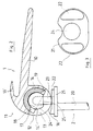
- centrally and posteriorly bicondylar part 11 includes a cavity 15 of which the opening is arranged opposite the notch intercondylar 13 and oriented towards the posterior condyles 16, and in which is arranged a cup 14 having a hemispherical opening 14 '.
- the tibial implant 2 has a rod intramedullary 20 surmounted by a tibial base 21 on which are removably secured by means known per se, two half-plates 22.
- the tibial base 21 Centrally and later, between the two half-plates 22, the tibial base 21 includes a lug 23, not visible in Figure 3, at the end of which is fixed a spherical head 24 which for this purpose has an orifice 25 which can be conical, the spherical head 24 being of a diameter equal to that of the hemispherical cavity 14 'of the cup 14, this diameter possibly varying from 10 to 40 mm.
- femoral 1 and tibial implants 2 After implantation of femoral 1 and tibial implants 2, these are assembled by inserting the spherical head 24 in the hemispherical cavity 14 'of the cup 14.
- spherical heads 24 of 25 different hole depths are available to the surgeon, so that he can choose which one is the better suited to ligament tension.
- the surgeon also has half-shelves 22 thick different allowing, after selection of the spherical head 24, to choose the half-plates 22 whose thickness is the better suited to leave a minimum clearance between the condyles 12 and the half-plates 22.
- the cup 14 has an edge 17 extending it beyond the diameter of the hemispherical cavity 14 ', this edge 17 being hollowed out by two grooves 18 and 19 whose width allows the passage of the lug 23, diametrically opposite opposite the notch intercondylar 13, so as not to limit the flexion and extension movements.
- Such a prosthesis allows the constraints are applied only to the torque formed by the head spherical 24 and the hemispherical cavity 14 ', preventing any lateral play, while movements in the frontal plane are limited to the clearance existing between the condyles 12 and the tibial plates 22, as can be seen in FIG. 4.
Description
- la figure 1 représente une vue en perspective d'une prothèse de l'articulation du genou selon l'invention, en position de semi-flexion.
- la figure 2 représente une vue partielle de profil d'une prothèse selon l'invention dans la même position, avec coupe selon un plan médian de l'implant fémoral.
- la figure 3 représente une vue en plan de l'implant tibial de la même prothèse.
- la figure 4 représente une vue partielle de face de le même prothèse dans la même position de semi-flexion.
Claims (8)
- Prothèse de genou à articulation sphérique, notamment prothèse de remplacement d'une prothèse implantée antérieurement, comprenant d'une part un implant fémoral (1) présentant une partie condylienne (11) dans laquelle est formée une cavité centrale (15) ouverte en regard d'une échancrure intercondylienne (13), et dans laquelle est disposée une cupule (14) présentant une ouverture hémisphérique (14'), et d'autre part un implant tibial (2) comportant une embase tibiale (21) sur laquelle est solidarisé un plateau (22) en matière plastique, un ergot (23) faisant en outre saillie de l'embase tibiale entre les plateaux précités, caractérisée en ce que la cupule (14) contient une tête sphérique (24) dont le diamètre est égal à l'ouverture (14') de la cupule (14), et qui présente un orifice (25) permettant de coiffer l'ergot par ladite tête sphérique.
- Prothèse selon la revendication 1 caractérisée en ce que la cupule (14) est prolongée par des bords (17) dans lesquels sont creusées deux gorges (18, 19), dont la largeur permet le passage de l'ergot (23), diamétralement opposées en regard de l'échancrure intercondylienne (13).
- Prothèse selon la revendication 1 caractérisée en ce que la cupule (14) est à rétention de manière à retenir la tête sphérique (24).
- Prothèse selon l'une quelconque des revendications précédentes caractérisée en ce que la cupule (14) est libre en mouvement dans la cavité (15).
- Prothèse selon l'une quelconque des revendications précédentes caractérisée en ce que la fixation de la tête sphérique (24) sur l'ergot (23) est réalisée par emmanchement conique.
- Prothèse selon l'une quelconque des revendications précédentes caractérisée en ce que le plateau (22) est mobile en rotation et en translation sur l'embase tibiale (21).
- Prothèse selon l'une quelconque des revendications précédentes, caractérisée en ce que le plateau (22) est formé de deux demi-plateaux placés de part et d'autre de l'ergot central (23).
- Prothèse selon l'une quelconque des revendications précédentes, caractérisée en ce que l'implant fémoral (1) comporte une partie trochléenne (13') prolongeant sa partie bicondylienne (11).
Priority Applications (5)
| Application Number | Priority Date | Filing Date | Title |
|---|---|---|---|
| AT93440065T ATE175569T1 (de) | 1993-08-20 | 1993-08-20 | Knieprothese mit kugelgelenk |
| ES93440065T ES2128405T3 (es) | 1993-08-20 | 1993-08-20 | Protesis de rodilla con articulacion esferica. |
| EP93440065A EP0639358B1 (fr) | 1993-08-20 | 1993-08-20 | Prothèse de genou à articulation sphérique |
| DE69323077T DE69323077T2 (de) | 1993-08-20 | 1993-08-20 | Knieprothese mit Kugelgelenk |
| GR990400654T GR3029570T3 (en) | 1993-08-20 | 1999-03-04 | Knee prosthesis with ball joint. |
Applications Claiming Priority (1)
| Application Number | Priority Date | Filing Date | Title |
|---|---|---|---|
| EP93440065A EP0639358B1 (fr) | 1993-08-20 | 1993-08-20 | Prothèse de genou à articulation sphérique |
Publications (2)
| Publication Number | Publication Date |
|---|---|
| EP0639358A1 EP0639358A1 (fr) | 1995-02-22 |
| EP0639358B1 true EP0639358B1 (fr) | 1999-01-13 |
Family
ID=8214808
Family Applications (1)
| Application Number | Title | Priority Date | Filing Date |
|---|---|---|---|
| EP93440065A Expired - Lifetime EP0639358B1 (fr) | 1993-08-20 | 1993-08-20 | Prothèse de genou à articulation sphérique |
Country Status (5)
| Country | Link |
|---|---|
| EP (1) | EP0639358B1 (fr) |
| AT (1) | ATE175569T1 (fr) |
| DE (1) | DE69323077T2 (fr) |
| ES (1) | ES2128405T3 (fr) |
| GR (1) | GR3029570T3 (fr) |
Families Citing this family (7)
| Publication number | Priority date | Publication date | Assignee | Title |
|---|---|---|---|---|
| DE19606462C1 (de) * | 1996-02-21 | 1997-10-16 | Plus Endoprothetik Ag | Kniegelenkendoprothese |
| FR2751204B1 (fr) * | 1996-07-16 | 1999-02-26 | Landanger Camus Sa | Prothese de genou, en particulier prothese de reprise |
| GB9919954D0 (en) * | 1999-08-23 | 1999-10-27 | Walker Peter S | Linked condylar total knee replacement |
| DE102014106012B9 (de) * | 2014-04-29 | 2015-09-17 | Aesculap Ag | Kniegelenkendoprothese |
| DE102015119105A1 (de) | 2015-11-06 | 2017-05-11 | Aesculap Ag | Kniegelenkendoprothese |
| FR3052968B1 (fr) * | 2016-06-22 | 2018-07-27 | Aston Medical | Ensemble prothetique pour l'articulation du genou |
| CN112842631A (zh) * | 2020-12-31 | 2021-05-28 | 上海晟实医疗器械科技有限公司 | 一种3d打印股骨髓内钉全膝关节假体 |
Family Cites Families (6)
| Publication number | Priority date | Publication date | Assignee | Title |
|---|---|---|---|---|
| US3868730A (en) * | 1973-09-24 | 1975-03-04 | Howmedica | Knee or elbow prosthesis |
| US4085466A (en) * | 1974-11-18 | 1978-04-25 | National Research Development Corporation | Prosthetic joint device |
| US4224697A (en) * | 1978-09-08 | 1980-09-30 | Hexcel Corporation | Constrained prosthetic knee |
| GB2088724B (en) * | 1980-12-05 | 1984-03-28 | Attenborough Sheila Marianne | Endoprosthetic bone joint device |
| DE3315401A1 (de) * | 1983-04-28 | 1984-10-31 | Feldmühle AG, 4000 Düsseldorf | Kniegelenkendoprothese |
| DE4102509C2 (de) * | 1991-01-29 | 1996-06-20 | Peter Brehm | Kniegelenkendoprothese |
-
1993
- 1993-08-20 ES ES93440065T patent/ES2128405T3/es not_active Expired - Lifetime
- 1993-08-20 EP EP93440065A patent/EP0639358B1/fr not_active Expired - Lifetime
- 1993-08-20 AT AT93440065T patent/ATE175569T1/de not_active IP Right Cessation
- 1993-08-20 DE DE69323077T patent/DE69323077T2/de not_active Expired - Fee Related
-
1999
- 1999-03-04 GR GR990400654T patent/GR3029570T3/el unknown
Also Published As
| Publication number | Publication date |
|---|---|
| ES2128405T3 (es) | 1999-05-16 |
| DE69323077T2 (de) | 1999-06-17 |
| ATE175569T1 (de) | 1999-01-15 |
| GR3029570T3 (en) | 1999-06-30 |
| DE69323077D1 (de) | 1999-02-25 |
| EP0639358A1 (fr) | 1995-02-22 |
Similar Documents
| Publication | Publication Date | Title |
|---|---|---|
| JP3249062B2 (ja) | 人工膝関節 | |
| EP0890347B1 (fr) | Prothèse de l'articulation du genou | |
| US6162254A (en) | Knee prosthesis | |
| US5458637A (en) | Orthopaedic base component with modular augmentation block | |
| US6080195A (en) | Rotatable and translatable joint prosthesis with posterior stabilization | |
| EP1374805B1 (fr) | Prothèse modulaire de l'articulation du genou | |
| EP1025819B1 (fr) | Prothese totale du genou à insert mobile par rapport à un tenon | |
| US6010534A (en) | Rotatable tibial prosthesis with keyed axial securement | |
| EP0684804B1 (fr) | Prothese totale du genou | |
| EP0950387A1 (fr) | Prothèse de genou | |
| JPH0572824B2 (fr) | ||
| FR2772593A1 (fr) | Implant femoral d'une prothese de genou et ensemble de materiel orthopedique comprenant un tel implant femoral | |
| FR2681240A1 (fr) | Prothese totale de poignet. | |
| GB2336317A (en) | Complete knee joint prosthesis | |
| FR2653992A1 (fr) | Prothese totale du genou a glissement. | |
| FR2740326A1 (fr) | Prothese femoro-patellaire du genou | |
| FR2812541A1 (fr) | Prothese unicompartimentale du genou | |
| EP0567705A1 (fr) | Prothèse totale postéro-stabilisée du genou | |
| EP0639358B1 (fr) | Prothèse de genou à articulation sphérique | |
| FR2721820A1 (fr) | Articulation prothetique de genou, notamment prothese unicompartimentale de genou, ou prothese de la rotule | |
| FR2758456A1 (fr) | Prothese d'articulation du genou dite "postero-stabilisee" | |
| EP0645126A2 (fr) | Prothèse bicondylienne de l'articulation du genou postéro-stabilisée | |
| EP0627202B1 (fr) | Ensemble prothétique pour la réalisation d'une prothèse du genou | |
| FR2793677A1 (fr) | Prothese totale de genou a charniere et manchon de comblement osseux | |
| FR2628316A1 (fr) | Prothese totale du genou |
Legal Events
| Date | Code | Title | Description |
|---|---|---|---|
| PUAI | Public reference made under article 153(3) epc to a published international application that has entered the european phase |
Free format text: ORIGINAL CODE: 0009012 |
|
| AK | Designated contracting states |
Kind code of ref document: A1 Designated state(s): AT BE CH DE DK ES FR GB GR IT LI LU MC NL PT SE SE |
|
| RBV | Designated contracting states (corrected) |
Designated state(s): AT BE CH DE DK ES FR GB GR IT LI LU MC NL PT SE |
|
| RBV | Designated contracting states (corrected) |
Designated state(s): AT BE CH DE DK ES FR GB GR IE IT LI LU MC NL PT SE |
|
| RBV | Designated contracting states (corrected) |
Designated state(s): AT BE CH DE DK ES FR GB GR IT LI LU MC NL PT SE |
|
| 17P | Request for examination filed |
Effective date: 19950724 |
|
| 17Q | First examination report despatched |
Effective date: 19970521 |
|
| GRAG | Despatch of communication of intention to grant |
Free format text: ORIGINAL CODE: EPIDOS AGRA |
|
| GRAG | Despatch of communication of intention to grant |
Free format text: ORIGINAL CODE: EPIDOS AGRA |
|
| GRAH | Despatch of communication of intention to grant a patent |
Free format text: ORIGINAL CODE: EPIDOS IGRA |
|
| GRAH | Despatch of communication of intention to grant a patent |
Free format text: ORIGINAL CODE: EPIDOS IGRA |
|
| GRAA | (expected) grant |
Free format text: ORIGINAL CODE: 0009210 |
|
| AK | Designated contracting states |
Kind code of ref document: B1 Designated state(s): AT BE CH DE DK ES FR GB GR IT LI LU MC NL PT SE |
|
| PG25 | Lapsed in a contracting state [announced via postgrant information from national office to epo] |
Ref country code: SE Free format text: THE PATENT HAS BEEN ANNULLED BY A DECISION OF A NATIONAL AUTHORITY Effective date: 19990113 |
|
| REF | Corresponds to: |
Ref document number: 175569 Country of ref document: AT Date of ref document: 19990115 Kind code of ref document: T |
|
| REG | Reference to a national code |
Ref country code: CH Ref legal event code: EP |
|
| REF | Corresponds to: |
Ref document number: 69323077 Country of ref document: DE Date of ref document: 19990225 |
|
| GBT | Gb: translation of ep patent filed (gb section 77(6)(a)/1977) |
Effective date: 19990211 |
|
| ITF | It: translation for a ep patent filed |
Owner name: INVENTION S.N.C. |
|
| PG25 | Lapsed in a contracting state [announced via postgrant information from national office to epo] |
Ref country code: DK Free format text: LAPSE BECAUSE OF FAILURE TO SUBMIT A TRANSLATION OF THE DESCRIPTION OR TO PAY THE FEE WITHIN THE PRESCRIBED TIME-LIMIT Effective date: 19990413 |
|
| REG | Reference to a national code |
Ref country code: ES Ref legal event code: FG2A Ref document number: 2128405 Country of ref document: ES Kind code of ref document: T3 |
|
| REG | Reference to a national code |
Ref country code: PT Ref legal event code: SC4A Free format text: AVAILABILITY OF NATIONAL TRANSLATION Effective date: 19990315 |
|
| PLBE | No opposition filed within time limit |
Free format text: ORIGINAL CODE: 0009261 |
|
| STAA | Information on the status of an ep patent application or granted ep patent |
Free format text: STATUS: NO OPPOSITION FILED WITHIN TIME LIMIT |
|
| 26N | No opposition filed | ||
| REG | Reference to a national code |
Ref country code: GB Ref legal event code: IF02 |
|
| PGFP | Annual fee paid to national office [announced via postgrant information from national office to epo] |
Ref country code: CH Payment date: 20040712 Year of fee payment: 12 |
|
| PGFP | Annual fee paid to national office [announced via postgrant information from national office to epo] |
Ref country code: MC Payment date: 20040713 Year of fee payment: 12 |
|
| PGFP | Annual fee paid to national office [announced via postgrant information from national office to epo] |
Ref country code: AT Payment date: 20040716 Year of fee payment: 12 |
|
| PGFP | Annual fee paid to national office [announced via postgrant information from national office to epo] |
Ref country code: NL Payment date: 20040722 Year of fee payment: 12 |
|
| PGFP | Annual fee paid to national office [announced via postgrant information from national office to epo] |
Ref country code: GR Payment date: 20040727 Year of fee payment: 12 |
|
| PGFP | Annual fee paid to national office [announced via postgrant information from national office to epo] |
Ref country code: GB Payment date: 20040803 Year of fee payment: 12 |
|
| PGFP | Annual fee paid to national office [announced via postgrant information from national office to epo] |
Ref country code: DE Payment date: 20040806 Year of fee payment: 12 |
|
| PGFP | Annual fee paid to national office [announced via postgrant information from national office to epo] |
Ref country code: ES Payment date: 20040816 Year of fee payment: 12 |
|
| PGFP | Annual fee paid to national office [announced via postgrant information from national office to epo] |
Ref country code: FR Payment date: 20040817 Year of fee payment: 12 |
|
| PGFP | Annual fee paid to national office [announced via postgrant information from national office to epo] |
Ref country code: PT Payment date: 20040819 Year of fee payment: 12 |
|
| PGFP | Annual fee paid to national office [announced via postgrant information from national office to epo] |
Ref country code: BE Payment date: 20040901 Year of fee payment: 12 |
|
| PGFP | Annual fee paid to national office [announced via postgrant information from national office to epo] |
Ref country code: LU Payment date: 20041015 Year of fee payment: 12 |
|
| PG25 | Lapsed in a contracting state [announced via postgrant information from national office to epo] |
Ref country code: LU Free format text: LAPSE BECAUSE OF NON-PAYMENT OF DUE FEES Effective date: 20050820 Ref country code: IT Free format text: LAPSE BECAUSE OF NON-PAYMENT OF DUE FEES;WARNING: LAPSES OF ITALIAN PATENTS WITH EFFECTIVE DATE BEFORE 2007 MAY HAVE OCCURRED AT ANY TIME BEFORE 2007. THE CORRECT EFFECTIVE DATE MAY BE DIFFERENT FROM THE ONE RECORDED. Effective date: 20050820 Ref country code: GB Free format text: LAPSE BECAUSE OF NON-PAYMENT OF DUE FEES Effective date: 20050820 Ref country code: AT Free format text: LAPSE BECAUSE OF NON-PAYMENT OF DUE FEES Effective date: 20050820 |
|
| PG25 | Lapsed in a contracting state [announced via postgrant information from national office to epo] |
Ref country code: ES Free format text: LAPSE BECAUSE OF NON-PAYMENT OF DUE FEES Effective date: 20050822 |
|
| PG25 | Lapsed in a contracting state [announced via postgrant information from national office to epo] |
Ref country code: MC Free format text: LAPSE BECAUSE OF NON-PAYMENT OF DUE FEES Effective date: 20050831 Ref country code: LI Free format text: LAPSE BECAUSE OF NON-PAYMENT OF DUE FEES Effective date: 20050831 Ref country code: CH Free format text: LAPSE BECAUSE OF NON-PAYMENT OF DUE FEES Effective date: 20050831 Ref country code: BE Free format text: LAPSE BECAUSE OF NON-PAYMENT OF DUE FEES Effective date: 20050831 |
|
| PG25 | Lapsed in a contracting state [announced via postgrant information from national office to epo] |
Ref country code: PT Free format text: LAPSE BECAUSE OF NON-PAYMENT OF DUE FEES Effective date: 20060220 |
|
| PG25 | Lapsed in a contracting state [announced via postgrant information from national office to epo] |
Ref country code: NL Free format text: LAPSE BECAUSE OF NON-PAYMENT OF DUE FEES Effective date: 20060301 Ref country code: DE Free format text: LAPSE BECAUSE OF NON-PAYMENT OF DUE FEES Effective date: 20060301 |
|
| PG25 | Lapsed in a contracting state [announced via postgrant information from national office to epo] |
Ref country code: GR Free format text: LAPSE BECAUSE OF NON-PAYMENT OF DUE FEES Effective date: 20060302 |
|
| REG | Reference to a national code |
Ref country code: CH Ref legal event code: PL |
|
| GBPC | Gb: european patent ceased through non-payment of renewal fee |
Effective date: 20050820 |
|
| PG25 | Lapsed in a contracting state [announced via postgrant information from national office to epo] |
Ref country code: FR Free format text: LAPSE BECAUSE OF NON-PAYMENT OF DUE FEES Effective date: 20060428 |
|
| NLV4 | Nl: lapsed or anulled due to non-payment of the annual fee |
Effective date: 20060301 |
|
| REG | Reference to a national code |
Ref country code: FR Ref legal event code: ST Effective date: 20060428 |
|
| REG | Reference to a national code |
Ref country code: ES Ref legal event code: FD2A Effective date: 20050822 |
|
| BERE | Be: lapsed |
Owner name: SOC. CIVILE *ESSOR Effective date: 20050831 |