EP0638682B1 - Embroidering machine with shuttles and yarn cutting device - Google Patents
Embroidering machine with shuttles and yarn cutting device Download PDFInfo
- Publication number
- EP0638682B1 EP0638682B1 EP94810462A EP94810462A EP0638682B1 EP 0638682 B1 EP0638682 B1 EP 0638682B1 EP 94810462 A EP94810462 A EP 94810462A EP 94810462 A EP94810462 A EP 94810462A EP 0638682 B1 EP0638682 B1 EP 0638682B1
- Authority
- EP
- European Patent Office
- Prior art keywords
- embroidering machine
- knife
- thread
- rails
- lever
- Prior art date
- Legal status (The legal status is an assumption and is not a legal conclusion. Google has not performed a legal analysis and makes no representation as to the accuracy of the status listed.)
- Expired - Lifetime
Links
Images

Classifications
-
- D—TEXTILES; PAPER
- D05—SEWING; EMBROIDERING; TUFTING
- D05C—EMBROIDERING; TUFTING
- D05C11/00—Devices for guiding, feeding, handling, or treating the threads in embroidering machines; Machine needles; Operating or control mechanisms therefor
- D05C11/20—Arrangements for cutting the needle or lower threads
Definitions
- the present invention relates to a shuttle embroidery machine with shuttle tracks arranged on a profile, which are delimited on the fabric side by a stitch plate, and a thread cutting device for the rear thread with a knife, which can be positioned by a mechanism in front of the stitch plate for a cutting process.
- the Swiss patent specification CH 660 608 discloses an embroidery machine in which a coupling is provided at each individual embroidery point in the drive train for the driver rod for the switching on and off of the respective embroidery point which can be influenced independently.
- the thread is behind the needle plate automatically cut by a thread cutter.
- This device has the disadvantage that a separate drive is assigned to each individual thread clamping and cutting device and this requires a large amount of space. For this reason, this device cannot be used on every shuttle embroidery machine.
- the thread previously clamped for cutting can be released again after cutting, so that damage to the latter can occur during further operation.
- a thread clamping and cutting device for the back or under thread of an embroidery machine is disclosed, which is arranged in the area of the stitch hole and also cuts the thread behind the stitch plate.
- the clamping gap of the thread clamping device is arranged in alignment with the cutting device.
- This device is characterized in that an intermediate plate with slot-shaped recesses is mounted on the throat plate, into which a guide part can be inserted.
- the guide part has an inner recess in which an actuating slide is slidably guided.
- the actuating slide itself has a U-shaped profile, in which the guide part engages with a projection, so that the actuating slide is guided.
- the actuating slide is screwed to an actuating rod which can be moved back and forth by a sliding drive.
- Two keyhole-shaped recesses are aligned in the U-profile, which are at the height of the stitch hole when embroidering.
- the lower boundary of the front keyhole-shaped recess is designed as a cutting edge.
- the counter knife is clipped in place in the guide part above the tap hole.
- the clamping gap is formed by a resiliently mounted clamping finger in the guide part and a counter-clamping piece inserted in the guide part. Due to the construction described, the thread is first clamped in the clamping gap during the cutting process and then cut.
- Another advantage is that the thread remains clamped in the clamping gap even after the actuating slide has been retracted, and only then is relieved by sufficient tension from the nip when re-stitching.
- the cutting and clamping device described also clamps the thread after the cutting process and is extremely space-saving.
- the cutting and clamping device is relatively complex, complicated and therefore expensive.
- the sliding mechanism is contaminated by external influences or by abrasion and this can lead to longer downtimes.
- GB-A-12 185 discloses a thread clamping and cutting device for the rear thread of a shuttle embroidery machine which is arranged during embroidery below the carrier rail which carries the shuttle and the associated drive.
- This device has a shaft which is rotatable and displaceable in the longitudinal direction.
- a crank is arranged on the shaft, which carries a rail which can extend along the entire embroidery machine.
- a plate is also attached to the rail, which has cutting surfaces on the upper edge.
- the carrier rail with the shuttle is pulled back a little to create a space between the embroidered fabric and the needle plate. Then the shaft of the thread clamping and cutting device is shifted and rotated in the longitudinal direction, whereby the plate is pivoted in front of the needle plate and strikes it.
- the plate During the upward movement, the plate hits the rear thread, clamps it onto the needle plate and cuts it off.
- the thread is clamped during the cutting process and remains clamped even after cutting so that it can be sewn on again.
- the device described has the disadvantage that it is not possible to cut the rear thread without prior clamping, since otherwise the thread would be pulled out of the shuttle by the simple knife movement.
- the needle hole cannot act as a counter knife, since the edges of the needle hole must be rounded in order to avoid inadvertent chafing or cutting off of the rear thread during embroidery.
- the cutting device should be robust, easily accessible, easy to service and insensitive to dirt. It would also be an advantage if embroidery or sewing machines already in use could also be inexpensively retrofitted with the cutting device.
- the knife has a guide element and that the mechanism ensures a relative movement of the knife and guide element for cutting the thread.
- the knife and the guide element virtually perform a scissor movement when cutting, i.e. the cutting surface of the knife crosses or intersects with an edge of the guide element.
- This type of cutting movement of the knife and guide element means that the thread is not stressed during cutting and there is no danger that it would be pulled out of the shuttle. For this reason, thread clamping can be dispensed with, e.g. is necessary if the thread is to be cut off at the tap hole (see GB-A-12 185). In contrast to DE-OS-2 065 264, no gripper is needed to grasp the thread to be cut.
- the solution according to the invention is therefore simple, robust and inexpensive.
- Another advantage is that the thread cutting device works independently, i.e. that these e.g. is not coupled with the decommissioning of boats as described in CH 660 608. As a result, the rear thread can be cut off without the associated shuttle being shut down for further operation at the same time. Moving the knife enables the thread to be cut in front of the stitch plate and close to the embroidery site.
- An edge of the guide element is expediently designed as a cutting edge, which can interact with the cutting edge of the knife. Because the thread is cut by two intersecting cutting surfaces, thin ones can also be cut Threads of whatever material are reliably cut.
- the knives and the guide elements are advantageously detachably attached to rails. This is particularly advantageous because the actuating mechanism then only has to ensure a relative movement of the rails. As a result, a large number of knives can be actuated with just one drive, which considerably simplifies the construction. It is also advantageous if the knives and the guide elements are formed in blocks on a knife rail or. are combined into a guide plate. These can be changed quickly if necessary, for example to sharpen the cutting edges.
- the knives are expediently connected to the mechanism in such a way that when the same is actuated, both a displacement of the knives along at least one axis and a relative movement of the same results.
- This can e.g. by means of a suitable eccentric device or a lever arrangement which positions the knives in front of the throat plate and at the same time ensures a scissor movement of the knives.
- the cutting device can be arranged below the angle profile or at another location on the embroidery machine.
- the mechanism advantageously has at least one pivotable lever which connects the rails in an articulated manner.
- the two rails can be moved apart like scissors by the lever.
- Another advantageous construction provides that the rails are connected to one another by means of two levers arranged one behind the other, a lever which is articulated on one rail and an angle lever which is articulated at its angle on the other rail.
- the angle lever can have two arms of different lengths, so that a large lever effect can be generated.
- the actuating mechanism advantageously has a drive shaft which is connected in a rotationally fixed manner to a further lever. The free end of this lever is articulated to a lever already described above, which is required for the relative movement of the two rails.
- the rotation of the drive shaft can a vertical displacement of the rails can be effected at the same time.
- the drive shaft in order to generate a feed movement, is connected in a rotationally fixed manner to a link having a curve, the link interacting with a stationary part.
- a translatory movement of the shaft can be generated simultaneously by a rotary movement.
- the knife can thus be moved when cutting onto the fabric stretched on the creel, and the thread can be cut off directly at the embroidery site.
- the backdrop is advantageously cylindrical and has a curved channel milled into the lateral surface. A stationary bolt can protrude into this channel, so that when the link is rotated it is moved in the longitudinal direction.
- the knife expediently has a hook-shaped cutting edge which cooperates with the upper edge of the guide plate designed as a counter knife during thread cutting. Thanks to the two cutting edges, the thread can be cut cleanly.
- the knife has a straight cutting edge which is at an angle to the upper edge of the guide part.
- the angle between the cutting edge and the upper edge of the guide plate can be between approximately 4 and 45 °, preferably approximately 5 to 25 °.
- the thread to be cut can be easily positioned under the cutting edge and the result is a scissor movement that promotes cutting.
- Another advantage is that the deflection of the knife needs to be less than e.g. when using hook-shaped cutting edges.
- Guides are preferably provided on the guide plate, which connect the knife bar and the guide plate. This ensures tight guidance of the knives on the guide plates.
- the knives and the guide plates can be pretensioned, ie slightly curved. This feature ensures that the cutting edge of the knife the upper edge of the guide plate, which is designed as a counter knife, can interact optimally.
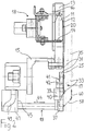
- Figures 1 and 2 show a thread cutting device 17 and upwardly projecting shuttle webs 13 of a shuttle embroidery machine.
- the shuttle tracks 13 are screwed to an angular profile 15, the so-called Stöcklilineal.
- the shuttle lanes 13 are each delimited by the throat plate 12.
- the shuttle 11 move up and down during the embroidery process.
- the boats 11 are held or driven by the driver nails 14, 16, which are arranged on the movable oscillating beam 18.
- the shuttle 11 are looped through the upper or front thread carried out, which is brought by means of the embroidery needle through the tap hole 20 in the shuttle 13.
- the thread cutting device 17 already mentioned, which is shown in FIG. 1 in two different positions.
- the representation at the edge of the drawing shows the thread cutting device 17 in the rest position; the other illustration shows the thread cutting device 17 in the cutting position.
- the cutting position is shown in dashed lines in FIG.
- the cutting device can be displaced along two axes (arrows 58, 60).
- the thread cutting device 17 is in the rest position approximately in the plane of the needle plate 12.
- the device in front of the needle plate 12 or. positioned on the embroidered fabric so that the thread can be cut as close as possible to the embroidery site.
- the thread cutting device 17 comprises an actuating mechanism 19 and a plurality of knives 21 arranged at a distance from the stitch holes 20.
- a plurality of knives 21 can be formed on a single sheet and form a knife rail 31 (FIG. 1).
- the knives 21 are guided by a guide plate 25.
- the guide plate 25 has punched-out ears 27 projecting from the surface, by means of which the shank of the knives 21 is guided in each case.
- a large number of knife rails 31 and guide plates 25 each work in pairs and are detachably fastened to rails 33, 35.
- the rails 33, 35 can be moved relative to one another by the mechanism 19 and can be positioned in front of the throat plate 12.
- the knife rails 31 and guide plates 25 shown can be produced simply, for example by punching them out of a metal sheet. They advantageously consist of a thin spring steel sheet.
- the knives 21 run parallel to the shuttle tracks 13 and have a hook-shaped cutting edge 23.
- the upper edge 29 of the guide element 25 is also designed as a cutting edge, which is each provided with a knife 21 cooperates.
- the knife rails 31 and / or the guide plates 25 are expediently prestressed against one another, ie are slightly concave. This ensures that the cutting edges 23, 29 run closely together.
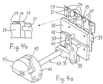
- the knives 21 ′ according to FIG. 4 have approximately straight cutting edges 24 instead of the hook-shaped cutting edges 23, which are at a certain angle to the upper edges of the guide plates 25.
- This design of the cutting edges 24 has the advantage that the thread to be cut can be positioned particularly easily under the cutting edge 24. It has proven to be advantageous if the cutting edges 24 are at an angle between approximately 5 and 25 ° to the upper edge 29 of the guide plate 25.
- the knives 21, 21 ' can be positioned in front of the throat plate 12 for cutting.
- the structural details of a preferred embodiment, which can cause the displacement and the actual cutting movement of the knives, are discussed in more detail below.
- the rails 33, 35 carrying the knife rails 31 and the guide plates 25 must be moved relative to one another in such a way that the cutting edges of the knives 21 and the upper edge 29 of the guide plate 25 can overlap.
- the knife rail 31 is releasably attached to the rail 35.
- the guide plate 25, however, is releasably attached to the rail 33.
- the rails 33, 35 are articulated to one another with two levers 39, 41.
- the lever 41 is articulated at one end to a pin 42 arranged on the rail 35.
- the lever 39 is designed as an angle lever and is articulated at an angle on a pin 40 of the rail 33.
- a pivoting of the angle lever 39 has the effect that the two rails 33, 35, which are perpendicular to their longitudinal extension (not shown), are deflected relative to one another (FIG. 1).
- a drive shaft 43 is provided, which is connected in a rotationally fixed manner to a lever 37.
- the lever 37 is articulated on the angle lever 39 at the other end.
- the guided rails 33, 35 are moved upward, as shown in FIG.
- This arrangement therefore has the advantage that not only is a relative movement of the rails 33, 35 produced by rotating the drive shaft 43, but they are simultaneously displaced a certain distance.
- the rails 33, 35 can be raised to approximately the height of the tap hole 20 (FIG. 1).
- a cylindrical link 45 is provided in order to move the cutting device 17, which in a preferred embodiment is in the plane of the throat plate 12 (FIG. 2) or behind it, in front of the throat plate 12, a cylindrical link 45 is provided. This is firmly connected to the drive shaft 43. A curved channel 49 is milled out in the lateral surface 47 of the backdrop 45. A fixed pin (not shown), which can be arranged on the profile 15, engages in this channel 49.
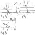
- FIG. 3 Further possible designs for generating the deflection of the rails 33, 35 and the relative movement thereof are shown schematically in FIG. 3.
- a straight lever 55 is articulated on the rail 33 approximately in the middle.
- One end of the lever 55 is guided in a slot 59 in the rail 35, the other end of the lever 55 is articulated on a lever 57.
- the rails 33, 35 are inevitably shifted upward.
- the rails 33, 35 perform a scissor movement (FIG. 3b).
- the rails 33, 35 are guided by suitable means in such a way that they can only be displaced perpendicularly to their longitudinal extent.
- 3 c shows a further exemplary embodiment for generating the deflection of the rails 33, 35 and the cutting movement.
- the lever 55 has a pin approximately in the middle, which is slidably guided in a slot 59 'in the rail 33. Furthermore, one end of the lever 55 is articulated on the rail 35, the other end on the lever 57. Analogously to the example of FIGS. 3 a, b, the rails 33, 35 can be deflected by pivoting the lever 57 and moved relative to one another.
- the thread cutting works as follows: When the shaft 43 is rotated by drive means (not shown in more detail), the entire drive shaft 43 moves with the rails 33, 35 as a function of the curve 49 of the link 45 along its longitudinal axis (FIG. 1: arrow 44). At the same time, the rails 33, 35 are moved up and apart due to the lever arrangement 37, 39, 41. The movement of the rails 33, 35 takes place along the arrows 58, 60 (FIG. 2). The last part of the movement is only in one direction (vertical). During this last part of the movement, the rails 33, 35 move apart, so that the cutting edges 23 of the knives 21 are moved beyond the upper edge 29 of the guide plate 25, i.e.
- Figure 2 position shown in dashed lines.
- the knife 21 is located in front of the stitch plate 12 in the area of the stitch hole 20.
- the gate with the stretched fabric is then moved so that the thread, which extends from the last embroidery point through the stitch hole 20 to the boat, comes to rest under the cutting edge 23.
- the link 45 is turned back until the cutting edges 23 and the edge 29 intersect and cut the thread (Fig. 2: movement of the rails against arrow 60). This cutting movement can be repeated by rotating the shaft 43 back and forth two or three times. This can ensure that all threads are cut.
- the length of the thread to be cut can be selected so that it can just be re-stitched on, but after the stitching there is no annoying thread at the new embroidery site.
- This has the advantage of being an additional one Device for clamping the thread, as mentioned, for example, in the writings cited at the beginning, can be dispensed with.
Abstract
Description
Die vorliegende Erfindung betrifft eine Schiffchenstickmaschine mit an einem Profil angeordneten Schiffchenbahnen, welche stoffseitig durch eine Stichplatte begrenzt sind, und einer Fadenschneideinrichtung für den Hinterfaden mit einem Messer, das für einen Schneidvorgang durch einen Mechanismus vor die Stichplatte positionierbar ist.The present invention relates to a shuttle embroidery machine with shuttle tracks arranged on a profile, which are delimited on the fabric side by a stitch plate, and a thread cutting device for the rear thread with a knife, which can be positioned by a mechanism in front of the stitch plate for a cutting process.
Beim Sticken müssen bei einem Farb- oder Rapportwechsel die Fäden abgeschnitten werden. Lange Zeit geschah dies, insbesondere bei Schiffchenstickmaschinen, manuell, was natürlich sehr arbeitsintensiv und teuer ist. In den letzten Jahren sind dann Stickmaschinen bekannt geworden, die den Hinter- oder Unterfaden automatisch abschneiden können. Bei der Realisierung einer automatischen Fadenschneideinrichtung stellt sich zunächst einmal das Problem, dass der zur Verfügung stehende Platz für eine Fadenschneideinrichtung bei Stickmaschinen, insbesondere bei grossen Schiffchenstickmaschinen, äusserst knapp ist. Dazu kommt, dass beim Schneiden eines Fadens mit einer einfachen Klingenbewegung der Faden zuerst geklemmt werden muss, damit dieser nicht aus dem Schiffchen herausgezogen werden kann. Ausserdem ist es ein Erfordernis, dass die Fadenschneideinrichtung die Fäden möglichst nahe an der Stickstelle abschneidet. Ansonsten würde das Stickbild an der Rückseite der Textilie beeinträchtig. In der Praxis sollte eine Fadenschneideinrichtung ausserdem möglichst wartungsfreundlich und robust sein, nicht zuletzt deswegen, weil die Stickmaschinen heutzutage vor allem in weniger industrialisierten Ländern zum Einsatz kommen. Die Wartung sollte von den dortigen Betreibern der Maschinen mühelos selbst vorgenommen werden können.When embroidering, the threads must be cut when changing color or repeat. For a long time, especially with shuttle embroidery machines, this was done manually, which of course is very labor intensive and expensive. In recent years, embroidery machines have become known that can automatically cut the back or bobbin thread. When implementing an automatic thread cutting device, the problem arises first of all that the space available for a thread cutting device in embroidery machines, in particular in large shuttle embroidery machines, is extremely scarce. In addition, when cutting a thread with a simple blade movement, the thread must first be clamped so that it cannot be pulled out of the shuttle. In addition, it is a requirement that the thread cutting device cuts the threads as close as possible to the embroidery site. Otherwise the embroidery pattern on the back of the textile would be impaired. In practice, a thread cutting device should also be as easy to maintain and robust as possible, not least because the embroidery machines are used today mainly in less industrialized countries. Maintenance should be effortlessly carried out by the machine operators there themselves.
In der schweizerischen Patentschrift CH 660 608 wird eine Stickmaschine offenbart, bei welcher an jeder einzelnen Stickstelle im Antriebsstrang zur Treiberstange eine Kupplung für das unabhängig beeinflussbare An- bzw. Abschalten der jeweiligen Stickstelle vorgesehen ist. Beim Stillsetzen der jeweiligen Stickstelle wird der Faden hinter der Stichplatte selbsttätig durch einen Fadenabschneider abgeschnitten. Diese Vorrichtung hat den Nachteil, dass jeder einzelnen Fadenklemm- und Schneideinrichtung ein eigener Antrieb zugeordnet ist und dafür ein grosser Platzbedarf erforderlich ist. Aus diesem Grund lässt sich diese Einrichtung nicht an jeder Schiffchenstickmaschine einsetzen. Ausserdem kann der zum Schneiden vorgängig geklemmte Faden nach erfolgtem Abschneiden wieder freikommen, sodass im weiteren Betrieb eine Beschädigung desselben auftreten kann.The Swiss patent specification CH 660 608 discloses an embroidery machine in which a coupling is provided at each individual embroidery point in the drive train for the driver rod for the switching on and off of the respective embroidery point which can be influenced independently. When the respective embroidery site is stopped, the thread is behind the needle plate automatically cut by a thread cutter. This device has the disadvantage that a separate drive is assigned to each individual thread clamping and cutting device and this requires a large amount of space. For this reason, this device cannot be used on every shuttle embroidery machine. In addition, the thread previously clamped for cutting can be released again after cutting, so that damage to the latter can occur during further operation.
Ein weiterer Lösungsansatz wird in EP 0 541 923 vorgestellt. Dort wird eine Fadenklemm- und Schneideinrichtung für den Hinter- oder Unterfaden einer Stickmaschine offenbart, die im Bereich des Stichloches angeordnet ist und den Faden ebenfalls hinter der Stichplatte schneidet. Der Klemmspalt der Fadenklemmeinrichtung ist dabei fluchtend mit der Schneidvorrichtung angeordnet. Diese Einrichtung ist dadurch charakterisiert, dass an der Stichplatte eine Zwischenplatte mit langlochförmigen Ausnehmungen montiert ist, in welche ein Führungsteil eingeschoben werden kann. Der Führungsteil hat eine innere Ausnehmung, in welcher ein Betätigungsschieber verschiebbar geführt ist. Der Betätigungsschieber selbst weist ein U-förmiges Profil auf, in welches das Führungsteil mit einem Ansatz eingreift, sodass der Betätigungsschieber geführt ist. Der Betätigungsschieber ist an eine Betätigungsstange festgeschraubt, die durch einen Verschiebeantrieb hin- und herbewegt werden kann. Im U-Profil sind zwei schlüssellochförmige Ausnehmungen fluchtend angeordnet, welche beim Sticken sich in der Höhe des Stichloches befinden. Die untere Begrenzung der vorderen schlüssellochförmigen Ausnehmung ist dabei als Schneidkante ausgebildet. Das Gegenmesser ist im Führungsteil oberhalb des Stichloches ortsfest festgeclipst. Der Klemmspalt wird durch einen federnd im Führungsteil gelagerten Klemmfinger und ein im Führungsteil eingelegtes Gegenklemmstück gebildet. Durch die beschriebene Konstruktionsweise wird der Faden beim Schneidvorgang zuerst im Klemmspalt geklemmt und dann geschnitten. Als weiterer Vorteil gilt, dass der Faden auch nach dem Rückzug des Betätigungsschieber im Klemmspalt festgeklemmt bleibt und erst beim Wiederansticken durch ausreichenden Zug aus dem Klemmspalt gelöst wird. Die beschriebene Schneid- und Klemmvorrichtung klemmt den Faden auch nach dem Schneidvorgang und ist äusserst platzsparend. Nachteilig ist jedoch, dass die Schneid- und Klemmvorrichtung relativ aufwendig, kompliziert und damit teuer ist. Auch besteht die Gefahr, dass der Verschiebemechanismus durch äussere Einflüsse oder durch Abrieb verschmutzt wird und es so zu längeren Stillstandzeitzen kommen kann.Another approach is presented in
In der GB-A-12 185 (A.D. 1910) wird eine Fadenklemm- und Schneideinrichtung für den Hinterfaden einer Schiffchenstickmaschine offenbart, welche während des Stickens unterhalb der Tragschiene angeordnet ist, welche die Schiffchen und den dazugehörigen Antrieb trägt. Diese Einrichtung besitzt eine Welle, welche drehbar und in der Längsrichtung verschiebbar ist. An der Welle ist eine Kurbel angeordnet, die eine Schiene trägt, welche sich entlang der gesamten Stickmaschine erstrecken kann. An der Schiene ist weiter eine Platte befestigt, welche an der oberen Kante Schneidflächen aufweist. Zum Schneiden des Hinterfadens wird die Tragschiene mit den Schiffchen etwas zurückgezogen, um einen Zwischenraum zwischen dem bestickten Stoff und der Stichplatte zu schaffen. Dann wird die Welle der Fadenklemm- und Schneideinrichtung in Längsrichtung verschoben und gedreht, wodurch die Platte vor die Stichplatte geschwenkt wird und an dieser anschlägt. Bei der Aufwärtsbewegung trifft die Platte auf den Hinterfaden, klemmt diesen an der Stichplatte ein und schneidet diesen ab. Das Besondere an dieser Einrichtung ist, dass beim Schneidvorgang der Faden geklemmt wird und auch nach dem Schneiden geklemmt bleibt, sodass wieder angestickt werden kann. Die beschriebene Einrichtung hat allerdings den Nachteil, dass ein Schneiden des Hinterfadens ohne vorgängiges Klemmen gar nicht möglich ist, da der Faden sonst durch die einfache Messerbewegung aus dem Schiffchen herausgezogen würde. Das Nadelloch kann dabei nicht als Gegenmesser fungieren, da die Kanten desselben gerundet sein müssen, um ein unbeabsichtigtes Abscheuern oder Abschneiden der Hinterfadens während des Stickens zu vermeiden.GB-A-12 185 (AD 1910) discloses a thread clamping and cutting device for the rear thread of a shuttle embroidery machine which is arranged during embroidery below the carrier rail which carries the shuttle and the associated drive. This device has a shaft which is rotatable and displaceable in the longitudinal direction. A crank is arranged on the shaft, which carries a rail which can extend along the entire embroidery machine. A plate is also attached to the rail, which has cutting surfaces on the upper edge. To cut the rear thread, the carrier rail with the shuttle is pulled back a little to create a space between the embroidered fabric and the needle plate. Then the shaft of the thread clamping and cutting device is shifted and rotated in the longitudinal direction, whereby the plate is pivoted in front of the needle plate and strikes it. During the upward movement, the plate hits the rear thread, clamps it onto the needle plate and cuts it off. What is special about this device is that the thread is clamped during the cutting process and remains clamped even after cutting so that it can be sewn on again. However, the device described has the disadvantage that it is not possible to cut the rear thread without prior clamping, since otherwise the thread would be pulled out of the shuttle by the simple knife movement. The needle hole cannot act as a counter knife, since the edges of the needle hole must be rounded in order to avoid inadvertent chafing or cutting off of the rear thread during embroidery.
Es ist Aufgabe der vorliegenden Erfindung, eine Stickmaschine, insbesondere eine Schiffchenstickmaschine, bereitszustellen, bei der die eingangs erwähnten Nachteile weitgehend vermieden werden können und der Faden möglichst direkt an der Stickstelle abgeschnitten werden kann. Die Schneideinrichtung sollte dabei robust, leicht zugänglich und servicefreundlich sowie verschmutzungsunempfindlich sein. Dabei wäre es auch von Vorteil, wenn bereits im Einsatz stehende Stick- oder Nähmaschinen ebenfalls kostengünstig mit der Schneideinrichtung nachgerüstet werden könnten.It is an object of the present invention to provide an embroidery machine, in particular a shuttle embroidery machine, in which the disadvantages mentioned at the outset can be largely avoided and the thread can be cut off as directly as possible at the embroidery site. The cutting device should be robust, easily accessible, easy to service and insensitive to dirt. It would also be an advantage if embroidery or sewing machines already in use could also be inexpensively retrofitted with the cutting device.
Erfindungsgemäss wird dies dadurch erreicht, dass das Messer ein Führungselement besitzt und dass zum Schneiden des Fadens der Mechanismus für eine Relativbewegung von Messer und Führungselement sorgt. Das Messer und das Führungselement führen beim Schneiden quasi eine Scherenbewegung aus, d.h. die Schneidfläche des Messers kreuzt resp. überschneidet sich mit einer Kante des Führungselementes. Durch diese Art der Schneidbewegung von Messer und Führungselement wird der Faden beim Schneiden nicht belastet und es besteht keine Gefahr, dass dieser aus dem Schiffchen herausgezogen würde. Aus diesem Grund kann auf ein Fadenklemmen verzichtet werden, wie es z.B. nötig ist, wenn der Faden beim Stichloch abgeschnitten werden soll (s. GB-A-12 185). Im Unterschied zur DE-OS-2 065 264 braucht es auch keinen Greifer zum Fassen des abzuschneidenden Fadens. Die erfindungsgemässe Lösung ist daher einfach, robust und kostengünstig. Ein weiterer Vorteil ist, dass die Fadenschneideinrichtung unabhängig funktioniert, d.h. dass diese z.B. nicht wie in der CH 660 608 beschrieben mit der Schiffchenstillegung gekoppelt ist. Dadurch kann der Hinterfaden abgeschnitten werden, ohne dass gleichzeitig das zugehörige Schiffchen für den weiteren Betrieb stillgelegt wird. Das Verschieben des Messers ermöglicht das Schneiden des Fadens vor der Stichplatte und nahe an der Stickstelle.According to the invention, this is achieved in that the knife has a guide element and that the mechanism ensures a relative movement of the knife and guide element for cutting the thread. The knife and the guide element virtually perform a scissor movement when cutting, i.e. the cutting surface of the knife crosses or intersects with an edge of the guide element. This type of cutting movement of the knife and guide element means that the thread is not stressed during cutting and there is no danger that it would be pulled out of the shuttle. For this reason, thread clamping can be dispensed with, e.g. is necessary if the thread is to be cut off at the tap hole (see GB-A-12 185). In contrast to DE-OS-2 065 264, no gripper is needed to grasp the thread to be cut. The solution according to the invention is therefore simple, robust and inexpensive. Another advantage is that the thread cutting device works independently, i.e. that these e.g. is not coupled with the decommissioning of boats as described in CH 660 608. As a result, the rear thread can be cut off without the associated shuttle being shut down for further operation at the same time. Moving the knife enables the thread to be cut in front of the stitch plate and close to the embroidery site.
Zweckmässigerweise ist eine Kante des Führungselements als Schneide ausgebildet, welche mit der Schneide des Messers zusammenwirken kann. Dadurch, dass der Faden durch zwei sich kreuzende Schneidflächen geschnitten wird, können auch dünne Fäden gleich welchen Materials zuverlässig durchtrennt werden. Vorteilhaft sind die Messer und die Führungselemente an Schienen lösbar befestigt. Dies ist besonders vorteilhaft, weil der Betätigungsmechanismus dann lediglich für eine Relativbewegung der Schienen sorgen muss. Dadurch kann mit lediglich einem Antrieb eine Vielzahl von Messern betätigt werden, wodurch die Konstruktion wesentlich vereinfacht wird. Weiter ist vorteilhaft, wenn die Messer und die Führungselemente blockweise auf einer Messerschiene ausgebildet resp. zu einer Führungsplatte zusammengefasst sind. Diese können im Bedarfsfall, z.B. zum Schärfen der Schneiden, rasch gewechselt werden.An edge of the guide element is expediently designed as a cutting edge, which can interact with the cutting edge of the knife. Because the thread is cut by two intersecting cutting surfaces, thin ones can also be cut Threads of whatever material are reliably cut. The knives and the guide elements are advantageously detachably attached to rails. This is particularly advantageous because the actuating mechanism then only has to ensure a relative movement of the rails. As a result, a large number of knives can be actuated with just one drive, which considerably simplifies the construction. It is also advantageous if the knives and the guide elements are formed in blocks on a knife rail or. are combined into a guide plate. These can be changed quickly if necessary, for example to sharpen the cutting edges.
Zweckmässigerweise stehen die Messer derart mit dem Mechanismus in Verbindung, dass beim Betätigen desselben sowohl eine Verschiebung der Messer entlang wenigstens einer Achse als auch eine Relativbewegung derselben resultiert. Dies kann z.B. durch eine geeignete Exzentereinrichtung oder eine Hebelanordnung erfolgen, die die Messer vor die Stichplatte positioniert und gleichzeitig für eine Scherenbewegung der Messer sorgt. Die Schneideinreichtung kann dabei unterhalb des Winkelprofils oder an einer anderen Stelle der Stickmaschine angeordnet sein.The knives are expediently connected to the mechanism in such a way that when the same is actuated, both a displacement of the knives along at least one axis and a relative movement of the same results. This can e.g. by means of a suitable eccentric device or a lever arrangement which positions the knives in front of the throat plate and at the same time ensures a scissor movement of the knives. The cutting device can be arranged below the angle profile or at another location on the embroidery machine.
Vorteilhaft weist der Mechanismus wenigstens einen die Schienen gelenkig verbindenden und verschwenkbaren Hebel auf. Durch den Hebel können die beiden Schienen scherenartig auseinanderbewegt werden. Eine andere vorteilhafte Konstruktion sieht vor, dass die Schienen mittels zweier hintereinander angeordneter Hebel miteinander verbunden sind, einem Hebel, welcher an der einen Schiene angelenkt ist, und einem Winkelhebel, welcher in dessen Winkel an der anderen Schiene angelenkt ist. Der Winkelhebel kann zwei ungleich lange Arme aufweisen, sodass eine grosse Hebelwirkung erzeugt werden kann. Vorteilhaft weist der Betätigungsmechanismus eine Antriebswelle auf, welche mit einem weiteren Hebel drehfest verbunden ist. Das freie Ende dieses Hebels ist dabei an einen weiter oben schon beschriebenen Hebel angelenkt, welcher für die Relativbewegung der beiden Schienen benötigt wird. Durch die Drehung der Antriebswelle kann dabei gleichzeitig eine vertikale Verschiebung der Schienen bewirkt werden.The mechanism advantageously has at least one pivotable lever which connects the rails in an articulated manner. The two rails can be moved apart like scissors by the lever. Another advantageous construction provides that the rails are connected to one another by means of two levers arranged one behind the other, a lever which is articulated on one rail and an angle lever which is articulated at its angle on the other rail. The angle lever can have two arms of different lengths, so that a large lever effect can be generated. The actuating mechanism advantageously has a drive shaft which is connected in a rotationally fixed manner to a further lever. The free end of this lever is articulated to a lever already described above, which is required for the relative movement of the two rails. The rotation of the drive shaft can a vertical displacement of the rails can be effected at the same time.
Bei einer bevorzugten Ausführungsform ist zur Erzeugung einer Vorschubbewegung die Antriebswelle mit einer eine Kurve aufweisenden Kulisse drehfest verbunden ist, wobei die Kulisse mit einem ortsfesten Teil zusammenwirkt. Dadurch kann durch eine Drehbewegung gleichzeitig eine translatorische Bewegung der Welle erzeugt werden. Das Messer lässt sich somit beim Schneiden an den am Gatter aufgespannten Stoff bewegen, und der Faden kann direkt an der Stickstelle abgeschnitten werden. Vorteilhaft ist die Kulisse zylinderförmig und weist einen in die Mantelfläche gefrästen, kurvenförmigen Kanal auf. In diesen Kanal kann ein ortsfester Bolzen ragen, sodass bei der Drehung der Kulisse dieselbe in der Längsrichtung bewegt wird.In a preferred embodiment, in order to generate a feed movement, the drive shaft is connected in a rotationally fixed manner to a link having a curve, the link interacting with a stationary part. As a result, a translatory movement of the shaft can be generated simultaneously by a rotary movement. The knife can thus be moved when cutting onto the fabric stretched on the creel, and the thread can be cut off directly at the embroidery site. The backdrop is advantageously cylindrical and has a curved channel milled into the lateral surface. A stationary bolt can protrude into this channel, so that when the link is rotated it is moved in the longitudinal direction.
Zweckmässigerweise weist das Messer eine hakenförmige Schneide auf, welche beim Fadenschneiden mit der als Gegenmesser ausgebildeten oberen Kante des Führungsblechs zusammenwirkt. Durch die beiden schneidenden Kanten kann der Faden sauber abgeschnitten werden. In einer anderen bevorzugten Ausführungsform weist das Messer eine gerade Schneide auf, welche in einem Winkel zur oberen Kante des Führungsteils steht. Der Winkel zwischen der Schneide und der oberen Kante des Führungsblechs kann dabei zwischen ungefähr 4 und 45°, vorzugsweise etwa 5 bis 25°, betragen. Beim Einsatz einer solchen Anordnung lässt sich der abzuschneidende Faden leicht unter der Schneide positionieren und es resultiert quasi eine Scherenbewegung, welche das Schneiden begünstigt. Ein weiterer Vorteil ist, dass die Auslenkung des Messers weniger gross zu sein braucht als z.B. bei der Verwendung von hakenförmigen Schneiden.The knife expediently has a hook-shaped cutting edge which cooperates with the upper edge of the guide plate designed as a counter knife during thread cutting. Thanks to the two cutting edges, the thread can be cut cleanly. In another preferred embodiment, the knife has a straight cutting edge which is at an angle to the upper edge of the guide part. The angle between the cutting edge and the upper edge of the guide plate can be between approximately 4 and 45 °, preferably approximately 5 to 25 °. When using such an arrangement, the thread to be cut can be easily positioned under the cutting edge and the result is a scissor movement that promotes cutting. Another advantage is that the deflection of the knife needs to be less than e.g. when using hook-shaped cutting edges.
Vorzugsweise sind an der Führungsplatte Führungen vorgesehen, welche die Messerschiene und die Führungsplatte verbinden. Dadurch wird eine enge Führung der Messer an den Führungsplatten erreicht. Ausserdem können die Messer und die Führungsplatten vorgespannt, d.h. leicht gekrümmt, sein. Durch dieses Merkmal wird erreicht, dass die Schneide des Messers mit der oberen als Gegenmesser ausgebildeten Kante des Führungsblechs optimal zusammenwirken kann.Guides are preferably provided on the guide plate, which connect the knife bar and the guide plate. This ensures tight guidance of the knives on the guide plates. In addition, the knives and the guide plates can be pretensioned, ie slightly curved. This feature ensures that the cutting edge of the knife the upper edge of the guide plate, which is designed as a counter knife, can interact optimally.
Nachfolgend sollen Ausführungsbeispiele der vorliegenden Erfindung anhand der Figuren beschrieben werden. Es zeigt:
- Fig.1
- eine perspektivische Teilansicht der Schiffchenbahnen einer Stickmaschine mit einer Fadenschneideinrichtung, wobei letztere in zwei verschiedenen Positionen dargestellt ist,
- Fig.2
- einen Querschnitt durch die Schiffchenbahnen, die Fadenschneideinrichtung und den Schwingbalken der Stickmaschine, wobei die gestrichelten Linien die Fadenschneideinrichtung in der Schneidposition zeigen,
- Fig.3
-
- a) und b) schematische Darstellung eines Betätigungsmechanismus zur Erzeugung einer Verschiebung und einer Scherenbewegung der Schienen,
- c) eine modifiziertes Ausführungsbeispiel,
- Fig.4
-
- a) die Fadenschneideinrichtung der Fig.1 jedoch mit Messern mit einer ungefähr waagrechten Schneide,
- b) ein einzelnes Messer in vergrössertem Massstab.
- Fig. 1
- 2 shows a perspective partial view of the shuttle tracks of an embroidery machine with a thread cutting device, the latter being shown in two different positions,
- Fig. 2
- 3 shows a cross section through the shuttle tracks, the thread cutting device and the oscillating beam of the embroidery machine, the dashed lines showing the thread cutting device in the cutting position,
- Fig. 3
-
- a) and b) schematic representation of an actuating mechanism for generating a displacement and a scissor movement of the rails,
- c) a modified embodiment,
- Fig. 4
-
- a) the thread cutting device of FIG. 1, however, with knives with an approximately horizontal cutting edge,
- b) a single knife on an enlarged scale.
Die Figuren 1 und 2 zeigen eine Fadenschneideinrichtung 17 und nach oben ragende Schiffchenbahnen 13 einer Schiffchenstickmaschine. Die Schiffchenbahnen 13 sind an einem Winkelprofil 15, dem sogenannten Stöcklilineal, festgeschraubt. Vorne sind die Schiffchenbahnen 13 jeweils durch die Stichplatte 12 begrenzt. In den Schiffchenbahnen 13 bewegen sich die Schiffchen 11 beim Stickvorgang auf und ab. Die Schiffchen 11 werden dabei durch die Treibernägel 14,16 festgehalten respektive angetrieben, welche am bewegbaren Schwingbalken 18 angeordnet sind. Beim Stickvorgang werden die Schiffchen 11 durch eine Schlinge des Ober- oder Vorderfadens durchgeführt, welcher mittels der Sticknadel durch das Stichloch 20 in die Schiffchenbahn 13 gebracht wird.Figures 1 and 2 show a
Unterhalb des Winkelprofils 15 befindet sich die schon erwähnte Fadenschneideinrichtung 17, welche in Figur 1 in zwei unterschiedlichen Positionen abgebildet ist. Die Darstellung am Zeichnungsrand zeigt die Fadenschneideinrichtung 17 in der Ruheposition; die andere Darstellung zeigt die Fadenschneideinrichtung 17 in der Schneidposition. In Fig.2 ist die Schneidposition gestrichelt eingezeichnet. Wie aus den Figuren 1,2 ersichtlich ist, ist die Schneideinrichtung entlang zweier Achsen verschiebbar (Pfeile 58,60). Während des Stickens befindet sich die Fadenschneideinrichtung 17 in der Ruheposition ungefähr in der Ebene der Stichplatte 12. Zum Fadenschneiden wird die Einrichtung vor der Stichplatte 12 resp. am bestickten Stoff positioniert, um den Faden möglichst nahe an der stickstelle abschneiden zu können.Below the
Die Fadenschneideinrichtung 17 umfasst einen Betätigungsmechanismus 19 sowie eine Vielzahl von im Abstand der Stichlöcher 20 angeordneten Messern 21. Wie in Figur 1 dargestellt können mehrere Messer 21 an einem einzelnen Blech ausgebildet sein und eine Messerschiene 31 bilden (Fig.1). Die Messer 21 sind durch eine Führungsplatte 25 geführt. Die Führungsplatte 25 besitzt ausgestanzte und von der Oberfläche abstehende Ohren 27, mittels welcher jeweils der Schaft der Messer 21 geführt ist. Eine Vielzahl von Messerschienen 31 und Führungsplatten 25 wirken jeweils paarweise zusammen und sind an Schienen 33,35 lösbar befestigt. Die Schienen 33,35 sind durch den Mechanismus 19 relativ zueinander beweg- und vor der Stichplatte 12 positionierbar.The
Die gezeigten Messerschienen 31 und Führungsplatten 25 können einfach, z.B. durch Ausstanzen aus einem Blech, hergestellt werden. Sie bestehen vorteilhaft aus einem dünnem Federstahlblech. Die Messer 21 verlaufen parallel zu den Schiffchenbahnen 13 und haben eine hakenförmige Schneide 23. Die obere Kante 29 des Führungselementes 25 ist ebenfalls als Schneide ausgebildet, welche jeweils mit einem Messer 21 zusammenwirkt. Zweckmässigerweise sind die Messerschienen 31 und/oder die Führungsplatten 25 gegeneinander vorgespannt, d.h. leicht konkav ausgebildet sind. Dadurch wird erreicht, dass die Schneiden 23,29 eng aneinander laufen.The knife rails 31 and guide
Im Gegensatz zu der in Fig.1 dargestellten Schneideinrichtung weisen die Messer 21' gemäss Fig.4 anstatt der hakenförmigen Schneiden 23 ungefähr gerade Schneiden 24 auf, welche in einem bestimmten Winkel zur den oberen Kanten der Führungsplatten 25 stehen. Diese Ausbildung der Schneiden 24 hat den Vorteil, dass der abzuschneidende Faden besonders leicht unter der Schneide 24 positioniert werden kann. Als vorteilhaft hat sich erwiesen, wenn die Schneiden 24 in einem Winkel zwischen ungefähr 5 und 25° zur oberen Kante 29 des Führungsblechs 25 stehen.In contrast to the cutting device shown in FIG. 1, the
Wie weiter oben schon erwähnt, sind die Messer 21,21' zum Schneiden vor die Stichplatte 12 positionierbar. Auf die konstruktiven Details einer bevorzugten Ausführungsform, die die Verschiebung und die eigentliche Schneidbewegung der Messer bewirken können, wird im folgenden näher eingegangen.As already mentioned above, the
Zur Erzeugung der Schneidbewegung müssen die die Messerschienen 31 und die Führungsplatten 25 tragenden Schienen 33,35 derart relativ zueinander bewegt werden, dass die Schneiden der Messer 21 und die obere Kante 29 der Führungsplatte 25 sich überschneiden können. Wie aus Fig.1 ersichtlich ist, ist die Messerschiene 31 an der Schiene 35 lösbar befestigt. Die Führungsplatte 25 hingegen ist an der Schiene 33 lösbar befestigt. Weiter sind die Schienen 33,35 mit zwei Hebeln 39,41 gelenkig miteinander verbunden. Der Hebel 41 ist dabei mit einem Ende an einem an der Schiene 35 angeordneten Zapfen 42 angelenkt. Der Hebel 39 ist als Winkelhebel ausgebildet und ist am Winkel an einem Zapfen 40 der Schiene 33 angelenkt. Ein Verschwenken des Winkelhebels 39 bewirkt, dass die beiden Schienen 33,35, welche senkrecht zu ihrer Längserstreckung geführt sind (nicht dargestellt), relativ zueinander ausgelenkt werden (Fig.1).To produce the cutting movement, the
Zur Betätigung des Hebels 39 ist eine Antriebswelle 43 vorgesehen, welche mit einem Hebel 37 drehfest verbunden ist. Der Hebel 37 ist am anderen Ende am Winkelhebel 39 angelenkt. Durch Drehen der Antriebswelle 43 werden die geführten Schienen 33,35, wie in Fig.1 dargestellt, nach oben verschoben. Diese Anordnung hat also den Vorteil, dass durch Drehen der Antriebswelle 43 nicht nur eine Relativbewegung der Schienen 33,35 erzeugt wird, sondern diese gleichzeitig eine bestimmte Wegstrecke verschoben werden. Dadurch können die Schienen 33,35 auf ungefähr die Höhe des Stichloches 20 angehoben werden (Fig.1).To actuate the
Um die Schneideinrichtung 17, welche sich in einer bevorzugten Ausführungsform in der Ebene der Stichplatte 12 (Fig.2) oder dahinter befindet, vor die Stichplatte 12 zu bewegen, ist eine zylinderförmige Kulisse 45 vorgesehen. Diese ist mit der Antriebswelle 43 fest verbunden. In der Mantelfläche 47 der Kulisse 45 ist ein kurvenförmiger Kanal 49 ausgefräst. In diesen Kanal 49 greift ein ortsfester Zapfen (nicht dargestellt) ein, welcher an dem Profil 15 angeordnet sein kann. Bei einer Drehung der Antriebswelle 43 wird dadurch eine Vorschubbewegung in Pfeilrichtung 44 (Fig.1) erzeugt.In order to move the
Weitere mögliche Ausführungen zur Erzeugung der Auslenkung der Schienen 33,35 und der Relativbewegung derselben sind in Figur 3 schematisch dargestellt. In einem ersten Beispiel (Fig. 3a und b) ist ein gerader Hebel 55 ungefähr in der Mitte an der Schiene 33 angelenkt. Ein Ende des Hebels 55 ist in einem Schlitz 59 in der Schiene 35 geführt, das andere Ende des Hebels 55 ist an einem Hebel 57 angelenkt. Durch das Schwenken des Hebels 57 um den unteren, ortsfesten Drehpunkt, werden die Schienen 33,35 dabei zwangsläufig nach oben verschoben. Gleichzeitig führen die Schienen 33,35 eine Scherenbewegung aus (Fig. 3b). Die Schienen 33,35 sind durch geeignete Mittel so geführt, dass diese nur senkrecht zu ihrer Längserstreckung verschiebbar sind.Further possible designs for generating the deflection of the
Fig. 3 c zeigt ein weiteres Ausführungsbeispiel zur Erzeugung der Auslenkung der Schienen 33,35 und der Schneidbewegung. In diesem Beispiel besitzt der Hebel 55 ungefähr in der Mitte einen Zapfen, welcher in einem Schlitz 59' in der Schiene 33 verschiebbar geführt ist. Weiter ist das eine Ende des Hebels 55 an der Schiene 35, das andere Ende am Hebel 57 angelenkt. Analog zum Beispiel von Fig. 3 a,b können die Schienen 33,35 durch Schwenken des Hebels 57 ausgelenkt und relativ zueinander bewegt werden.3 c shows a further exemplary embodiment for generating the deflection of the
Das Fadenschneiden funktioniert folgendermassen: Bei der Drehung der Welle 43 durch nicht näher dargestellte Antriebsmittel bewegt sich die ganze Antriebswelle 43 mit den Schienen 33,35 in Abhängigkeit der Kurve 49 der Kulisse 45 entlang ihrer Längsachse (Fig.1: Pfeil 44). Gleichzeitig werden die Schienen 33,35 bedingt durch die Hebelanordnung 37,39,41 nach oben und auseinanderbewegt. Die Bewegung der Schienen 33,35 erfolgt dabei entlang den Pfeilen 58,60 (Figur 2). Der letzte Teil der Bewegung erfolgt ausschliesslich in einer Richtung (vertikal). Während dieses letzten Teils der Bewegung bewegen sich die Schienen 33,35 auseinander, sodass die Schneiden 23 der Messer 21 über die obere Kante 29 der Führungsplatte 25 hinaus bewegt werden, d.h. die Schere öffnet sich (Figur 2: gestrichelt dargestellte Lage). In dieser Position befindet sich das Messer 21 vor der Stichplatte 12 im Bereich des Stichloches 20. Zum Abschneiden des Fadens wird der Gatter mit dem aufgespannten Stoff dann so bewegt, dass der Faden, welcher sich vom letzten Stickpunkt durch das Stichloch 20 zum Schiffchen erstreckt, unter die Schneide 23 zu liegen kommt. Danach wird die Kulisse 45 soweit zurückgedreht, bis die Schneiden 23 und die Kante 29 sich kreuzen und den Faden durchtrennen (Fig.2: Bewegung der Schienen entgegen Pfeil 60). Diese Schneidbewegung kann wiederholt werden, indem die Welle 43 zwei- bis dreimal vor- und zurückgedreht wird. Dadurch kann sichergestellt werden, dass alle Fäden abgeschnitten sind.The thread cutting works as follows: When the
Durch entsprechendes Positionieren des Gatters kann die Länge des abzuschneidenden Fadens so gewählt werden, dass das Wiederansticken gerade noch ermöglicht wird, jedoch nach dem Ansticken kein störender Faden an der neuen Stickstelle absteht. Dies hat den Vorteil, dass auf eine zusätzliche Einrichtung zum Klemmen des Fadens, wie z.B. in der eingangs zitierten Schriften erwähnt, verzichtet werden kann.By appropriately positioning the gate, the length of the thread to be cut can be selected so that it can just be re-stitched on, but after the stitching there is no annoying thread at the new embroidery site. This has the advantage of being an additional one Device for clamping the thread, as mentioned, for example, in the writings cited at the beginning, can be dispensed with.
Claims (15)
- Shuttle embroidering machine comprising shuttle guideways located on a profile (15), said shuttle guideways bordering a stitch plate on the side facing the fabric, and thread cutter (17) for the back thread, said thread cutter comprising a knife (21) which for a cutting operation can be positioned by a mechanism (19) in front of the stitch plate, characterised in that the knife (21) comprises a guide element (25), and in that for cutting of the thread the mechanism (19) provides a relative motion between knife (21) and guide element (25).
- Embroidering machine as in claim 1, characterised in that an edge (29) of the guide element (25) is formed as a cutting edge which cooperates whith the cutting edge (23) of the knife (21).
- Embroidering machine as in claim 1 or 2, characterised in that the knife (21) and the guide elements (25) are removably fastened to rails (35, 33).
- Embroidering machine as in one of the claims 1 to 3, characterised in that a plurality of knives (21) and guide elements are in form of a block on a knife bar (31) and combined to a guide plate (25), respectively.
- Embroidering machine as in one of the claims 1 to 4, characterised in that the knives (21) are in such an operative relationship with the mechanism (19) that, on actuation of the mechanism, a movement of the knives (21) at least one along one axis (60) and a relative motion of said axis takes place.
- Embroidering machine as in claim 5, characterised in that the mechanism comprises a tiltable lever (55) pivotally connecting the rails (33, 35).
- Embroidering machine as in one of the claims 5 or 6, characterised in that the rails (33, 35) are connected by two levers (41, 39) connected in series, one lever (41) being pivotally connected to one rail (35), and a bell crank (39) being pivotally connected at its bend to the other rail (33).
- Embroidering machine as in one of the claims 5 to 7, characterised in that the actuating mechanism (19) comprises a drive shaft (43) rigidly connected to a lever (57) which with its other end is pivotally connected to the lever (39, 55).
- Embroidering machine as in one of the claims 5 to 8, characterised in that for generating a feed motion the drive shaft (43) is rigidly connected to a cam (45) comprising a curve (49), and in that the cam (45) cooperates with a stationary part.
- Embroidering machine as in claim 9, characterised in that the cam (45) is cylindrical and comprises in its mantle a curved channel (49) into which a stationary stud (51) protrudes.
- Embroidering machine as in one of the claims 1 to 10, characterised in that the knive (21) has a hook-like cutting edge (23).
- Embroidering machine as in one of the claims 1 to 11, characterised in that the knife (21) has a straight cutting edge (24) which is arranged at an angle to the upper edge (29).
- Embroidering machine as in one of the claims 4 to 12, characterised in that guide members (27) are provided at the guide plate (25), said guide members (27) slidably connecting the knive bar (31) with the guide plate (25).
- Embroidering machine as in one of the claims 4 to 13, characterised in that the knive bar (31) and the guide plate (25) are biased together.
- Embroidering machine as in one of the claims 1 to 14, characterised in that the thread cutter (17) is mounted on the profile (15).
Applications Claiming Priority (2)
| Application Number | Priority Date | Filing Date | Title |
|---|---|---|---|
| CH2452/93 | 1993-08-10 | ||
| CH245293 | 1993-08-10 |
Publications (2)
| Publication Number | Publication Date |
|---|---|
| EP0638682A1 EP0638682A1 (en) | 1995-02-15 |
| EP0638682B1 true EP0638682B1 (en) | 1995-09-20 |
Family
ID=4234151
Family Applications (1)
| Application Number | Title | Priority Date | Filing Date |
|---|---|---|---|
| EP94810462A Expired - Lifetime EP0638682B1 (en) | 1993-08-10 | 1994-08-09 | Embroidering machine with shuttles and yarn cutting device |
Country Status (3)
| Country | Link |
|---|---|
| EP (1) | EP0638682B1 (en) |
| AT (1) | ATE128198T1 (en) |
| DE (1) | DE59400017D1 (en) |
Cited By (1)
| Publication number | Priority date | Publication date | Assignee | Title |
|---|---|---|---|---|
| WO2017190862A1 (en) | 2016-05-03 | 2017-11-09 | Lässer Ag | Method for actuating a thread-cutting and thread-clamping device for cutting the shuttle thread on a large embroidery machine, and device for actuating the thread-cutting assembly in order to perform the method |
Families Citing this family (4)
| Publication number | Priority date | Publication date | Assignee | Title |
|---|---|---|---|---|
| JP4530526B2 (en) * | 2000-12-07 | 2010-08-25 | Juki株式会社 | Thread trimmer |
| DE50309575D1 (en) * | 2003-03-21 | 2008-05-21 | Laesser Franz Ag | Apparatus for cutting the threads of shuttle embroidery machines |
| DE102009060603B4 (en) * | 2009-12-23 | 2014-05-22 | Saurer Ag | Device for adjusting the width of the carriage on an embroidery machine |
| CN115385485B (en) * | 2022-09-19 | 2023-12-12 | 四川发展环境科学技术研究院有限公司 | Environment-friendly treatment system and treatment method for coal chemical wastewater |
Family Cites Families (3)
| Publication number | Priority date | Publication date | Assignee | Title |
|---|---|---|---|---|
| DE2065264C3 (en) * | 1970-04-10 | 1975-09-25 | Rudolf 5450 Neuwied Reich | Thread catching and cutting device for the shuttle thread of a shuttle embroidery machine |
| DE3133333C2 (en) * | 1981-08-22 | 1986-08-14 | Aktiengesellschaft Adolph Saurer, Arbon | Shuttle embroidery machine |
| DE4202891A1 (en) * | 1991-11-08 | 1993-05-19 | Saurer Sticksysteme Ag | THREAD CLAMPING AND CUTTING DEVICE FOR THE REAR OR UNDER THREAD OF AN EMBROIDERY MACHINE |
-
1994
- 1994-08-09 DE DE59400017T patent/DE59400017D1/en not_active Expired - Lifetime
- 1994-08-09 EP EP94810462A patent/EP0638682B1/en not_active Expired - Lifetime
- 1994-08-09 AT AT94810462T patent/ATE128198T1/en active
Cited By (1)
| Publication number | Priority date | Publication date | Assignee | Title |
|---|---|---|---|---|
| WO2017190862A1 (en) | 2016-05-03 | 2017-11-09 | Lässer Ag | Method for actuating a thread-cutting and thread-clamping device for cutting the shuttle thread on a large embroidery machine, and device for actuating the thread-cutting assembly in order to perform the method |
Also Published As
| Publication number | Publication date |
|---|---|
| EP0638682A1 (en) | 1995-02-15 |
| DE59400017D1 (en) | 1995-10-26 |
| ATE128198T1 (en) | 1995-10-15 |
Similar Documents
| Publication | Publication Date | Title |
|---|---|---|
| EP0082538B1 (en) | Circular knitting machine for manufacturing cut pile plush fabric | |
| EP2336413B1 (en) | Multi-needle-head embroidery machine, multi-needle-head for this machine, thread cutting element and thread cutter for this machine | |
| DE19722504C1 (en) | Buttonhole sewing machine with cutter(s) for upper and lower threads | |
| DE2130642B2 (en) | ||
| DE102007014547B4 (en) | hemming | |
| DE19916660C1 (en) | Buttonhole sewing machine has a control unit which determines the operation of the drives for cutting and stitching buttonholes of different shapes and/or sizes without manual resetting | |
| EP0638682B1 (en) | Embroidering machine with shuttles and yarn cutting device | |
| DE7525743U (en) | DEVICE FOR MAKING PASPLE OPENINGS IN CUT-OUT PARTS OF CLOTHING | |
| EP0541923B1 (en) | Thread cutting and clamping device for the back thread or lower thread of an embroidering machine | |
| EP0768418B1 (en) | Embroidering machine, particularly of the Schiffli type, with a severing- and clamping device for the front yarn | |
| DE19518063C2 (en) | Multi-needle sewing machine | |
| EP0638681B1 (en) | Embroidering machine with shuttles | |
| EP3452653B1 (en) | Method for operating a thread cutter and thread clamping apparatus for cutting the shuttle thread in a large sticking machine, and apparatus for operating the thread cutter assembly for implementing the method | |
| EP0606585B1 (en) | Severing- and clamping device for front yarn, for embroidering machines | |
| DE1945310A1 (en) | Sewing machine yarn cutter | |
| DE3020279A1 (en) | THREAD CUTTING DEVICE FOR A TWO NEEDLE SEWING MACHINE | |
| EP2360305B1 (en) | Method for operating a sewing machine and sewing machine | |
| DE1585487C (en) | Flat weft knitting machine System Cotton | |
| DE2154361C2 (en) | Multi-needle double chain stitch machine | |
| DE2239148A1 (en) | CUTTING DEVICE ON SEWING MACHINES | |
| EP1460161B1 (en) | Device for cutting the rear thread in shuttle embroidery machines | |
| EP0911437A1 (en) | Embroidery machine, particularly of the Schiffli type, with movable thread guide | |
| DE2357605A1 (en) | sewing machine fabric cutting unit - has an independent drive motor to give selective cutting action irrespective of needle operation | |
| CH702471A1 (en) | Multi-needle-head embroidery machine e.g. hand embroidery machine, for textile, has thread cutter comprising clamping parts, and bolt, guide bar, pivoting arm, compressed air cylinder and shaft provided for head to actuate cutter | |
| DE47033C (en) | Sewing machine with device for cutting off protruding fabric edges |
Legal Events
| Date | Code | Title | Description |
|---|---|---|---|
| PUAI | Public reference made under article 153(3) epc to a published international application that has entered the european phase |
Free format text: ORIGINAL CODE: 0009012 |
|
| 17P | Request for examination filed |
Effective date: 19941214 |
|
| AK | Designated contracting states |
Kind code of ref document: A1 Designated state(s): AT CH DE FR IT LI |
|
| 17Q | First examination report despatched |
Effective date: 19950306 |
|
| GRAA | (expected) grant |
Free format text: ORIGINAL CODE: 0009210 |
|
| AK | Designated contracting states |
Kind code of ref document: B1 Designated state(s): AT CH DE FR IT LI |
|
| PG25 | Lapsed in a contracting state [announced via postgrant information from national office to epo] |
Ref country code: FR Effective date: 19950920 |
|
| REF | Corresponds to: |
Ref document number: 128198 Country of ref document: AT Date of ref document: 19951015 Kind code of ref document: T |
|
| ITF | It: translation for a ep patent filed |
Owner name: ING. C. GREGORJ S.P.A. |
|
| REF | Corresponds to: |
Ref document number: 59400017 Country of ref document: DE Date of ref document: 19951026 |
|
| EN | Fr: translation not filed | ||
| PLBE | No opposition filed within time limit |
Free format text: ORIGINAL CODE: 0009261 |
|
| STAA | Information on the status of an ep patent application or granted ep patent |
Free format text: STATUS: NO OPPOSITION FILED WITHIN TIME LIMIT |
|
| 26N | No opposition filed | ||
| PGFP | Annual fee paid to national office [announced via postgrant information from national office to epo] |
Ref country code: IT Payment date: 20060831 Year of fee payment: 13 |
|
| REG | Reference to a national code |
Ref country code: CH Ref legal event code: NV Representative=s name: RIEDERER HASLER & PARTNER PATENTANWAELTE AG |
|
| PG25 | Lapsed in a contracting state [announced via postgrant information from national office to epo] |
Ref country code: IT Free format text: LAPSE BECAUSE OF NON-PAYMENT OF DUE FEES Effective date: 20070809 |
|
| PGFP | Annual fee paid to national office [announced via postgrant information from national office to epo] |
Ref country code: AT Payment date: 20130813 Year of fee payment: 20 Ref country code: CH Payment date: 20130829 Year of fee payment: 20 Ref country code: DE Payment date: 20130821 Year of fee payment: 20 |
|
| REG | Reference to a national code |
Ref country code: DE Ref legal event code: R071 Ref document number: 59400017 Country of ref document: DE |
|
| REG | Reference to a national code |
Ref country code: CH Ref legal event code: PL |
|
| REG | Reference to a national code |
Ref country code: AT Ref legal event code: MK07 Ref document number: 128198 Country of ref document: AT Kind code of ref document: T Effective date: 20140809 |
|
| PG25 | Lapsed in a contracting state [announced via postgrant information from national office to epo] |
Ref country code: DE Free format text: LAPSE BECAUSE OF EXPIRATION OF PROTECTION Effective date: 20140812 |