EP0638113B1 - Koksofen - Google Patents
Koksofen Download PDFInfo
- Publication number
- EP0638113B1 EP0638113B1 EP93909849A EP93909849A EP0638113B1 EP 0638113 B1 EP0638113 B1 EP 0638113B1 EP 93909849 A EP93909849 A EP 93909849A EP 93909849 A EP93909849 A EP 93909849A EP 0638113 B1 EP0638113 B1 EP 0638113B1
- Authority
- EP
- European Patent Office
- Prior art keywords
- gas
- air
- heating
- duct
- coke oven
- Prior art date
- Legal status (The legal status is an assumption and is not a legal conclusion. Google has not performed a legal analysis and makes no representation as to the accuracy of the status listed.)
- Expired - Lifetime
Links
- 239000000571 coke Substances 0.000 title claims abstract description 23
- 238000010438 heat treatment Methods 0.000 claims abstract description 40
- 206010022000 influenza Diseases 0.000 claims abstract 2
- 239000007789 gas Substances 0.000 claims description 89
- 239000002912 waste gas Substances 0.000 claims 4
- 238000002485 combustion reaction Methods 0.000 description 6
- 239000000203 mixture Substances 0.000 description 3
- 239000003546 flue gas Substances 0.000 description 2
- 239000000446 fuel Substances 0.000 description 2
- OKTJSMMVPCPJKN-UHFFFAOYSA-N Carbon Chemical compound [C] OKTJSMMVPCPJKN-UHFFFAOYSA-N 0.000 description 1
- UGFAIRIUMAVXCW-UHFFFAOYSA-N Carbon monoxide Chemical compound [O+]#[C-] UGFAIRIUMAVXCW-UHFFFAOYSA-N 0.000 description 1
- 229910052799 carbon Inorganic materials 0.000 description 1
- 239000000919 ceramic Substances 0.000 description 1
- 230000007613 environmental effect Effects 0.000 description 1
- 239000003344 environmental pollutant Substances 0.000 description 1
- 239000003517 fume Substances 0.000 description 1
- 230000007257 malfunction Effects 0.000 description 1
- 238000005457 optimization Methods 0.000 description 1
- 231100000719 pollutant Toxicity 0.000 description 1
- 230000001172 regenerating effect Effects 0.000 description 1
- 238000004901 spalling Methods 0.000 description 1
- 239000000126 substance Substances 0.000 description 1
- 238000009966 trimming Methods 0.000 description 1
Images


Classifications
-
- C—CHEMISTRY; METALLURGY
- C10—PETROLEUM, GAS OR COKE INDUSTRIES; TECHNICAL GASES CONTAINING CARBON MONOXIDE; FUELS; LUBRICANTS; PEAT
- C10B—DESTRUCTIVE DISTILLATION OF CARBONACEOUS MATERIALS FOR PRODUCTION OF GAS, COKE, TAR, OR SIMILAR MATERIALS
- C10B5/00—Coke ovens with horizontal chambers
- C10B5/02—Coke ovens with horizontal chambers with vertical heating flues
-
- C—CHEMISTRY; METALLURGY
- C10—PETROLEUM, GAS OR COKE INDUSTRIES; TECHNICAL GASES CONTAINING CARBON MONOXIDE; FUELS; LUBRICANTS; PEAT
- C10B—DESTRUCTIVE DISTILLATION OF CARBONACEOUS MATERIALS FOR PRODUCTION OF GAS, COKE, TAR, OR SIMILAR MATERIALS
- C10B21/00—Heating of coke ovens with combustible gases
- C10B21/10—Regulating and controlling the combustion
-
- C—CHEMISTRY; METALLURGY
- C10—PETROLEUM, GAS OR COKE INDUSTRIES; TECHNICAL GASES CONTAINING CARBON MONOXIDE; FUELS; LUBRICANTS; PEAT
- C10B—DESTRUCTIVE DISTILLATION OF CARBONACEOUS MATERIALS FOR PRODUCTION OF GAS, COKE, TAR, OR SIMILAR MATERIALS
- C10B21/00—Heating of coke ovens with combustible gases
- C10B21/20—Methods of heating ovens of the chamber oven type
- C10B21/22—Methods of heating ovens of the chamber oven type by introducing the heating gas and air at various levels
Definitions
- the invention relates to a coke oven with heating trains, wherein each heating train is equipped with an exhaust gas recirculation and is provided with at least two gas feeds and two air feeds and one of the two gas feeds can alternatively serve as an additional air feed.
- gas is diluted in high-pressure gas supply lines by metering in recirculated exhaust gas in order to prevent the risk of carbon deposits in the lines. It is disadvantageous that each heating train is assigned its own mixing device and that each must obtain exhaust gas from the neighboring heating train via the adjacent strong gas supply line.
- DE-OS 39 00 860 discloses a type-like assembly of the heating trains of a bivalent coke oven with at least two gas feeds and two air feeds. Since ceramic parts in the area of the gas supply or air supply can be damaged, spalling occasionally occurs, which obstructs the gas path / air path. This inevitably leads to a malfunction in the heating system - in other words, to an unevenness that is avoided by the additional or alternative gas or air supplies.
- a special feature of this coke oven is also that a Flap control is provided for heavy gas operation and a bypass line with a smaller cross-section with flap is assigned to the flap control for fine regulation of additional high gas via the second gas supply in the case of low gas operation.
- the aim is to keep the NO x generated during the combustion process as far as possible below certain predetermined limit values.
- the object of the present invention is to reduce the amount of NO x in addition to improved combustion management in coke ovens of the type mentioned. According to the invention this is achieved in coke ovens with at least one second gas supply or air supply or for each heating train by the characterizing features of claim 1. A further training is set out in sub-claim 2.
- the advantages of the coke ovens according to the invention are, in particular, the diverse regulation options for optimization the heating and to minimize the pollutants, in particular the NO x , in the flue gas in bivalent coke ovens which can alternatively be operated in lean gas and / or high gas operation.
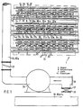
- FIG. 1 and 1a show two coke ovens 2, 3 of a coke oven battery 1, in which oven chambers 4 are delimited on both sides by heating walls 5.
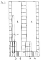
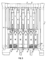
- the heating walls 5 contain a plurality of heating elements 6, 7, see also FIG. 2, which correspond to one another in that the gas combustion takes place in the heating elements 6 and the hot exhaust gases are removed in the heating element 7. From time to time, the heating system is changed so that the combustion the gases in the heating element 7a and the removal of the hot exhaust gases in the heating element 6a. This is due to the fact that the coke ovens 2, 3 are operated in regenerator mode (FIGS. 4 and 5).
- the regenerative chamber 40 is alternately supplied with the exhaust gas from the heating trains 7 and 6a, which heats up the regenerator trim 42, and the regenerator trim 42 heats the flowing lean gas or the flowing air after each changeover before these media enter the heating trains 6 or 6. 7a arrive.
- the coke ovens 2, 3 can be heated bivalent.
- this gas passes from weak gas channels 44 via regenerator 40 and weak gas channels 20 or 21a and, on the other hand, the air from air channels 45 likewise via regenerator 40 and air channels 22 or 23a into heating trains 6 or 7a.
- the exhaust gas from the heating trains 7 and 6a is returned to the regenerators 40 via exhaust gas channels 21, 23, 25 and 20a, 22a, 24a and discharged via exhaust gas channels 46, 47.
- the strong gas passes from a strong gas line 26 via gas supply lines 8, 9 and via gas branch lines 12, 13 into gas supply lines 16, 17 and 16a, 17a and is led from there into the heating cables 6, 7a.
- an air line 32 is provided, to which air supply lines 10, 11 or exhaust gas supply lines 10a, 11a connect, which in turn merge into air supply lines 18, 19 or exhaust gas supply lines 18a, 19a via air branch lines 14, 15 or exhaust gas branch lines 14a, 15a, from which the heating cables 6, 7a can be charged with additional air or with exhaust gas as a leaner.
- additional air can be introduced through the channels 20 or 21a during high-gas operation if the air from the channels 22, 24 or 23a, 25a is not sufficient to ensure sufficient combustion of the high-pressure gas.
- additional air or additional high-pressure gas can be introduced into the heating trains 6, 7a.
- additional air or exhaust gas can be indicated in the heating trains 6, 7a to optimize the combustion management or the NO x content of the flue gases.
- the high-pressure gas line 26 is once equipped with a control flap 28.
- it has a shut-off valve 29 which can be bypassed via a bypass line 27, which in turn has a control flap 30 for fine gas control in order to meter in small amounts of heavy gas during low-gas operation.
- the bypass line 27 can in turn be shut off by a shut-off valve 31 if the rough control via the control flap 28 is sufficient in the case of strong gas heating.
- the air line 32 also has a control flap 33. While the feeds to the air channels 22, 24 or 23a, 25a in the usual way (not shown here) through the chimney via air inlet flaps into the regenerators 40 and further into the Schuman 6, 7a is sucked and the height and The diameter of the chimney or the exhaust gas temperature and the temperature of the outside air are decisive for the air intake, the additional air or the exhaust gas is expediently entered with the aid of a fan 34.
- the switch from aviation to exhaust gas travel is achieved in that the air inlet is closed via a blind flange 36 and the chimney fox 35 is connected by opening a shut-off valve 38. To switch back to forced air travel, the chimney fox can be pushed off via a plug-in disk 37.
- attachment nozzle 39 in the air supply 18, 19 and exhaust gas supply 18a may be used 19a to the flame shape as to control or change that harmful substances NO x can be minimized in the exhaust gas, in particular.
- outlets or inlets to the regenerators 40 can be equipped with slides 43.
Landscapes
- Chemical & Material Sciences (AREA)
- Engineering & Computer Science (AREA)
- Combustion & Propulsion (AREA)
- Materials Engineering (AREA)
- Oil, Petroleum & Natural Gas (AREA)
- Organic Chemistry (AREA)
- Coke Industry (AREA)
- Waste-Gas Treatment And Other Accessory Devices For Furnaces (AREA)
Applications Claiming Priority (3)
| Application Number | Priority Date | Filing Date | Title |
|---|---|---|---|
| DE4214137 | 1992-04-29 | ||
| DE19924214137 DE4214137C1 (enExample) | 1992-04-29 | 1992-04-29 | |
| PCT/EP1993/001019 WO1993022398A1 (de) | 1992-04-29 | 1993-04-27 | Koksofen |
Publications (2)
| Publication Number | Publication Date |
|---|---|
| EP0638113A1 EP0638113A1 (de) | 1995-02-15 |
| EP0638113B1 true EP0638113B1 (de) | 1995-11-15 |
Family
ID=6457756
Family Applications (1)
| Application Number | Title | Priority Date | Filing Date |
|---|---|---|---|
| EP93909849A Expired - Lifetime EP0638113B1 (de) | 1992-04-29 | 1993-04-27 | Koksofen |
Country Status (3)
| Country | Link |
|---|---|
| EP (1) | EP0638113B1 (enExample) |
| DE (1) | DE4214137C1 (enExample) |
| WO (1) | WO1993022398A1 (enExample) |
Families Citing this family (1)
| Publication number | Priority date | Publication date | Assignee | Title |
|---|---|---|---|---|
| CN105670650B (zh) * | 2016-01-21 | 2019-07-23 | 金能科技股份有限公司 | 减少焦炉氮氧化物产生的装置及方法 |
Family Cites Families (4)
| Publication number | Priority date | Publication date | Assignee | Title |
|---|---|---|---|---|
| US3433715A (en) * | 1966-01-18 | 1969-03-18 | Koppers Co Inc | Heating high chambered horizontal coke ovens |
| US3494833A (en) * | 1966-01-24 | 1970-02-10 | Walter Grumm | Coke oven battery including high and low rich gas burners |
| DE2154412A1 (de) * | 1971-11-02 | 1973-05-03 | Otto & Co Gmbh Dr C | Batterieweise angeordnete, regenerativ beheizte verkokungsoefen |
| DE3900860A1 (de) * | 1989-01-13 | 1990-07-19 | Ruhrkohle Ag | Koksofen |
-
1992
- 1992-04-29 DE DE19924214137 patent/DE4214137C1/de not_active Expired - Fee Related
-
1993
- 1993-04-27 EP EP93909849A patent/EP0638113B1/de not_active Expired - Lifetime
- 1993-04-27 WO PCT/EP1993/001019 patent/WO1993022398A1/de not_active Ceased
Also Published As
| Publication number | Publication date |
|---|---|
| DE4214137C1 (enExample) | 1993-08-19 |
| WO1993022398A1 (de) | 1993-11-11 |
| EP0638113A1 (de) | 1995-02-15 |
Similar Documents
| Publication | Publication Date | Title |
|---|---|---|
| EP0373358B1 (de) | Verfahren zur Verringerung des NOx-Gehaltes im Abgas bei der Beheizung von Starkgas- oder Verbundkoksöfen und Koksofenbatterie zur Durchführung des Verfahrens | |
| EP1390679A1 (de) | Trockner | |
| DE3339972C2 (de) | Kammerringofen und Verfahren zu dessen Betrieb | |
| EP4327039A1 (de) | Werkstückbearbeitungsanlage und verfahren zum herstellen und betreiben einer solchen werkstückbearbeitungsanlage | |
| EP0617231A1 (de) | Verfahren zum Betrieb eines Ölverdampfungsbrenners und Ölverdampfungsbrenner | |
| EP0638113B1 (de) | Koksofen | |
| DE1868003U (de) | Brenner fuer kohlenstaubfeuerungen. | |
| EP2096356A2 (de) | Ofen | |
| EP0002702B1 (de) | Etagenbackofen mit Heizgasumwälzheizung | |
| DE2711883A1 (de) | Regenerativkoksofenbatterie | |
| AT503346B1 (de) | Verbrennungsvorrichtung mit einer einrichtung zur regelung der luftzufuhr | |
| DE60014213T2 (de) | Koksofen und Verfahren zum Betrieb desselben | |
| DE3628675C1 (de) | Druckaufgeladene Wirbelschichtfeuerung | |
| EP0474681B1 (de) | Beheizungssystem für regenerativverkokungsöfen | |
| AT405763B (de) | Heizungskessel mit einem oberen brennstoff-füllraum | |
| EP0226731B1 (de) | Vorrichtung zum Vermindern der Schadstoffemissionen in Rauchgasen von Feuerungsanlagen | |
| DE102022206343B3 (de) | Holzbefeuerter Backofen | |
| EP1771683B1 (de) | Thermische nachverbrennungsvorrichtung sowie verfahren zum betreiben einer solchen | |
| DE3210368C2 (enExample) | ||
| DE3205640A1 (de) | Brenner und verfahren fuer die verbrennung mehrerer brennstoffe | |
| DE3913316C2 (de) | Verfahren zum Beheizen einer Regenerativ-Koksofenbatterie sowie Regenerativ-Koksofenbatterie mit einer solchen Beheizung | |
| DE515855C (de) | Regenerativofen, insbesondere metallurgischer Schmelzofen | |
| DE904887C (de) | Rekuperativ-Koksofengruppe fuer die Beheizung mittels Stark- oder Schwachgas | |
| DE248523C (enExample) | ||
| DE441422C (de) | Regenerativkoksofenbatterie mit stehenden Retorten |
Legal Events
| Date | Code | Title | Description |
|---|---|---|---|
| PUAI | Public reference made under article 153(3) epc to a published international application that has entered the european phase |
Free format text: ORIGINAL CODE: 0009012 |
|
| 17P | Request for examination filed |
Effective date: 19940929 |
|
| AK | Designated contracting states |
Kind code of ref document: A1 Designated state(s): BE FR GB IT NL |
|
| 17Q | First examination report despatched |
Effective date: 19950503 |
|
| ITF | It: translation for a ep patent filed | ||
| GRAA | (expected) grant |
Free format text: ORIGINAL CODE: 0009210 |
|
| AK | Designated contracting states |
Kind code of ref document: B1 Designated state(s): BE FR GB IT NL |
|
| GBT | Gb: translation of ep patent filed (gb section 77(6)(a)/1977) |
Effective date: 19951220 |
|
| ET | Fr: translation filed | ||
| PLBE | No opposition filed within time limit |
Free format text: ORIGINAL CODE: 0009261 |
|
| STAA | Information on the status of an ep patent application or granted ep patent |
Free format text: STATUS: NO OPPOSITION FILED WITHIN TIME LIMIT |
|
| 26N | No opposition filed | ||
| REG | Reference to a national code |
Ref country code: GB Ref legal event code: IF02 |
|
| PGFP | Annual fee paid to national office [announced via postgrant information from national office to epo] |
Ref country code: FR Payment date: 20030310 Year of fee payment: 11 |
|
| PGFP | Annual fee paid to national office [announced via postgrant information from national office to epo] |
Ref country code: GB Payment date: 20030313 Year of fee payment: 11 |
|
| PGFP | Annual fee paid to national office [announced via postgrant information from national office to epo] |
Ref country code: NL Payment date: 20030325 Year of fee payment: 11 |
|
| PGFP | Annual fee paid to national office [announced via postgrant information from national office to epo] |
Ref country code: BE Payment date: 20030402 Year of fee payment: 11 |
|
| PG25 | Lapsed in a contracting state [announced via postgrant information from national office to epo] |
Ref country code: GB Free format text: LAPSE BECAUSE OF NON-PAYMENT OF DUE FEES Effective date: 20040427 |
|
| PG25 | Lapsed in a contracting state [announced via postgrant information from national office to epo] |
Ref country code: BE Free format text: LAPSE BECAUSE OF NON-PAYMENT OF DUE FEES Effective date: 20040430 |
|
| BERE | Be: lapsed |
Owner name: *RUHRKOHLE A.G. Effective date: 20040430 |
|
| PG25 | Lapsed in a contracting state [announced via postgrant information from national office to epo] |
Ref country code: NL Free format text: LAPSE BECAUSE OF NON-PAYMENT OF DUE FEES Effective date: 20041101 |
|
| GBPC | Gb: european patent ceased through non-payment of renewal fee |
Effective date: 20040427 |
|
| PG25 | Lapsed in a contracting state [announced via postgrant information from national office to epo] |
Ref country code: FR Free format text: LAPSE BECAUSE OF NON-PAYMENT OF DUE FEES Effective date: 20041231 |
|
| NLV4 | Nl: lapsed or anulled due to non-payment of the annual fee |
Effective date: 20041101 |
|
| REG | Reference to a national code |
Ref country code: FR Ref legal event code: ST |
|
| PG25 | Lapsed in a contracting state [announced via postgrant information from national office to epo] |
Ref country code: IT Free format text: LAPSE BECAUSE OF NON-PAYMENT OF DUE FEES;WARNING: LAPSES OF ITALIAN PATENTS WITH EFFECTIVE DATE BEFORE 2007 MAY HAVE OCCURRED AT ANY TIME BEFORE 2007. THE CORRECT EFFECTIVE DATE MAY BE DIFFERENT FROM THE ONE RECORDED. Effective date: 20050427 |