EP0638113B1 - Koksofen - Google Patents
Koksofen Download PDFInfo
- Publication number
- EP0638113B1 EP0638113B1 EP93909849A EP93909849A EP0638113B1 EP 0638113 B1 EP0638113 B1 EP 0638113B1 EP 93909849 A EP93909849 A EP 93909849A EP 93909849 A EP93909849 A EP 93909849A EP 0638113 B1 EP0638113 B1 EP 0638113B1
- Authority
- EP
- European Patent Office
- Prior art keywords
- gas
- air
- heating
- duct
- coke oven
- Prior art date
- Legal status (The legal status is an assumption and is not a legal conclusion. Google has not performed a legal analysis and makes no representation as to the accuracy of the status listed.)
- Expired - Lifetime
Links
Images


Classifications
-
- C—CHEMISTRY; METALLURGY
- C10—PETROLEUM, GAS OR COKE INDUSTRIES; TECHNICAL GASES CONTAINING CARBON MONOXIDE; FUELS; LUBRICANTS; PEAT
- C10B—DESTRUCTIVE DISTILLATION OF CARBONACEOUS MATERIALS FOR PRODUCTION OF GAS, COKE, TAR, OR SIMILAR MATERIALS
- C10B5/00—Coke ovens with horizontal chambers
- C10B5/02—Coke ovens with horizontal chambers with vertical heating flues
-
- C—CHEMISTRY; METALLURGY
- C10—PETROLEUM, GAS OR COKE INDUSTRIES; TECHNICAL GASES CONTAINING CARBON MONOXIDE; FUELS; LUBRICANTS; PEAT
- C10B—DESTRUCTIVE DISTILLATION OF CARBONACEOUS MATERIALS FOR PRODUCTION OF GAS, COKE, TAR, OR SIMILAR MATERIALS
- C10B21/00—Heating of coke ovens with combustible gases
- C10B21/10—Regulating and controlling the combustion
-
- C—CHEMISTRY; METALLURGY
- C10—PETROLEUM, GAS OR COKE INDUSTRIES; TECHNICAL GASES CONTAINING CARBON MONOXIDE; FUELS; LUBRICANTS; PEAT
- C10B—DESTRUCTIVE DISTILLATION OF CARBONACEOUS MATERIALS FOR PRODUCTION OF GAS, COKE, TAR, OR SIMILAR MATERIALS
- C10B21/00—Heating of coke ovens with combustible gases
- C10B21/20—Methods of heating ovens of the chamber oven type
- C10B21/22—Methods of heating ovens of the chamber oven type by introducing the heating gas and air at various levels
Definitions
- the invention relates to a coke oven with heating trains, wherein each heating train is equipped with an exhaust gas recirculation and is provided with at least two gas feeds and two air feeds and one of the two gas feeds can alternatively serve as an additional air feed.
- gas is diluted in high-pressure gas supply lines by metering in recirculated exhaust gas in order to prevent the risk of carbon deposits in the lines. It is disadvantageous that each heating train is assigned its own mixing device and that each must obtain exhaust gas from the neighboring heating train via the adjacent strong gas supply line.
- DE-OS 39 00 860 discloses a type-like assembly of the heating trains of a bivalent coke oven with at least two gas feeds and two air feeds. Since ceramic parts in the area of the gas supply or air supply can be damaged, spalling occasionally occurs, which obstructs the gas path / air path. This inevitably leads to a malfunction in the heating system - in other words, to an unevenness that is avoided by the additional or alternative gas or air supplies.
- a special feature of this coke oven is also that a Flap control is provided for heavy gas operation and a bypass line with a smaller cross-section with flap is assigned to the flap control for fine regulation of additional high gas via the second gas supply in the case of low gas operation.
- the aim is to keep the NO x generated during the combustion process as far as possible below certain predetermined limit values.
- the object of the present invention is to reduce the amount of NO x in addition to improved combustion management in coke ovens of the type mentioned. According to the invention this is achieved in coke ovens with at least one second gas supply or air supply or for each heating train by the characterizing features of claim 1. A further training is set out in sub-claim 2.
- the advantages of the coke ovens according to the invention are, in particular, the diverse regulation options for optimization the heating and to minimize the pollutants, in particular the NO x , in the flue gas in bivalent coke ovens which can alternatively be operated in lean gas and / or high gas operation.
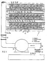
- FIG. 1 and 1a show two coke ovens 2, 3 of a coke oven battery 1, in which oven chambers 4 are delimited on both sides by heating walls 5.
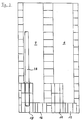
- the heating walls 5 contain a plurality of heating elements 6, 7, see also FIG. 2, which correspond to one another in that the gas combustion takes place in the heating elements 6 and the hot exhaust gases are removed in the heating element 7. From time to time, the heating system is changed so that the combustion the gases in the heating element 7a and the removal of the hot exhaust gases in the heating element 6a. This is due to the fact that the coke ovens 2, 3 are operated in regenerator mode (FIGS. 4 and 5).
- the regenerative chamber 40 is alternately supplied with the exhaust gas from the heating trains 7 and 6a, which heats up the regenerator trim 42, and the regenerator trim 42 heats the flowing lean gas or the flowing air after each changeover before these media enter the heating trains 6 or 6. 7a arrive.
- the coke ovens 2, 3 can be heated bivalent.
- this gas passes from weak gas channels 44 via regenerator 40 and weak gas channels 20 or 21a and, on the other hand, the air from air channels 45 likewise via regenerator 40 and air channels 22 or 23a into heating trains 6 or 7a.
- the exhaust gas from the heating trains 7 and 6a is returned to the regenerators 40 via exhaust gas channels 21, 23, 25 and 20a, 22a, 24a and discharged via exhaust gas channels 46, 47.
- the strong gas passes from a strong gas line 26 via gas supply lines 8, 9 and via gas branch lines 12, 13 into gas supply lines 16, 17 and 16a, 17a and is led from there into the heating cables 6, 7a.
- an air line 32 is provided, to which air supply lines 10, 11 or exhaust gas supply lines 10a, 11a connect, which in turn merge into air supply lines 18, 19 or exhaust gas supply lines 18a, 19a via air branch lines 14, 15 or exhaust gas branch lines 14a, 15a, from which the heating cables 6, 7a can be charged with additional air or with exhaust gas as a leaner.
- additional air can be introduced through the channels 20 or 21a during high-gas operation if the air from the channels 22, 24 or 23a, 25a is not sufficient to ensure sufficient combustion of the high-pressure gas.
- additional air or additional high-pressure gas can be introduced into the heating trains 6, 7a.
- additional air or exhaust gas can be indicated in the heating trains 6, 7a to optimize the combustion management or the NO x content of the flue gases.
- the high-pressure gas line 26 is once equipped with a control flap 28.
- it has a shut-off valve 29 which can be bypassed via a bypass line 27, which in turn has a control flap 30 for fine gas control in order to meter in small amounts of heavy gas during low-gas operation.
- the bypass line 27 can in turn be shut off by a shut-off valve 31 if the rough control via the control flap 28 is sufficient in the case of strong gas heating.
- the air line 32 also has a control flap 33. While the feeds to the air channels 22, 24 or 23a, 25a in the usual way (not shown here) through the chimney via air inlet flaps into the regenerators 40 and further into the Schuman 6, 7a is sucked and the height and The diameter of the chimney or the exhaust gas temperature and the temperature of the outside air are decisive for the air intake, the additional air or the exhaust gas is expediently entered with the aid of a fan 34.
- the switch from aviation to exhaust gas travel is achieved in that the air inlet is closed via a blind flange 36 and the chimney fox 35 is connected by opening a shut-off valve 38. To switch back to forced air travel, the chimney fox can be pushed off via a plug-in disk 37.
- attachment nozzle 39 in the air supply 18, 19 and exhaust gas supply 18a may be used 19a to the flame shape as to control or change that harmful substances NO x can be minimized in the exhaust gas, in particular.
- outlets or inlets to the regenerators 40 can be equipped with slides 43.
Landscapes
- Chemical & Material Sciences (AREA)
- Engineering & Computer Science (AREA)
- Materials Engineering (AREA)
- Oil, Petroleum & Natural Gas (AREA)
- Organic Chemistry (AREA)
- Combustion & Propulsion (AREA)
- Coke Industry (AREA)
- Waste-Gas Treatment And Other Accessory Devices For Furnaces (AREA)
Abstract
Description
- Die Erfindung betrifft einen Koksofen mit Heizzügen, wobei jeder Heizzug mit einer Abgasrückführung ausgerüstet ist und mit mindestens zwei Gaszuführungen sowie zwei Luftzuführungen versehen ist und eine der beiden Gaszuführungen alternativ als zusätzliche Luftzuführung dienen kann. Bei diesem aus der DE-A-1 671 318 bekannten, bivalent betreibbaren Koksofen wird in Starkgas-Zuführungsleitungen eine Gasverdünnung durch Eindosieren von rückgeführtem Abgas vorgenommen, um der Gefahr von Kohlenstoffablagerungen in den Leitungen vorzubeugen. Dabei ist es nachteilig, daß jedem Heizzug eine eigene Mischvorrichtung zugeordnet ist und diese jeweils vom benachbarten Heizzug Abgas über die benachbarte Starkgas-Zuführungsleitung beziehen muß.
- Aus der DE-OS 39 00 860 ist eine gattungsähnliche Bestückung der Heizzüge eines bivalent betreibbaren Koksofens mit mindestens zwei Gaszuführungen und zwei Luftzuführungen bekannt. Da keramische Teile im Bereich der Gaszuführung bzw. Luftzuführung beschädigt werden können, treten gelegentlich Abplatzungen auf, die den Gasweg/Luftweg verlegen. Das führt zwangsläufig zu einer Störung der Beheizung - also zu einer Ungleichmäßigkeit, die durch die ergänzenden bzw. alternativen Gas- bzw. Luftzuführungen vermieden wird. Eine Besonderheit dieses Koksofens ist außerdem, daß in einer Starkgasleitung eine Klappenregelung für den Starkgasbetrieb vorgesehen ist und der Klappenregelung zur Feinregulierung von Zusatzstarkgas über die zweite Gaszuführung bei Schwachgasbetrieb eine Bypaßleitung kleineren Querschnitts mit Klappe zugeordnet ist.
- Es wird aus Gründen des Umweltschutzes angestrebt, das beim Verbrennungsvorgang entstehende NOx möglichst unterhalb bestimmter vorgegebener Grenzwerte zu halten.
- Aufgabe der vorliegenden Erfindung ist es, bei Koksöfen der eingangs genannten Gattung neben einer verbesserten Verbrennungsführung den NOx-Anteil zu verringern. Nach der Erfindung wird das bei Koksöfen mit mindestens einer zweiten Gaszuführung bzw. Luftzuführung bzw. für jeden Heizzug durch die kennzeichnenden Merkmale des Patentanspruchs 1 erreicht. Eine Weiterbildung ist in Unteranspruch 2 niedergelegt.
- Die Vorteile der erfindungsgemäßen Koksöfen sind insbesondere die vielfältigen Regulierungsmöglichkeiten zur Optimierung der Beheizung und zur Minimierung der Schadstoffe, insbesondere des NOx, im Rauchgas bei bivalenten Koksöfen, die alternativ im Schwachgas- und/oder Starkgasbetrieb betreibbar sind.
- Die Erfindung wird nachfolgend anhand der Zeichnung näher erläutert. Die Zeichnung besteht aus folgenden Figuren.
- Figur 1 und 1a
- zeigen in einer zweiteiligen schematischen Darstellung einen Querschnitt durch eine Koksofenbatterie in Verbindung mit der Leitungsführung für Luft, Gas und Abgas, wobei Fig. 1 die linke Seite und Fig. 1a die rechte Seite der Koksofenbatterie wiedergeben,
- Figur 2
- einen Schnitt durch eine Heizwand,
- Figur 3
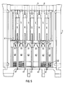
- als Einzelheit aus Figur 2 die Darstellung von zwei Heizzügen,
- Figur 4
- einen Teilquerschnitt durch den Regeneratorbereich und
- Figur 5
- einen Teilquerschnitt durch eine Koksofenbatterie.
- In Figur 1 und 1a sind zwei Koksöfen 2, 3 einer Koksofenbatterie 1 dargestellt, bei denen Ofenkammern 4 beiderseits von Heizwänden 5 begrenzt werden. Die Heizwände 5 enthalten eine Vielzahl von Heizzügen 6, 7, - siehe auch Fig. 2 - die jeweils miteinander korrespondieren, indem in den Heizzügen 6 die Gasverbrennung erfolgt und im Heizzug 7 die heißen Abgase abgeführt werden. Von Zeit zu Zeit erfolgt eine Umstellung der Heizungsführung dergestalt, daß die Verbrennung der Gase im Heizzug 7a und die Abführung der heißen Abgasen im Heizzug 6a vonstatten gehen. Dies beruht darauf, daß die Koksöfen 2, 3 im Regeneratorbetrieb betrieben werden (Figur 4 und 5). Dabei wird einer Regeneratorkammer 40 wechselweise das Abgas aus den Heizzügen 7 bzw. 6a zugeführt, das den Regeneratorbesatz 42 aufheizt, und der Regeneratorbesatz 42 jeweils nach erfolgter Umstellung das durchströmende Schwachgas bzw. die durchströmende Luft erwärmt, bevor diese Medien in die Heizzüge 6 bzw. 7a gelangen.
- Die Koksöfen 2, 3 sind bivalent beheizbar. Bei Schwachgasbeheizung (Figur 4) gelangt dieses Gas aus Schwachgaskanälen 44 über den Regenerator 40 und Schwachgaskanäle 20 bzw. 21a sowie andererseits die Luft aus Luftkanälen 45 ebenfalls über Regenerator 40 und Luftkanäle 22 bzw. 23a in die Heizzüge 6 bzw. 7a.
- In Gegenrichtung wird das Abgas aus den Heizzügen 7 bzw. 6a über Abgaskanäle 21, 23, 25 bzw. 20a, 22a, 24a in die Regeneratoren 40 zurückgeleitet und über Abgaskanäle 46, 47 abgeführt.
- Bei Starkgasbeheizung (Fig. 1a) gelangt das Starkgas aus einer Starkgasleitung 26 über Gaszuführungsleitungen 8, 9 sowie über Gasabzweigleitungen 12, 13 in Gaszuführungen 16, 17 bzw. 16a, 17a und wird von dort in die Heizzüge 6, 7a geführt. Weiterhin ist gemäß Figur 1 eine Luftleitung 32 vorgesehen, an die Luftzuführungsleitungen 10, 11 bzw. Abgaszuführungsleitungen 10a, 11a anschließen, die ihrerseits über Luftabzweigleitungen 14, 15 bzw. Abgasabzweigleitungen 14a, 15a in Luftzuführungen 18, 19 bzw. Abgaszuführungen 18a, 19a übergehen, aus denen die Heizzüge 6, 7a mit Zusatzluft bzw. mit Abgas als Abmagerungsmittel beschickt werden können.
- Anstelle von Schwachgas kann durch die Kanäle 20 bzw. 21a bei Starkgasbetrieb Zusatzluft eingetragen werden, wenn die Luft aus den Kanälen 22, 24 bzw. 23a, 25a nicht ausreicht, um eine ausreichende Verbrennung des Starkgases zu gewährleisten.
- Darüber hinaus besteht über die Luftzuführungsleitungen 10, 11 bzw. Abgaszuführungsleitungen 10a, 11a eine beliebige Kombinationsmöglichkeit, das jeweilige Gas-Luft-Gemisch in den Heizzügen 6 bzw. 7a hinsichtlich des Heizwertes dieses Brennstoff-Gemisches zu optimieren oder hinsichtlich des NOx-Gehaltes der Rauchgase zu minimieren.
- Beispielsweise kann bei Schwachgasbetrieb Zusatzluft oder zusätzlich Starkgas in die Heizzüge 6, 7a eingetragen werden. Bei Starkgasbeheizung kann entweder Zusatzluft oder Abgas in die Heizzüge 6, 7a zur Optimierung der Verbrennungsführung oder des NOx-Gehaltes der Rauchgase indiziert werden. Zu diesem Zweck ist die Starkgasleitung 26 einmal mit einer Regelklappe 28 ausgestattet. Andererseits verfügt sie über eine Absperrarmatur 29, die über eine Bypaßleitung 27 umgehbar ist, die ihrerseits über eine Regelklappe 30 zur Feingasregelung verfügt, um bei Schwachgasbetrieb geringe Starkgasmengen zuzudosieren. Die Bypaßleitung 27 ist ihrerseits über eine Absperrarmatur 31 absperrbar, wenn die Grobregelung über die Regelklappe 28 bei Starkgasbeheizung ausreichend ist.
- Die Luftleitung 32, alternativ Abgasleitung 32a, verfügt ebenfalls über eine Regelklappe 33. Während die Zuführungen zu den Lufkanälen 22, 24 bzw. 23a, 25a in üblicher Weise (hier nicht dargestellt) durch den Schornstein über Lufteinfallklappen in die Regeneratoren 40 und weiter in die Heizzüge 6, 7a gesaugt wird und hierbei die Höhe und der Durchmesser des Schornsteins oder auch die Abgastemperatur und die Temperatur der Außenluft für den Lufteinfall maßgebend sind, wird die Zusatzluft bzw. das Abgas zweckmäßig mit Hilfe eines Gebläses 34 eingetragen. Konstruktiv wird das Umschalten von Luftfahrt zu Abgasfahrt dadurch gelöst, daß der Lufteintrag über einen Blindflansch 36 verschlossen wird und der Kaminfuchs 35 durch Öffnen einer Absperrarmatur 38 angeschlossen wird. Zum erneuten Umschalten auf Zwangsluftfahrt kann der Kaminfuchs über eine Steckscheibe 37 abgeschiebert werden.
- Wie aus Figur 3 hervorgeht können Aufsatzdüsen 39 in die Luftzuführung 18, 19 bzw. Abgaszuführung 18a, 19a eingesetzt werden, um die Flammenform so zu steuern bzw. zu ändern, daß schädliche Stoffe, insbesondere NOx, im Abgas minimiert werden können.
- Gemäß Figur 4 können die Auslässe bzw. Einlässe zu den Regeneratoren 40 mit Schiebern 43 ausgerüstet sein.
-
- 1
- Koksofenbatterie
- 2
- Koksofen
- 3
- Koksofen
- 4
- Koksofenkammer
- 5
- Heizwand
- 6
- Heizzug
- 6a
- Heizzug (umgestellt)
- 7
- Heizzug
- 7a
- Heizzug (umgestellt)
- 8
- Gaszuführungsleitung
- 9
- Gaszuführungsleitung
- 10
- Luftzuführungsleitung
- 10a
- Abgaszuführungsleitung
- 11
- Luftzuführungsleitung
- 11a
- Abgaszuführungsleitung
- 12
- Gasabzweigleitung
- 13
- Gasabzweigleitung
- 14
- Luftabzweigleitung
- 14a
- Abgasabzweigleitung
- 15
- Luftabzweigleitung
- 15a
- Abgasabzweigleitung
- 16
- Gaszuführung
- 16a
- Gaszuführung (umgestellt)
- 17
- Gaszuführung
- 17a
- Gaszuführung (umgestellt)
- 18
- Luftzuführung
- 18a
- Luftzuführung (umgestellt)
- 19
- Luftzuführung
- 19a
- Luftzuführung (umgestellt)
- 20
- Schwachgaskanal
- 20a
- Abgaskanal (umgestellt)
- 21
- Abgaskanal
- 21a
- Schwachgaskanal (umgestellt)
- 22
- Luftkanal
- 22a
- Abgaskanal (umgestellt)
- 23
- Abgaskanal
- 23a
- Luftkanal (umgestellt)
- 24
- Luftkanal
- 24a
- Abgaskanal (umgestellt)
- 25
- Abgaskanal
- 25a
- Luftkanal (umgestellt)
- 26
- Starkgasleitung
- 27
- Bypaßleitung
- 28
- Regelklappe
- 29
- Absperrarmatur
- 30
- Regelklappe
- 31
- Absperrarmatur
- 32
- Luftleitung
- 32a
- Abgasleitung
- 33
- Regelklappe
- 34
- Gebläse
- 35
- Abgaskaminfuchs
- 36
- Blindflansch (Abgasfahrt)
- 37
- Steckscheibe (Zwangsluftfahrt)
- 38
- Absperrarmatur
- 39
- Aufsatzdüse
- 40
- Regenerator
- 41
- Ofensohle
- 42
- Regeneratorbesatz
- 43
- Schieber
- 44
- Schwachgaskanal
- 45
- Luftkanal
- 46
- Abgaskanal
- 47
- Abgaskanal
Claims (2)
- Koksofen mit Heizzügen in der Heizwand, wobei jeder Heizzug (6 bzw. 7a) mit einer Abgasrückführung (32a) ausgerüstet ist, mindestens mit zwei Gaszuführungen (20, 17 bzw. 21a, 16) sowie zwei Luftzuführungen (22, 24 bzw. 23a, 24a) versehen ist und eine der beiden Gaszuführungen (20 bzw. 21a) alternativ als zusätzliche Luftzuführung dienen kann, dadurch gekennzeichnet , daß eine weitere zusätzliche Luftzuführung (19 bzw. 18) an eine Luftleitung (32) anschließbar ist, die zwecks Zwangsluftzuführung über ein Gebläse (34) verfügt und die alternativ als Abgaszuführung (18a bzw. 19a) mit einer Abgasleitung (32a) verbindbar ist, die an den Abgaskaminfuchs (35) anschließbar ist und daß in einer Starkgasleitung (26) eine Klappenregelung (28) für den Starkgasbetrieb vorgesehen ist und der Klappenregelung (28) zur Feinregelung von Zusatzstarkgas über die zweite Gaszuführung (16, 17) bei Schwachgasbetrieb eine Bypaßleitung (27) kleineren Querschnitts mit Klappe (30) zugeordnet ist.
- Koksofen nach Anspruch 1, dadurch gekennzeichnet, daß die zweite Gaszuführung (16, 17) mit einer Aufsatzdüse (39) zur Steuerung bzw. Änderung der Flammenform versehen ist.
Applications Claiming Priority (3)
| Application Number | Priority Date | Filing Date | Title |
|---|---|---|---|
| DE19924214137 DE4214137C1 (de) | 1992-04-29 | 1992-04-29 | |
| DE4214137 | 1992-04-29 | ||
| PCT/EP1993/001019 WO1993022398A1 (de) | 1992-04-29 | 1993-04-27 | Koksofen |
Publications (2)
| Publication Number | Publication Date |
|---|---|
| EP0638113A1 EP0638113A1 (de) | 1995-02-15 |
| EP0638113B1 true EP0638113B1 (de) | 1995-11-15 |
Family
ID=6457756
Family Applications (1)
| Application Number | Title | Priority Date | Filing Date |
|---|---|---|---|
| EP93909849A Expired - Lifetime EP0638113B1 (de) | 1992-04-29 | 1993-04-27 | Koksofen |
Country Status (3)
| Country | Link |
|---|---|
| EP (1) | EP0638113B1 (de) |
| DE (1) | DE4214137C1 (de) |
| WO (1) | WO1993022398A1 (de) |
Families Citing this family (1)
| Publication number | Priority date | Publication date | Assignee | Title |
|---|---|---|---|---|
| CN105670650B (zh) * | 2016-01-21 | 2019-07-23 | 金能科技股份有限公司 | 减少焦炉氮氧化物产生的装置及方法 |
Family Cites Families (4)
| Publication number | Priority date | Publication date | Assignee | Title |
|---|---|---|---|---|
| US3433715A (en) * | 1966-01-18 | 1969-03-18 | Koppers Co Inc | Heating high chambered horizontal coke ovens |
| US3494833A (en) * | 1966-01-24 | 1970-02-10 | Walter Grumm | Coke oven battery including high and low rich gas burners |
| DE2154412A1 (de) * | 1971-11-02 | 1973-05-03 | Otto & Co Gmbh Dr C | Batterieweise angeordnete, regenerativ beheizte verkokungsoefen |
| DE3900860A1 (de) * | 1989-01-13 | 1990-07-19 | Ruhrkohle Ag | Koksofen |
-
1992
- 1992-04-29 DE DE19924214137 patent/DE4214137C1/de not_active Expired - Fee Related
-
1993
- 1993-04-27 WO PCT/EP1993/001019 patent/WO1993022398A1/de active IP Right Grant
- 1993-04-27 EP EP93909849A patent/EP0638113B1/de not_active Expired - Lifetime
Also Published As
| Publication number | Publication date |
|---|---|
| DE4214137C1 (de) | 1993-08-19 |
| WO1993022398A1 (de) | 1993-11-11 |
| EP0638113A1 (de) | 1995-02-15 |
Similar Documents
| Publication | Publication Date | Title |
|---|---|---|
| EP0373358B1 (de) | Verfahren zur Verringerung des NOx-Gehaltes im Abgas bei der Beheizung von Starkgas- oder Verbundkoksöfen und Koksofenbatterie zur Durchführung des Verfahrens | |
| EP1390679A1 (de) | Trockner | |
| EP0617231A1 (de) | Verfahren zum Betrieb eines Ölverdampfungsbrenners und Ölverdampfungsbrenner | |
| EP0638113B1 (de) | Koksofen | |
| DE1868003U (de) | Brenner fuer kohlenstaubfeuerungen. | |
| EP1771683B1 (de) | Thermische nachverbrennungsvorrichtung sowie verfahren zum betreiben einer solchen | |
| DE102012216756A1 (de) | Abgasrückführungs-Kühlungsmodul, Abgasrückführungsanlage sowie Verfahren zum Betrieb einer Abgasrückführungsanlage | |
| DE2711883A1 (de) | Regenerativkoksofenbatterie | |
| AT503346B1 (de) | Verbrennungsvorrichtung mit einer einrichtung zur regelung der luftzufuhr | |
| EP0002702B1 (de) | Etagenbackofen mit Heizgasumwälzheizung | |
| DE3628675C1 (de) | Druckaufgeladene Wirbelschichtfeuerung | |
| DE60014213T2 (de) | Koksofen und Verfahren zum Betrieb desselben | |
| EP0226731B1 (de) | Vorrichtung zum Vermindern der Schadstoffemissionen in Rauchgasen von Feuerungsanlagen | |
| EP0474681B1 (de) | Beheizungssystem für regenerativverkokungsöfen | |
| DE102022206343B3 (de) | Holzbefeuerter Backofen | |
| AT405763B (de) | Heizungskessel mit einem oberen brennstoff-füllraum | |
| DE3210368C2 (de) | ||
| DE3205640A1 (de) | Brenner und verfahren fuer die verbrennung mehrerer brennstoffe | |
| DE554156C (de) | Regenerativkoksofen | |
| DE3913316C2 (de) | Verfahren zum Beheizen einer Regenerativ-Koksofenbatterie sowie Regenerativ-Koksofenbatterie mit einer solchen Beheizung | |
| DE515855C (de) | Regenerativofen, insbesondere metallurgischer Schmelzofen | |
| DE904887C (de) | Rekuperativ-Koksofengruppe fuer die Beheizung mittels Stark- oder Schwachgas | |
| DE102021109810A1 (de) | Werkstückbearbeitungsanlage und verfahren zum herstellen und betreiben einer solchen werkstückbearbeitungsanlage | |
| DE248523C (de) | ||
| DE3231865C2 (de) |
Legal Events
| Date | Code | Title | Description |
|---|---|---|---|
| PUAI | Public reference made under article 153(3) epc to a published international application that has entered the european phase |
Free format text: ORIGINAL CODE: 0009012 |
|
| 17P | Request for examination filed |
Effective date: 19940929 |
|
| AK | Designated contracting states |
Kind code of ref document: A1 Designated state(s): BE FR GB IT NL |
|
| 17Q | First examination report despatched |
Effective date: 19950503 |
|
| ITF | It: translation for a ep patent filed |
Owner name: FIAMMENGHI - DOMENIGHETTI |
|
| GRAA | (expected) grant |
Free format text: ORIGINAL CODE: 0009210 |
|
| AK | Designated contracting states |
Kind code of ref document: B1 Designated state(s): BE FR GB IT NL |
|
| GBT | Gb: translation of ep patent filed (gb section 77(6)(a)/1977) |
Effective date: 19951220 |
|
| ET | Fr: translation filed | ||
| PLBE | No opposition filed within time limit |
Free format text: ORIGINAL CODE: 0009261 |
|
| STAA | Information on the status of an ep patent application or granted ep patent |
Free format text: STATUS: NO OPPOSITION FILED WITHIN TIME LIMIT |
|
| 26N | No opposition filed | ||
| REG | Reference to a national code |
Ref country code: GB Ref legal event code: IF02 |
|
| PGFP | Annual fee paid to national office [announced via postgrant information from national office to epo] |
Ref country code: FR Payment date: 20030310 Year of fee payment: 11 |
|
| PGFP | Annual fee paid to national office [announced via postgrant information from national office to epo] |
Ref country code: GB Payment date: 20030313 Year of fee payment: 11 |
|
| PGFP | Annual fee paid to national office [announced via postgrant information from national office to epo] |
Ref country code: NL Payment date: 20030325 Year of fee payment: 11 |
|
| PGFP | Annual fee paid to national office [announced via postgrant information from national office to epo] |
Ref country code: BE Payment date: 20030402 Year of fee payment: 11 |
|
| PG25 | Lapsed in a contracting state [announced via postgrant information from national office to epo] |
Ref country code: GB Free format text: LAPSE BECAUSE OF NON-PAYMENT OF DUE FEES Effective date: 20040427 |
|
| PG25 | Lapsed in a contracting state [announced via postgrant information from national office to epo] |
Ref country code: BE Free format text: LAPSE BECAUSE OF NON-PAYMENT OF DUE FEES Effective date: 20040430 |
|
| BERE | Be: lapsed |
Owner name: *RUHRKOHLE A.G. Effective date: 20040430 |
|
| PG25 | Lapsed in a contracting state [announced via postgrant information from national office to epo] |
Ref country code: NL Free format text: LAPSE BECAUSE OF NON-PAYMENT OF DUE FEES Effective date: 20041101 |
|
| GBPC | Gb: european patent ceased through non-payment of renewal fee |
Effective date: 20040427 |
|
| PG25 | Lapsed in a contracting state [announced via postgrant information from national office to epo] |
Ref country code: FR Free format text: LAPSE BECAUSE OF NON-PAYMENT OF DUE FEES Effective date: 20041231 |
|
| NLV4 | Nl: lapsed or anulled due to non-payment of the annual fee |
Effective date: 20041101 |
|
| REG | Reference to a national code |
Ref country code: FR Ref legal event code: ST |
|
| PG25 | Lapsed in a contracting state [announced via postgrant information from national office to epo] |
Ref country code: IT Free format text: LAPSE BECAUSE OF NON-PAYMENT OF DUE FEES;WARNING: LAPSES OF ITALIAN PATENTS WITH EFFECTIVE DATE BEFORE 2007 MAY HAVE OCCURRED AT ANY TIME BEFORE 2007. THE CORRECT EFFECTIVE DATE MAY BE DIFFERENT FROM THE ONE RECORDED. Effective date: 20050427 |