EP0637726A1 - Dispositif de refroidissement des gaz et éventuellement pour sécher de particules solides contenus dans le gaz - Google Patents
Dispositif de refroidissement des gaz et éventuellement pour sécher de particules solides contenus dans le gaz Download PDFInfo
- Publication number
- EP0637726A1 EP0637726A1 EP94111533A EP94111533A EP0637726A1 EP 0637726 A1 EP0637726 A1 EP 0637726A1 EP 94111533 A EP94111533 A EP 94111533A EP 94111533 A EP94111533 A EP 94111533A EP 0637726 A1 EP0637726 A1 EP 0637726A1
- Authority
- EP
- European Patent Office
- Prior art keywords
- gas
- reactor housing
- vortex
- solid particles
- liquid
- Prior art date
- Legal status (The legal status is an assumption and is not a legal conclusion. Google has not performed a legal analysis and makes no representation as to the accuracy of the status listed.)
- Granted
Links
- 239000007787 solid Substances 0.000 title claims abstract description 20
- 239000007789 gas Substances 0.000 title claims description 38
- 238000001035 drying Methods 0.000 title claims description 7
- 239000000112 cooling gas Substances 0.000 title claims description 5
- 239000007788 liquid Substances 0.000 claims abstract description 24
- 239000002245 particle Substances 0.000 claims abstract description 19
- 239000007921 spray Substances 0.000 claims abstract description 7
- 238000009434 installation Methods 0.000 claims description 26
- 238000001704 evaporation Methods 0.000 abstract description 4
- 230000008020 evaporation Effects 0.000 abstract description 4
- 230000035939 shock Effects 0.000 description 6
- 238000010276 construction Methods 0.000 description 5
- 230000001154 acute effect Effects 0.000 description 3
- 230000015572 biosynthetic process Effects 0.000 description 3
- 230000000694 effects Effects 0.000 description 3
- 238000004140 cleaning Methods 0.000 description 2
- 238000001816 cooling Methods 0.000 description 2
- 230000003068 static effect Effects 0.000 description 2
- 230000007704 transition Effects 0.000 description 2
- 238000006243 chemical reaction Methods 0.000 description 1
- 238000012423 maintenance Methods 0.000 description 1
- 230000000737 periodic effect Effects 0.000 description 1
- 230000006641 stabilisation Effects 0.000 description 1
- 238000011105 stabilization Methods 0.000 description 1
Images

Classifications
-
- F—MECHANICAL ENGINEERING; LIGHTING; HEATING; WEAPONS; BLASTING
- F26—DRYING
- F26B—DRYING SOLID MATERIALS OR OBJECTS BY REMOVING LIQUID THEREFROM
- F26B3/00—Drying solid materials or objects by processes involving the application of heat
- F26B3/02—Drying solid materials or objects by processes involving the application of heat by convection, i.e. heat being conveyed from a heat source to the materials or objects to be dried by a gas or vapour, e.g. air
- F26B3/10—Drying solid materials or objects by processes involving the application of heat by convection, i.e. heat being conveyed from a heat source to the materials or objects to be dried by a gas or vapour, e.g. air the gas or vapour carrying the materials or objects to be dried with it
- F26B3/12—Drying solid materials or objects by processes involving the application of heat by convection, i.e. heat being conveyed from a heat source to the materials or objects to be dried by a gas or vapour, e.g. air the gas or vapour carrying the materials or objects to be dried with it in the form of a spray, i.e. sprayed or dispersed emulsions or suspensions
-
- B—PERFORMING OPERATIONS; TRANSPORTING
- B01—PHYSICAL OR CHEMICAL PROCESSES OR APPARATUS IN GENERAL
- B01D—SEPARATION
- B01D1/00—Evaporating
- B01D1/16—Evaporating by spraying
- B01D1/18—Evaporating by spraying to obtain dry solids
-
- B—PERFORMING OPERATIONS; TRANSPORTING
- B01—PHYSICAL OR CHEMICAL PROCESSES OR APPARATUS IN GENERAL
- B01F—MIXING, e.g. DISSOLVING, EMULSIFYING OR DISPERSING
- B01F25/00—Flow mixers; Mixers for falling materials, e.g. solid particles
- B01F25/30—Injector mixers
- B01F25/31—Injector mixers in conduits or tubes through which the main component flows
- B01F25/313—Injector mixers in conduits or tubes through which the main component flows wherein additional components are introduced in the centre of the conduit
- B01F25/3131—Injector mixers in conduits or tubes through which the main component flows wherein additional components are introduced in the centre of the conduit with additional mixing means other than injector mixers, e.g. screens, baffles or rotating elements
-
- B—PERFORMING OPERATIONS; TRANSPORTING
- B01—PHYSICAL OR CHEMICAL PROCESSES OR APPARATUS IN GENERAL
- B01F—MIXING, e.g. DISSOLVING, EMULSIFYING OR DISPERSING
- B01F25/00—Flow mixers; Mixers for falling materials, e.g. solid particles
- B01F25/40—Static mixers
- B01F25/42—Static mixers in which the mixing is affected by moving the components jointly in changing directions, e.g. in tubes provided with baffles or obstructions
- B01F25/43—Mixing tubes, e.g. wherein the material is moved in a radial or partly reversed direction
- B01F25/431—Straight mixing tubes with baffles or obstructions that do not cause substantial pressure drop; Baffles therefor
- B01F25/4316—Straight mixing tubes with baffles or obstructions that do not cause substantial pressure drop; Baffles therefor the baffles being flat pieces of material, e.g. intermeshing, fixed to the wall or fixed on a central rod
-
- F—MECHANICAL ENGINEERING; LIGHTING; HEATING; WEAPONS; BLASTING
- F28—HEAT EXCHANGE IN GENERAL
- F28C—HEAT-EXCHANGE APPARATUS, NOT PROVIDED FOR IN ANOTHER SUBCLASS, IN WHICH THE HEAT-EXCHANGE MEDIA COME INTO DIRECT CONTACT WITHOUT CHEMICAL INTERACTION
- F28C3/00—Other direct-contact heat-exchange apparatus
- F28C3/06—Other direct-contact heat-exchange apparatus the heat-exchange media being a liquid and a gas or vapour
- F28C3/08—Other direct-contact heat-exchange apparatus the heat-exchange media being a liquid and a gas or vapour with change of state, e.g. absorption, evaporation, condensation
-
- B—PERFORMING OPERATIONS; TRANSPORTING
- B01—PHYSICAL OR CHEMICAL PROCESSES OR APPARATUS IN GENERAL
- B01F—MIXING, e.g. DISSOLVING, EMULSIFYING OR DISPERSING
- B01F25/00—Flow mixers; Mixers for falling materials, e.g. solid particles
- B01F25/40—Static mixers
- B01F25/42—Static mixers in which the mixing is affected by moving the components jointly in changing directions, e.g. in tubes provided with baffles or obstructions
- B01F25/43—Mixing tubes, e.g. wherein the material is moved in a radial or partly reversed direction
- B01F25/431—Straight mixing tubes with baffles or obstructions that do not cause substantial pressure drop; Baffles therefor
- B01F25/4316—Straight mixing tubes with baffles or obstructions that do not cause substantial pressure drop; Baffles therefor the baffles being flat pieces of material, e.g. intermeshing, fixed to the wall or fixed on a central rod
- B01F25/43163—Straight mixing tubes with baffles or obstructions that do not cause substantial pressure drop; Baffles therefor the baffles being flat pieces of material, e.g. intermeshing, fixed to the wall or fixed on a central rod in the form of small flat plate-like elements
Definitions
- the invention relates to a device for cooling gases and optionally drying solid particles added to the gas, in particular evaporative coolers and spray dryers.
- Such devices comprise a vertically arranged reactor housing, to which the gas is supplied in the vertical direction through at least one feed line and through which the gas flows in the vertical direction, liquid and optionally solid particles being supplied to the gas through at least one nozzle after it has entered the reactor housing. Evaporation of the liquid removes heat of evaporation from the gas so that it is cooled. If the liquid supplied also contains solid particles, these are dried when flowing through the reactor housing.
- the known devices of the type described above designed as evaporative coolers or spray dryers, have the disadvantage that the gas flow not only has a non-uniform velocity profile over the cross section of the feed line the reactor housing occurs, but depending on the supply line also with the flow direction deviating from the central axis of the reactor housing. This results in streaks of liquid and temperature within the reactor housing, which lead to a larger construction volume and a lower efficiency of the device.
- solid particles are added to the known devices, in particular due to the lateral deflection of the gas flow, there is a risk of deposits on the side walls, which lead to the reactor housing having to be cleaned at relatively short intervals, which means more frequent downtimes of the device.
- the invention has for its object to provide a device of the type described above for cooling gases and possibly drying solid particles added to the gas, in which the disadvantages described above are avoided with the least possible construction costs in that the gas flow is independent of the course of the feed line is fed evenly and parallel to the longitudinal center axis of the reactor housing.
- the solution to this problem by the invention is characterized in that the mouth of the feed line is designed as an impact diffuser and that at least one vortex installation surface producing a leading edge vortex system is arranged in the region of the impact diffuser.
- the inventive design of the mouth of the feed line as a shock diffuser creates a uniform pressure field in a ring around the entry of the gas into the reactor housing, which prevents lateral deflection of the gas flow and causes a central alignment of the gas flow to the longitudinal center line of the reactor housing.
- Those producing a leading edge vortex system Vortex built-in surfaces in the area of the shock diffuser ensure an intensive and fast, ie short-distance mixing of gas and liquid or solid particles, so that the cooling and drying effect is completed after a short distance. Since the installation surfaces each producing a leading edge vortex system work with little loss and require only a small amount of construction, the further development according to the invention is not associated with greater investment costs.
- Existing devices for cooling gases and optionally drying solid particles added to the gas can also be converted in accordance with the proposal of the invention.
- the advantage is achieved that, despite the non-uniform flow profile in the feed line, a stable and uniform and centric distribution of the gas, which may be loaded with solid particles, takes place over the entire flow cross-section of the reactor housing, with simultaneous action on the reactor walls with liquid and Solid particles is avoided.
- the improved efficiency of the device resulting from the proposal according to the invention at the same time enables the construction volume of the reactor housing to be reduced, so that the device can be manufactured more cheaply.
- the maintenance effort is reduced by eliminating the periodically necessary cleaning.
- the downtimes that previously occurred due to the need for periodic cleaning are eliminated.
- the vortex installation surfaces can be arranged not only in the area of the shock diffuser, but also in the flow direction behind the shock diffuser in the reactor housing.
- the nozzles for supplying liquid or solid particles are arranged in the effective area of the vortex installation surfaces, as a result of which the admixture of the liquid or solid particles in the gas stream is optimized.
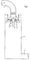
- the spray dryer shown schematically in FIG. 1 has a vertically arranged reactor housing 1, to which the gas to be cooled is supplied from above through a feed line 2. At the lower end of the reactor housing 1, the cooled gas is discharged through an outlet 3.
- the horizontally arriving, subsequently arc-shaped supply line 2 which is connected centrally from above to the reactor housing 1, opens into a funnel-shaped housing attachment 4.
- liquid is supplied to the gas stream to be cooled, which through its Evaporation causes the gas to cool.
- liquid nozzles 6 are shown schematically. Solid particles can be introduced into this liquid flow.
- This impact diffuser 7 creates a uniform pressure field in a ring around the entry of the gas into the reactor housing 1, which despite the uneven speed profile of the entering gas flow prevents lateral deflection of the gas flow and causes a central alignment of the gas flow with the longitudinal center line of the reactor housing 1.
- vortex installation surfaces 8 arranged with their surface at an acute angle to the main flow direction of the gas result in only a negligibly small reduction in the flow cross section, so that the flow losses resulting from their installation are small. In addition, such vortex installation surfaces 8 require only little construction effort.
- FIG. 4 shows a triangular vortex installation surface 8, which is arranged with its tip opposite to the main flow direction.
- the vortex installation surface 8 shown in FIG. 5 is diamond-shaped and is likewise arranged with one of its tips opposite to the direction of flow and at an acute angle to the main direction of flow in the region of the impact diffuser 7.
- 6 and 7 show the basic shape of circular or oval vortex installation surfaces 8.
- These vortex installation surfaces 8 are also arranged at an acute angle to the main direction of flow in the gas flow and, by virtue of their leading edge flowing against them, result in the formation of leading edge vortex systems.
- a stabilization of the vortex installation surfaces 8 is also achieved in that they are provided with an angled edge.
- Fig. 1 further shows that a conversion of existing spray dryer is easily possible by installing a shock diffuser 7 and vortex mounting surfaces 8 in the housing attachment 4.
- the second exemplary embodiment according to FIGS. 2 and 3 shows that it is also possible to design the impact diffuser 7 by appropriately designing the transition between the feed line 2 and the reactor housing 1.
- the rectangular transition shown in FIG. 2 between the feed line 2 and the top of the reactor housing 1 inevitably creates an impact diffuser 7, in the area of which the vortex installation surfaces 8 can be arranged.
- the cross section in FIG. 3 shows a possible arrangement for a total of four such vortex installation surfaces 8 with a triangular basic shape.
Landscapes
- Chemical & Material Sciences (AREA)
- Engineering & Computer Science (AREA)
- Chemical Kinetics & Catalysis (AREA)
- Mechanical Engineering (AREA)
- General Engineering & Computer Science (AREA)
- Dispersion Chemistry (AREA)
- Life Sciences & Earth Sciences (AREA)
- Microbiology (AREA)
- Vaporization, Distillation, Condensation, Sublimation, And Cold Traps (AREA)
- Drying Of Solid Materials (AREA)
- Devices And Processes Conducted In The Presence Of Fluids And Solid Particles (AREA)
Applications Claiming Priority (2)
| Application Number | Priority Date | Filing Date | Title |
|---|---|---|---|
| DE4325968 | 1993-08-03 | ||
| DE4325968A DE4325968C2 (de) | 1993-08-03 | 1993-08-03 | Vorrichtung zum Kühlen von Gasen und gegebenenfalls Trocknen von dem Gas zugegebenen Feststoffteilchen |
Publications (2)
| Publication Number | Publication Date |
|---|---|
| EP0637726A1 true EP0637726A1 (fr) | 1995-02-08 |
| EP0637726B1 EP0637726B1 (fr) | 1997-06-18 |
Family
ID=6494319
Family Applications (1)
| Application Number | Title | Priority Date | Filing Date |
|---|---|---|---|
| EP94111533A Expired - Lifetime EP0637726B1 (fr) | 1993-08-03 | 1994-07-23 | Dispositif de refroidissement des gaz et éventuellement pour sécher de particules solides contenus dans le gaz |
Country Status (8)
| Country | Link |
|---|---|
| US (1) | US5547540A (fr) |
| EP (1) | EP0637726B1 (fr) |
| JP (1) | JPH07167562A (fr) |
| AT (1) | ATE154691T1 (fr) |
| DE (2) | DE4325968C2 (fr) |
| DK (1) | DK0637726T3 (fr) |
| ES (1) | ES2102737T3 (fr) |
| GR (1) | GR3023909T3 (fr) |
Cited By (4)
| Publication number | Priority date | Publication date | Assignee | Title |
|---|---|---|---|---|
| WO2007073881A1 (fr) * | 2005-12-15 | 2007-07-05 | Fisia Babcock Environment Gmbh | Dispositif pour le melange d’un fluide avec une grande quantite de gaz, notamment pour introduire un reducteur dans un gaz de combustion contenant un oxyde d'azote |
| DE102004052827B4 (de) * | 2004-11-02 | 2010-05-06 | Lurgi Gmbh | Vorrichtung zur Erzeugung eines o-Xylol-Luft-Gemisches für die Phthalsäureanhydrid-Herstellung |
| US8096701B2 (en) | 2006-01-28 | 2012-01-17 | Fisia Babcock Environment Gmbh | Method and apparatus for mixing a gaseous fluid with a large gas stream, especially for introducing a reducing agent into a flue gas containing nitrogen oxides |
| US8517599B2 (en) | 2006-01-28 | 2013-08-27 | Fisia Babcock Environment Gmbh | Method and apparatus for mixing a gaseous fluid with a large gas stream, especially for introducing a reducing agent into a flue gas that contains nitrogen oxides |
Families Citing this family (24)
| Publication number | Priority date | Publication date | Assignee | Title |
|---|---|---|---|---|
| PT762837E (pt) * | 1995-03-31 | 2002-07-31 | Schur Jorg Peter | Processo para melhorar a durabilidade e/ou estabilizacao de produtos degradaveis microbiologicamente |
| DE19820992C2 (de) * | 1998-05-11 | 2003-01-09 | Bbp Environment Gmbh | Vorrichtung zur Durchmischung eines einen Kanal durchströmenden Gasstromes und Verfahren unter Verwendung der Vorrichtung |
| DE19931185A1 (de) | 1999-07-07 | 2001-01-18 | Joerg Peter Schuer | Verfahren zur Entkeimung von Luft |
| DE19940283A1 (de) * | 1999-08-25 | 2001-03-01 | Joerg Peter Schuer | Pflanzenschutz |
| DE19940605A1 (de) | 1999-08-27 | 2001-03-01 | Joerg Peter Schuer | Imprägnierungsverfahren |
| US6322054B1 (en) * | 2000-03-17 | 2001-11-27 | Chung-Hsing Wu | Sprinkling apparatus for cooling tower |
| ATE235311T1 (de) * | 2000-06-19 | 2003-04-15 | Balcke Duerr Energietech Gmbh | Mischer für die mischung mindestens zweier gasströme oder anderer newtonscher flüssigkeiten |
| DE20100121U1 (de) * | 2001-01-05 | 2002-05-16 | Schür, Jörg Peter, Prof., 41844 Wegberg | Vorrichtung zur Anreicherung von Luft mit Luftbehandlungsmittel |
| DE10100595A1 (de) * | 2001-01-09 | 2002-07-18 | Joerg Peter Schuer | Verfahren zur untoxischen Geruchsneutralisierung von Luft |
| US20030031588A1 (en) * | 2001-06-13 | 2003-02-13 | Schur Jorg Peter | Device for enriching air with an air treatment agent, especially for the disinfection of air, and/or perfuming of air and/or for odor masking |
| DE10129367A1 (de) * | 2001-06-20 | 2003-01-09 | Klingenburg Gmbh | Luftbefeuchtungsvorrichtung |
| WO2004051165A2 (fr) * | 2002-12-03 | 2004-06-17 | Lg Electronics Inc. | Mecanisme d'etalement d'ecoulement |
| KR20050076213A (ko) * | 2004-01-20 | 2005-07-26 | 삼성전자주식회사 | 의류건조기 |
| DK1568410T3 (da) | 2004-02-27 | 2010-06-14 | Haldor Topsoe As | Apparat til blanding af fluidstrømme |
| US7448794B2 (en) * | 2004-02-27 | 2008-11-11 | Haldor Topsoe A/S | Method for mixing fluid streams |
| US9295953B2 (en) * | 2004-10-01 | 2016-03-29 | Harald Linga | Multi fluid injection mixer |
| ES2285577T3 (es) * | 2005-01-17 | 2007-11-16 | Balcke-Durr Gmbh | Dispositivo y procedimiento para el mezclado de un fluido que circula en una direccion de circulacion. |
| US8010236B2 (en) * | 2007-10-30 | 2011-08-30 | Babcock Power Environmental Inc. | Adaptive control system for reagent distribution control in SCR reactors |
| CN106123559A (zh) * | 2016-07-14 | 2016-11-16 | 滨海金地矿业工程技术(北京)有限公司 | 一种煤炭干燥系统的自动快速控温装置及煤炭干燥系统 |
| US20200078757A1 (en) | 2018-09-07 | 2020-03-12 | The Procter & Gamble Company | Methods and Systems for Forming Microcapsules |
| US20200078759A1 (en) | 2018-09-07 | 2020-03-12 | The Procter & Gamble Company | Methods and Systems for Forming Microcapsules |
| US20200078758A1 (en) | 2018-09-07 | 2020-03-12 | The Procter & Gamble Company | Methods and Systems for Forming Microcapsules |
| US11833481B2 (en) | 2018-10-05 | 2023-12-05 | Produced Water Absorbents Inc. | Multi-channel, variable-flow mixers and related methods |
| US11673104B2 (en) | 2018-12-07 | 2023-06-13 | Produced Water Absorbents Inc. | Multi-fluid injection mixer and related methods |
Citations (3)
| Publication number | Priority date | Publication date | Assignee | Title |
|---|---|---|---|---|
| FR1163735A (fr) * | 1956-12-04 | 1958-09-30 | Afico Sa | Perfectionnements aux appareils dessicateurs |
| US4187617A (en) * | 1978-12-18 | 1980-02-12 | Becker James J Jr | Spray dryer |
| DE3229843A1 (de) * | 1981-08-26 | 1983-03-24 | Combustion Engineering, Inc., 06095 Windsor, Conn. | Zerstaeubungskopfanordnung fuer zerstaeubungstrockner |
Family Cites Families (6)
| Publication number | Priority date | Publication date | Assignee | Title |
|---|---|---|---|---|
| US4571311A (en) * | 1985-01-22 | 1986-02-18 | Combustion Engineering, Inc. | Apparatus for introducing a process gas into a treatment chamber |
| FR2583652B1 (fr) * | 1985-06-21 | 1989-10-27 | Air Ind Environnement | Perfectionnement aux tours de refroidissement des gaz charges de poussieres |
| US5232550A (en) * | 1987-04-27 | 1993-08-03 | Ohkawara Kakohki Co., Ltd. | Vacuum drying method |
| ATE68986T1 (de) * | 1987-07-03 | 1991-11-15 | Ciba Geigy Ag | Spruehtrockner zur herstellung von pulvern, agglomeraten oder dergleichen. |
| US5227017A (en) * | 1988-01-29 | 1993-07-13 | Ohkawara Kakohki Co., Ltd. | Spray drying apparatus equipped with a spray nozzle unit |
| DE4112750A1 (de) * | 1991-04-19 | 1992-10-22 | Balcke Duerr Ag | Verfahren und vorrichtung zur erhoehung der abscheideleistung von rauchgas-entschwefelungs-anlagen |
-
1993
- 1993-08-03 DE DE4325968A patent/DE4325968C2/de not_active Expired - Fee Related
-
1994
- 1994-07-23 DE DE59403162T patent/DE59403162D1/de not_active Expired - Lifetime
- 1994-07-23 ES ES94111533T patent/ES2102737T3/es not_active Expired - Lifetime
- 1994-07-23 DK DK94111533.9T patent/DK0637726T3/da active
- 1994-07-23 EP EP94111533A patent/EP0637726B1/fr not_active Expired - Lifetime
- 1994-07-23 AT AT94111533T patent/ATE154691T1/de active
- 1994-08-02 JP JP6210335A patent/JPH07167562A/ja active Pending
- 1994-08-03 US US08/286,487 patent/US5547540A/en not_active Expired - Lifetime
-
1997
- 1997-06-26 GR GR970401557T patent/GR3023909T3/el unknown
Patent Citations (3)
| Publication number | Priority date | Publication date | Assignee | Title |
|---|---|---|---|---|
| FR1163735A (fr) * | 1956-12-04 | 1958-09-30 | Afico Sa | Perfectionnements aux appareils dessicateurs |
| US4187617A (en) * | 1978-12-18 | 1980-02-12 | Becker James J Jr | Spray dryer |
| DE3229843A1 (de) * | 1981-08-26 | 1983-03-24 | Combustion Engineering, Inc., 06095 Windsor, Conn. | Zerstaeubungskopfanordnung fuer zerstaeubungstrockner |
Cited By (6)
| Publication number | Priority date | Publication date | Assignee | Title |
|---|---|---|---|---|
| DE102004052827B4 (de) * | 2004-11-02 | 2010-05-06 | Lurgi Gmbh | Vorrichtung zur Erzeugung eines o-Xylol-Luft-Gemisches für die Phthalsäureanhydrid-Herstellung |
| WO2007073881A1 (fr) * | 2005-12-15 | 2007-07-05 | Fisia Babcock Environment Gmbh | Dispositif pour le melange d’un fluide avec une grande quantite de gaz, notamment pour introduire un reducteur dans un gaz de combustion contenant un oxyde d'azote |
| RU2389537C2 (ru) * | 2005-12-15 | 2010-05-20 | Физиа Бэбкок Инвайромент Гмбх | Устройство для смешивания текучей среды с большим объемным потоком газа, в частности, для введения восстановителя в содержащий оксиды азота дымовой газ |
| US8033531B2 (en) | 2005-12-15 | 2011-10-11 | Fisia Babcock Environment Gmbh | Apparatus for mixing a fluid with a large gas stream, especially for introducing a reducing agent into a flue gas containing nitrogen oxides |
| US8096701B2 (en) | 2006-01-28 | 2012-01-17 | Fisia Babcock Environment Gmbh | Method and apparatus for mixing a gaseous fluid with a large gas stream, especially for introducing a reducing agent into a flue gas containing nitrogen oxides |
| US8517599B2 (en) | 2006-01-28 | 2013-08-27 | Fisia Babcock Environment Gmbh | Method and apparatus for mixing a gaseous fluid with a large gas stream, especially for introducing a reducing agent into a flue gas that contains nitrogen oxides |
Also Published As
| Publication number | Publication date |
|---|---|
| DK0637726T3 (da) | 1998-01-26 |
| US5547540A (en) | 1996-08-20 |
| GR3023909T3 (en) | 1997-09-30 |
| ES2102737T3 (es) | 1997-08-01 |
| ATE154691T1 (de) | 1997-07-15 |
| DE4325968A1 (de) | 1995-02-09 |
| DE59403162D1 (de) | 1997-07-24 |
| EP0637726B1 (fr) | 1997-06-18 |
| JPH07167562A (ja) | 1995-07-04 |
| DE4325968C2 (de) | 1997-04-10 |
Similar Documents
| Publication | Publication Date | Title |
|---|---|---|
| EP0637726B1 (fr) | Dispositif de refroidissement des gaz et éventuellement pour sécher de particules solides contenus dans le gaz | |
| DE69629276T2 (de) | Flachstrahldüse | |
| EP0433790B1 (fr) | Brûleur | |
| DE3728557C2 (fr) | ||
| DE10304386B4 (de) | Doppelfluid-Verwirbelungsdüse mit selbstreinigendem Zapfen | |
| DE60319273T2 (de) | Entzunderungsdüse | |
| DE69115047T2 (de) | Zerstäubungsdüse. | |
| DE3131070A1 (de) | "spruehduese mit hohem wirkungsgrad" | |
| EP0076472A1 (fr) | Dispositif pour la distribution uniforme d'un courant d'une matière en vrac | |
| EP0429942B1 (fr) | Appareil pour l'échange d'une matière entre un courant gazeux chaud et un liquide | |
| DE69324705T2 (de) | Dampfkühler | |
| DE2417355A1 (de) | Zentrifugaldruckduese | |
| WO1999033554A1 (fr) | Dispositif permettant de melanger puis de pulveriser des liquides | |
| DE1906895A1 (de) | Verfahren und Vorrichtung zur direkten Heizung von Wirbelschichtreaktoren | |
| DE3815211C2 (fr) | ||
| DE2648445A1 (de) | Flachstrahler fuer ein gemisch einer druckfluessigkeit mit feststoffteilchen | |
| DE2711726C2 (de) | Vorrichtung zum Zerstäuben einer Flüssigkeit, insbesondere für die Melaminherstellung und die Harnstoffgranulatherstellung | |
| DE3541599A1 (de) | Verfahren und vorrichtung zum beimischen einer zerstaeubten fluessigkeit in einen gasstrom | |
| EP0352342B1 (fr) | Brûleur pour des procédés de séchage ou de purification de gaz | |
| CH629394A5 (de) | Ringspaltduese. | |
| DE3004864A1 (de) | Vorrichtung zum aufspruehen eines kuehlmittels auf stahlbrammen | |
| DE2933720A1 (de) | Fluessigkeitsverteilvorrichtung fuer kuehltuerme | |
| DE2149445A1 (de) | Leitvorrichtung fuer Brenner | |
| DE8900464U1 (de) | Dampfkühleinrichtung | |
| DE3688127T2 (de) | Atomisierungsvorrichtung. |
Legal Events
| Date | Code | Title | Description |
|---|---|---|---|
| PUAI | Public reference made under article 153(3) epc to a published international application that has entered the european phase |
Free format text: ORIGINAL CODE: 0009012 |
|
| AK | Designated contracting states |
Kind code of ref document: A1 Designated state(s): AT BE CH DE DK ES FR GB GR IE IT LI LU NL PT SE |
|
| 17P | Request for examination filed |
Effective date: 19950114 |
|
| 17Q | First examination report despatched |
Effective date: 19960110 |
|
| GRAG | Despatch of communication of intention to grant |
Free format text: ORIGINAL CODE: EPIDOS AGRA |
|
| GRAH | Despatch of communication of intention to grant a patent |
Free format text: ORIGINAL CODE: EPIDOS IGRA |
|
| GRAH | Despatch of communication of intention to grant a patent |
Free format text: ORIGINAL CODE: EPIDOS IGRA |
|
| GRAA | (expected) grant |
Free format text: ORIGINAL CODE: 0009210 |
|
| RAP1 | Party data changed (applicant data changed or rights of an application transferred) |
Owner name: DEUTSCHE BABCOCK ANLAGEN GMBH |
|
| AK | Designated contracting states |
Kind code of ref document: B1 Designated state(s): AT BE CH DE DK ES FR GB GR IE IT LI LU NL PT SE |
|
| REF | Corresponds to: |
Ref document number: 154691 Country of ref document: AT Date of ref document: 19970715 Kind code of ref document: T |
|
| REG | Reference to a national code |
Ref country code: CH Ref legal event code: EP |
|
| GBT | Gb: translation of ep patent filed (gb section 77(6)(a)/1977) |
Effective date: 19970619 |
|
| ET | Fr: translation filed | ||
| REF | Corresponds to: |
Ref document number: 59403162 Country of ref document: DE Date of ref document: 19970724 |
|
| PG25 | Lapsed in a contracting state [announced via postgrant information from national office to epo] |
Ref country code: LU Free format text: LAPSE BECAUSE OF NON-PAYMENT OF DUE FEES Effective date: 19970731 |
|
| REG | Reference to a national code |
Ref country code: ES Ref legal event code: FG2A Ref document number: 2102737 Country of ref document: ES Kind code of ref document: T3 |
|
| REG | Reference to a national code |
Ref country code: GR Ref legal event code: FG4A Free format text: 3023909 |
|
| ITF | It: translation for a ep patent filed | ||
| PG25 | Lapsed in a contracting state [announced via postgrant information from national office to epo] |
Ref country code: SE Effective date: 19970918 Ref country code: PT Effective date: 19970918 |
|
| REG | Reference to a national code |
Ref country code: DK Ref legal event code: T3 |
|
| REG | Reference to a national code |
Ref country code: IE Ref legal event code: FD4D Ref document number: 74771 Country of ref document: IE |
|
| PLBE | No opposition filed within time limit |
Free format text: ORIGINAL CODE: 0009261 |
|
| STAA | Information on the status of an ep patent application or granted ep patent |
Free format text: STATUS: NO OPPOSITION FILED WITHIN TIME LIMIT |
|
| 26N | No opposition filed | ||
| PGFP | Annual fee paid to national office [announced via postgrant information from national office to epo] |
Ref country code: CH Payment date: 20000616 Year of fee payment: 7 |
|
| PGFP | Annual fee paid to national office [announced via postgrant information from national office to epo] |
Ref country code: NL Payment date: 20000620 Year of fee payment: 7 |
|
| PGFP | Annual fee paid to national office [announced via postgrant information from national office to epo] |
Ref country code: GR Payment date: 20000630 Year of fee payment: 7 |
|
| PGFP | Annual fee paid to national office [announced via postgrant information from national office to epo] |
Ref country code: BE Payment date: 20000704 Year of fee payment: 7 |
|
| PGFP | Annual fee paid to national office [announced via postgrant information from national office to epo] |
Ref country code: ES Payment date: 20000720 Year of fee payment: 7 |
|
| PGFP | Annual fee paid to national office [announced via postgrant information from national office to epo] |
Ref country code: GB Payment date: 20010614 Year of fee payment: 8 |
|
| PG25 | Lapsed in a contracting state [announced via postgrant information from national office to epo] |
Ref country code: ES Free format text: LAPSE BECAUSE OF NON-PAYMENT OF DUE FEES Effective date: 20010724 |
|
| PG25 | Lapsed in a contracting state [announced via postgrant information from national office to epo] |
Ref country code: LI Free format text: LAPSE BECAUSE OF NON-PAYMENT OF DUE FEES Effective date: 20010731 Ref country code: GR Free format text: LAPSE BECAUSE OF NON-PAYMENT OF DUE FEES Effective date: 20010731 Ref country code: CH Free format text: LAPSE BECAUSE OF NON-PAYMENT OF DUE FEES Effective date: 20010731 Ref country code: BE Free format text: LAPSE BECAUSE OF NON-PAYMENT OF DUE FEES Effective date: 20010731 |
|
| REG | Reference to a national code |
Ref country code: GB Ref legal event code: IF02 |
|
| BERE | Be: lapsed |
Owner name: DEUTSCHE BABCOCK ANLAGEN G.M.B.H. Effective date: 20010731 |
|
| PG25 | Lapsed in a contracting state [announced via postgrant information from national office to epo] |
Ref country code: NL Free format text: LAPSE BECAUSE OF NON-PAYMENT OF DUE FEES Effective date: 20020201 |
|
| REG | Reference to a national code |
Ref country code: CH Ref legal event code: PL |
|
| NLV4 | Nl: lapsed or anulled due to non-payment of the annual fee |
Effective date: 20020201 |
|
| PG25 | Lapsed in a contracting state [announced via postgrant information from national office to epo] |
Ref country code: GB Free format text: LAPSE BECAUSE OF NON-PAYMENT OF DUE FEES Effective date: 20020723 |
|
| GBPC | Gb: european patent ceased through non-payment of renewal fee |
Effective date: 20020723 |
|
| REG | Reference to a national code |
Ref country code: ES Ref legal event code: FD2A Effective date: 20020810 |
|
| REG | Reference to a national code |
Ref country code: FR Ref legal event code: TP Ref country code: FR Ref legal event code: CD Ref country code: FR Ref legal event code: CA |
|
| PGFP | Annual fee paid to national office [announced via postgrant information from national office to epo] |
Ref country code: DK Payment date: 20110720 Year of fee payment: 18 |
|
| PGFP | Annual fee paid to national office [announced via postgrant information from national office to epo] |
Ref country code: FR Payment date: 20120806 Year of fee payment: 19 Ref country code: DE Payment date: 20120713 Year of fee payment: 19 Ref country code: IT Payment date: 20120727 Year of fee payment: 19 |
|
| PGFP | Annual fee paid to national office [announced via postgrant information from national office to epo] |
Ref country code: AT Payment date: 20120711 Year of fee payment: 19 |
|
| REG | Reference to a national code |
Ref country code: DK Ref legal event code: EBP Effective date: 20130731 |
|
| REG | Reference to a national code |
Ref country code: AT Ref legal event code: MM01 Ref document number: 154691 Country of ref document: AT Kind code of ref document: T Effective date: 20130723 |
|
| REG | Reference to a national code |
Ref country code: FR Ref legal event code: ST Effective date: 20140331 |
|
| PG25 | Lapsed in a contracting state [announced via postgrant information from national office to epo] |
Ref country code: DE Free format text: LAPSE BECAUSE OF NON-PAYMENT OF DUE FEES Effective date: 20140201 |
|
| REG | Reference to a national code |
Ref country code: DE Ref legal event code: R119 Ref document number: 59403162 Country of ref document: DE Effective date: 20140201 |
|
| PG25 | Lapsed in a contracting state [announced via postgrant information from national office to epo] |
Ref country code: IT Free format text: LAPSE BECAUSE OF NON-PAYMENT OF DUE FEES Effective date: 20130723 Ref country code: AT Free format text: LAPSE BECAUSE OF NON-PAYMENT OF DUE FEES Effective date: 20130723 Ref country code: FR Free format text: LAPSE BECAUSE OF NON-PAYMENT OF DUE FEES Effective date: 20130731 |
|
| PG25 | Lapsed in a contracting state [announced via postgrant information from national office to epo] |
Ref country code: DK Free format text: LAPSE BECAUSE OF NON-PAYMENT OF DUE FEES Effective date: 20130731 |