EP0637092A1 - Elektrische Batterie - Google Patents
Elektrische Batterie Download PDFInfo
- Publication number
- EP0637092A1 EP0637092A1 EP94109532A EP94109532A EP0637092A1 EP 0637092 A1 EP0637092 A1 EP 0637092A1 EP 94109532 A EP94109532 A EP 94109532A EP 94109532 A EP94109532 A EP 94109532A EP 0637092 A1 EP0637092 A1 EP 0637092A1
- Authority
- EP
- European Patent Office
- Prior art keywords
- cells
- positive
- negative
- electrodes
- active paste
- Prior art date
- Legal status (The legal status is an assumption and is not a legal conclusion. Google has not performed a legal analysis and makes no representation as to the accuracy of the status listed.)
- Granted
Links
Images

Classifications
-
- H—ELECTRICITY
- H01—ELECTRIC ELEMENTS
- H01M—PROCESSES OR MEANS, e.g. BATTERIES, FOR THE DIRECT CONVERSION OF CHEMICAL ENERGY INTO ELECTRICAL ENERGY
- H01M10/00—Secondary cells; Manufacture thereof
- H01M10/04—Construction or manufacture in general
- H01M10/0413—Large-sized flat cells or batteries for motive or stationary systems with plate-like electrodes
- H01M10/0418—Large-sized flat cells or batteries for motive or stationary systems with plate-like electrodes with bipolar electrodes
-
- H—ELECTRICITY
- H01—ELECTRIC ELEMENTS
- H01M—PROCESSES OR MEANS, e.g. BATTERIES, FOR THE DIRECT CONVERSION OF CHEMICAL ENERGY INTO ELECTRICAL ENERGY
- H01M10/00—Secondary cells; Manufacture thereof
- H01M10/06—Lead-acid accumulators
-
- Y—GENERAL TAGGING OF NEW TECHNOLOGICAL DEVELOPMENTS; GENERAL TAGGING OF CROSS-SECTIONAL TECHNOLOGIES SPANNING OVER SEVERAL SECTIONS OF THE IPC; TECHNICAL SUBJECTS COVERED BY FORMER USPC CROSS-REFERENCE ART COLLECTIONS [XRACs] AND DIGESTS
- Y02—TECHNOLOGIES OR APPLICATIONS FOR MITIGATION OR ADAPTATION AGAINST CLIMATE CHANGE
- Y02E—REDUCTION OF GREENHOUSE GAS [GHG] EMISSIONS, RELATED TO ENERGY GENERATION, TRANSMISSION OR DISTRIBUTION
- Y02E60/00—Enabling technologies; Technologies with a potential or indirect contribution to GHG emissions mitigation
- Y02E60/10—Energy storage using batteries
-
- Y—GENERAL TAGGING OF NEW TECHNOLOGICAL DEVELOPMENTS; GENERAL TAGGING OF CROSS-SECTIONAL TECHNOLOGIES SPANNING OVER SEVERAL SECTIONS OF THE IPC; TECHNICAL SUBJECTS COVERED BY FORMER USPC CROSS-REFERENCE ART COLLECTIONS [XRACs] AND DIGESTS
- Y02—TECHNOLOGIES OR APPLICATIONS FOR MITIGATION OR ADAPTATION AGAINST CLIMATE CHANGE
- Y02P—CLIMATE CHANGE MITIGATION TECHNOLOGIES IN THE PRODUCTION OR PROCESSING OF GOODS
- Y02P70/00—Climate change mitigation technologies in the production process for final industrial or consumer products
- Y02P70/50—Manufacturing or production processes characterised by the final manufactured product
Definitions
- the present invention relates to an electrical battery comprising a container which contains at least two cells disposed electrically in series and each including two electrodes, a positive and a negative respectively, separated by a partition, each electrode being constituted by at least one grid of electrically conductive material adapted to support a positive or negative active paste respectively.
- connection may be broken in various ways: for example, improper welding or corrosion thereof due to the generation of localised cells.
- a subject of the present invention is a battery of the type indicated above characterised in that at least one negative electrode and one positive electrode of two different cells are formed with the use of the same grid, different portions of which support the positive active paste and the negative active paste respectively.
- the electrical connection between electrodes of opposite polarity in adjacent cells is achieved by virtue of the said grid of conductive material, different portions of which act as the negative electrode and the positive electrode respectively.
- the battery according to the invention has the further advantage of having a compact structure which does not require additional elements to ensure the interconnection of the various cells, with a simplification in the process for its production.
- this latter comprises first and second adjacent cells.
- the first and second cells include a first positive electrode and a first negative electrode respectively having terminals for connection to external circuits.
- a grid which has two separate portions which support positive and negative active pastes respectively is superposed on the first positive and negative electrodes so that the portion which supports the positive active paste is opposite the first negative electrode, constituting the positive electrode of the second cell, and the portion which supports the negative active paste is opposite the first positive electrode, constituting the negative electrode of the first cell.
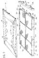
- An electrical battery comprises ( Figures 1 to 3) a container 10 formed by a box-shaped housing 12 without two faces which are closed by a cover 14 and a side element 16 respectively which latter supports a positive pole 18a and a negative pole 18b for enabling the battery to be connected to external circuits.
- the container 10 Within the container 10 are six cells 20a - 20f arranged in a matrix constituted by two rows and three columns.
- Each cell 20 includes a positive electrode 22 located opposite a negative electrode 24, a partition 26 being located between them, and a free or immobilised electrolyte not visible in the drawings.
- the cell may be filled with the electrolyte through apertures 28 ( Figure 3) formed in the cover 14 in correspondence with each cell 20.
- the electrodes 22, 24 of the cells 20 are arranged in first and second parallel planes 30, 32 respectively in such a manner that the electrodes 22, 24 of different polarity lie in a chequered array in each plane 30, 32.
- the two cells 20c, 20d in the end column of the matrix alongside the side element 16 in the first plane 30 have a first positive electrode 22c and a first negative electrode 24d with terminals 34a, 34b for their connection to the poles 18 ( Figure 3).
- Electrodes 22c, 24d are formed in known manner by a grid structure, for example of lead alloy, which supports an active paste.
- the two remaining pairs of cells 20a, 20b; 20e, 20f of each row of the matrix have respective grids 36a, 36b of conductive material, particularly lead alloy, similar to that used for the electrodes 22c, 24d.
- Separate portions 38a, 38b of the grids 36 support a positive active paste and a negative active paste respectively constituting further positive electrodes 22a, 22e and negative electrodes 24b, 24f respectively.
- the pair of cells 20a, 20f of the end column opposite the end column containing the cells 20c, 20d with the first positive electrode 22c and negative electrode 24d and the two remaining pairs of cells 20b, 20c; 20d, 20e of each row of the matrix include further respective grids 36c, 36d, 36e coated with active paste in a manner similar to those located in the first plane 30.
- the various cells 20 are insulated from each other by means of respective beads 40 of insulating material, for example resin, disposed between the two portions 38 of each grid 36 and in the interstices between adjacent cells 20.
- respective beads 40 of insulating material for example resin
- a wall 42 which has the further function of stiffening the container 10 and which projects upwardly between the two rows of cells 20 in correspondence with the central column and the end column close to the side element 16.
- the grids 36 act as electrical connection means between the two electrodes 22, 24 of opposite polarity formed on each grid 36 and thus connect the two different cells 20 to which the electrodes 22, 24 belong in series.
- the six cells 20 are thus connected in series with each other so that the overall voltage supplied by the battery is given by the sum of the voltages of the individual cells 20.
- the method of manufacture of the battery of the invention includes the deposition of insulating beads 40a, 40b on the bottom of the container and then the positioning of the electrodes 22c, 24d and the grids 36a, 36b of the first plane 30, coated with the active material, on the beads in the first plane 30. Then ( Figure 2) the insulating beads 40c, 40d, 40e are deposited and the partitions 26 are positioned on the electrodes 22, 24 of the first plane 30 and the grids 36c, 36d, 36e of the second plane 32, coated with active material, are positioned on the partitions 26.
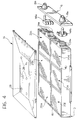
- FIG. 4 illustrates a further embodiment of a battery according to the invention in which corresponding or equivalent parts to those used above are indicated by the same reference numerals.
- a plurality of elementary units each constituted by six cells 20 arranged in a matrix similar to that described above are superposed in a pack within the container 10.
- Respective connecting elements 44a, 44b interconnect the terminals 34a, 34b of the same polarity and connect them to a respective pole 18a, 18b projecting from the container 10.
Applications Claiming Priority (2)
| Application Number | Priority Date | Filing Date | Title |
|---|---|---|---|
| ITTO930520A IT1270458B (it) | 1993-07-13 | 1993-07-13 | Accumulatore elettrico. |
| ITTO930520 | 1993-07-13 |
Publications (2)
| Publication Number | Publication Date |
|---|---|
| EP0637092A1 true EP0637092A1 (de) | 1995-02-01 |
| EP0637092B1 EP0637092B1 (de) | 1997-03-12 |
Family
ID=11411622
Family Applications (1)
| Application Number | Title | Priority Date | Filing Date |
|---|---|---|---|
| EP94109532A Expired - Lifetime EP0637092B1 (de) | 1993-07-13 | 1994-06-21 | Elektrische Batterie |
Country Status (5)
| Country | Link |
|---|---|
| EP (1) | EP0637092B1 (de) |
| AT (1) | ATE150215T1 (de) |
| DE (1) | DE69402005T2 (de) |
| ES (1) | ES2100599T3 (de) |
| IT (1) | IT1270458B (de) |
Citations (7)
| Publication number | Priority date | Publication date | Assignee | Title |
|---|---|---|---|---|
| FR2292345A1 (fr) * | 1974-11-25 | 1976-06-18 | Dunlop Australia Ltd | Batterie d'accumulateur a elements multiples |
| JPS5787081A (en) * | 1980-11-19 | 1982-05-31 | Yuasa Battery Co Ltd | Lead-acid battery |
| JPS5790882A (en) * | 1980-11-26 | 1982-06-05 | Shin Kobe Electric Mach Co Ltd | Manufacture of lead battery |
| EP0107976A2 (de) * | 1982-10-29 | 1984-05-09 | Chloride Group Public Limited Company | Mehrzellige elektrische Speicherbatterien |
| GB2158285A (en) * | 1984-05-01 | 1985-11-06 | Chloride Group Plc | Multicell electric storage batteries |
| EP0239051A1 (de) * | 1986-03-25 | 1987-09-30 | Neste Oy | Verfahren und Vorrichtung zur Anordnung von Sekundärbatterieplatten |
| WO1989012329A1 (en) * | 1988-06-01 | 1989-12-14 | Electrosource, Inc. | Lead-acid rechargeable storage battery |
-
1993
- 1993-07-13 IT ITTO930520A patent/IT1270458B/it active IP Right Grant
-
1994
- 1994-06-21 ES ES94109532T patent/ES2100599T3/es not_active Expired - Lifetime
- 1994-06-21 DE DE69402005T patent/DE69402005T2/de not_active Expired - Fee Related
- 1994-06-21 EP EP94109532A patent/EP0637092B1/de not_active Expired - Lifetime
- 1994-06-21 AT AT94109532T patent/ATE150215T1/de not_active IP Right Cessation
Patent Citations (7)
| Publication number | Priority date | Publication date | Assignee | Title |
|---|---|---|---|---|
| FR2292345A1 (fr) * | 1974-11-25 | 1976-06-18 | Dunlop Australia Ltd | Batterie d'accumulateur a elements multiples |
| JPS5787081A (en) * | 1980-11-19 | 1982-05-31 | Yuasa Battery Co Ltd | Lead-acid battery |
| JPS5790882A (en) * | 1980-11-26 | 1982-06-05 | Shin Kobe Electric Mach Co Ltd | Manufacture of lead battery |
| EP0107976A2 (de) * | 1982-10-29 | 1984-05-09 | Chloride Group Public Limited Company | Mehrzellige elektrische Speicherbatterien |
| GB2158285A (en) * | 1984-05-01 | 1985-11-06 | Chloride Group Plc | Multicell electric storage batteries |
| EP0239051A1 (de) * | 1986-03-25 | 1987-09-30 | Neste Oy | Verfahren und Vorrichtung zur Anordnung von Sekundärbatterieplatten |
| WO1989012329A1 (en) * | 1988-06-01 | 1989-12-14 | Electrosource, Inc. | Lead-acid rechargeable storage battery |
Non-Patent Citations (2)
| Title |
|---|
| PATENT ABSTRACTS OF JAPAN vol. 6, no. 170 (E - 128) 3 September 1982 (1982-09-03) * |
| PATENT ABSTRACTS OF JAPAN vol. 6, no. 173 (E - 129) 7 September 1982 (1982-09-07) * |
Also Published As
| Publication number | Publication date |
|---|---|
| IT1270458B (it) | 1997-05-05 |
| EP0637092B1 (de) | 1997-03-12 |
| ES2100599T3 (es) | 1997-06-16 |
| ATE150215T1 (de) | 1997-03-15 |
| DE69402005D1 (de) | 1997-04-17 |
| ITTO930520A0 (it) | 1993-07-13 |
| ITTO930520A1 (it) | 1995-01-13 |
| DE69402005T2 (de) | 1997-07-10 |
Similar Documents
| Publication | Publication Date | Title |
|---|---|---|
| KR20010040917A (ko) | 복합 상호연결된 축전지 망 | |
| US2905738A (en) | Battery electrode structure | |
| JP7149538B2 (ja) | 電池モジュール | |
| US5549981A (en) | Electrochemical storage device | |
| CN113937430A (zh) | 电芯信息采集结构、电池包和电池系统 | |
| EP0442599B1 (de) | Elektrochemische Batterien | |
| KR20210078139A (ko) | 복수의 단위 모듈과 bms 어셈블리를 포함하는 서브 팩 및 이를 포함하는 배터리 팩 | |
| US2515204A (en) | Storage battery plate | |
| US3846174A (en) | Proportioned current battery | |
| EP0637092B1 (de) | Elektrische Batterie | |
| JP4052421B2 (ja) | 組電池 | |
| KR20180026945A (ko) | 배터리 모듈 및 이를 포함하는 배터리 팩 | |
| US3650833A (en) | Multicell storage battery | |
| KR102511924B1 (ko) | 배터리 팩 | |
| US4328293A (en) | Electrochemical generators | |
| JP2019212561A (ja) | 蓄電装置及び組電池 | |
| US11563257B2 (en) | Structurally cross-tied energy cell | |
| US20210151810A1 (en) | Multi-tab battery cycle life extension through alternating electrode charging | |
| US20210151730A1 (en) | Full perimeter electrode cell | |
| US5128221A (en) | Storage battery | |
| US4471035A (en) | Electrochemical battery | |
| KR20100000884A (ko) | 전지셀 접속부재 | |
| CN217719795U (zh) | 一种电池模组及电池包 | |
| CN111668436B (zh) | 高功率铅蓄电池 | |
| JPH08115741A (ja) | 電池モジュール |
Legal Events
| Date | Code | Title | Description |
|---|---|---|---|
| PUAI | Public reference made under article 153(3) epc to a published international application that has entered the european phase |
Free format text: ORIGINAL CODE: 0009012 |
|
| AK | Designated contracting states |
Kind code of ref document: A1 Designated state(s): AT CH DE ES FR GB LI SE |
|
| 17P | Request for examination filed |
Effective date: 19950712 |
|
| 17Q | First examination report despatched |
Effective date: 19951123 |
|
| GRAG | Despatch of communication of intention to grant |
Free format text: ORIGINAL CODE: EPIDOS AGRA |
|
| GRAH | Despatch of communication of intention to grant a patent |
Free format text: ORIGINAL CODE: EPIDOS IGRA |
|
| RAP1 | Party data changed (applicant data changed or rights of an application transferred) |
Owner name: SOCIETA' INDUSTRIALE ACCUMULATORI S.R.L. |
|
| GRAH | Despatch of communication of intention to grant a patent |
Free format text: ORIGINAL CODE: EPIDOS IGRA |
|
| GRAA | (expected) grant |
Free format text: ORIGINAL CODE: 0009210 |
|
| AK | Designated contracting states |
Kind code of ref document: B1 Designated state(s): AT CH DE ES FR GB LI SE |
|
| PG25 | Lapsed in a contracting state [announced via postgrant information from national office to epo] |
Ref country code: LI Effective date: 19970312 Ref country code: CH Effective date: 19970312 Ref country code: AT Effective date: 19970312 |
|
| REF | Corresponds to: |
Ref document number: 150215 Country of ref document: AT Date of ref document: 19970315 Kind code of ref document: T |
|
| REG | Reference to a national code |
Ref country code: CH Ref legal event code: EP |
|
| REF | Corresponds to: |
Ref document number: 69402005 Country of ref document: DE Date of ref document: 19970417 |
|
| ET | Fr: translation filed | ||
| PG25 | Lapsed in a contracting state [announced via postgrant information from national office to epo] |
Ref country code: SE Effective date: 19970612 |
|
| REG | Reference to a national code |
Ref country code: ES Ref legal event code: FG2A Ref document number: 2100599 Country of ref document: ES Kind code of ref document: T3 |
|
| REG | Reference to a national code |
Ref country code: CH Ref legal event code: PL |
|
| PLBE | No opposition filed within time limit |
Free format text: ORIGINAL CODE: 0009261 |
|
| STAA | Information on the status of an ep patent application or granted ep patent |
Free format text: STATUS: NO OPPOSITION FILED WITHIN TIME LIMIT |
|
| 26N | No opposition filed | ||
| REG | Reference to a national code |
Ref country code: GB Ref legal event code: IF02 |
|
| PGFP | Annual fee paid to national office [announced via postgrant information from national office to epo] |
Ref country code: ES Payment date: 20030508 Year of fee payment: 10 |
|
| PGFP | Annual fee paid to national office [announced via postgrant information from national office to epo] |
Ref country code: GB Payment date: 20030516 Year of fee payment: 10 |
|
| PGFP | Annual fee paid to national office [announced via postgrant information from national office to epo] |
Ref country code: DE Payment date: 20030527 Year of fee payment: 10 |
|
| PGFP | Annual fee paid to national office [announced via postgrant information from national office to epo] |
Ref country code: FR Payment date: 20030630 Year of fee payment: 10 |
|
| PG25 | Lapsed in a contracting state [announced via postgrant information from national office to epo] |
Ref country code: GB Free format text: LAPSE BECAUSE OF NON-PAYMENT OF DUE FEES Effective date: 20040621 |
|
| PG25 | Lapsed in a contracting state [announced via postgrant information from national office to epo] |
Ref country code: ES Free format text: LAPSE BECAUSE OF NON-PAYMENT OF DUE FEES Effective date: 20040622 |
|
| PG25 | Lapsed in a contracting state [announced via postgrant information from national office to epo] |
Ref country code: DE Free format text: LAPSE BECAUSE OF NON-PAYMENT OF DUE FEES Effective date: 20050101 |
|
| GBPC | Gb: european patent ceased through non-payment of renewal fee |
Effective date: 20040621 |
|
| PG25 | Lapsed in a contracting state [announced via postgrant information from national office to epo] |
Ref country code: FR Free format text: LAPSE BECAUSE OF NON-PAYMENT OF DUE FEES Effective date: 20050228 |
|
| REG | Reference to a national code |
Ref country code: FR Ref legal event code: ST |
|
| REG | Reference to a national code |
Ref country code: ES Ref legal event code: FD2A Effective date: 20040622 |