EP0636841A2 - Coupure automatique pour brûleur à gaz - Google Patents
Coupure automatique pour brûleur à gaz Download PDFInfo
- Publication number
- EP0636841A2 EP0636841A2 EP94202033A EP94202033A EP0636841A2 EP 0636841 A2 EP0636841 A2 EP 0636841A2 EP 94202033 A EP94202033 A EP 94202033A EP 94202033 A EP94202033 A EP 94202033A EP 0636841 A2 EP0636841 A2 EP 0636841A2
- Authority
- EP
- European Patent Office
- Prior art keywords
- burner
- gas
- gas burner
- sensor
- professional
- Prior art date
- Legal status (The legal status is an assumption and is not a legal conclusion. Google has not performed a legal analysis and makes no representation as to the accuracy of the status listed.)
- Withdrawn
Links
Images
Classifications
-
- F—MECHANICAL ENGINEERING; LIGHTING; HEATING; WEAPONS; BLASTING
- F24—HEATING; RANGES; VENTILATING
- F24C—DOMESTIC STOVES OR RANGES ; DETAILS OF DOMESTIC STOVES OR RANGES, OF GENERAL APPLICATION
- F24C3/00—Stoves or ranges for gaseous fuels
- F24C3/12—Arrangement or mounting of control or safety devices
- F24C3/126—Arrangement or mounting of control or safety devices on ranges
Definitions
- the invention constitutes a perfecting and innovative mechanism for the use of gas burners used especially in industrial type kitchens, restaurants, hotels, hospitals and other large food supply services.
- the invention consists of an assembly of different elements known in the art, however, implying a new inventive result.
- the senor By placing a frying pan, a saucepan, a pot (etc, ...) on the burner, the sensor electrically triggers the opening of the gas valve (electronically directed) specially installed, so that the burner lights up.
- the system also offers maximum security.
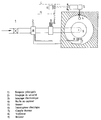
- the figure shows the traditional operating system of a gas burner (points 1, 2, 7, 8, 9) to which will be added an improvement system consisting of the present invention.
- the traditional gas burner system consists of a main line (1), a safety valve in combination with a pilot light with thermocouple (7,8), and the burner itself (9).
- the inventor adapts to this traditional functional system an assembly composed of a sensory element (5), a connecting rod or a sensor (4) to trigger the sensor, an electric / electronic valve (3) incorporated in the gas pipe, as well as the connection of the invention to the electrical circuit.
- the sensory element and the triggering sensor relating thereto may consist of an inductive, electrostatic, magnetic, electro-optical or even reactive system to sound.
- the valve can be of the "SOLANOID" type and the size depends on the size of the burner gas tubes.
- the system can be functional from an electrical circuit of 24V or 220V AC, otherwise 24V DC.
Abstract
Description
- L'invention constitue un mécanisme perfectionneur et innovateur pour l'utilisation des brûleurs à gaz utilisés surtout dans des cuisines de type industrie, restauration, hôtel, hôpital et autres services d'approvisionnement alimentaire de grande taille.
- Dans le domaine technique des cuisinières à gaz de type professionnel, on connaît le seul interrupteur de gaz principal et traditionnel, devant être utilisé de façon manuelle pour tout allumage et toute extinction du brûleur.
- L'invention consiste en un assemblage de différents éléments connus de la technique impliquant cependant un résultat inventif nouveau.
- A partir de la cuisinière à brûleur à gaz traditionnelle, et à l'aide d'un capteur, d'un élément sensoriel, d'une soupape électronique de type SOLANOID, un système d'autoallumage du brûleur/d'auto-extinction du brûleur est conçu.
- En plaçant une poêle, une casserole, un pot (etc, ...) sur le brûleur, le sensor (capteur) déclenche par voie électrique l'ouverture de la soupape à gaz (électroniquement dirigée) spécialement installée, de sorte que le brûleur s'allume.
- En sens inverse, l'enlèvement desdits poêles, casserole, pot (etc, ...), sera perçu par le sensor et déclenche l'extinction du brûleur.
- L'invention a pour but et avantages :
- d'économiser du gaz (jusqu'à 70 %),
- de réduire les pertes d'oxygène,
- de réduire les températures élevées,
- Le système présente en outre une sécurité maximale.
- L'invention est exposée ci-après plus en détail à partir d'un dessin représentant le mode de réalisation de l'invention.
- La figure représente le système de fonctionnement traditionnel d'un brûleur à gaz (points 1, 2, 7, 8, 9) auquel sera ajouté un système de perfectionnement consistant en la présente invention.
- Le système traditionnel de brûleur à gaz est constitué d'une conduite principale (1), d'une soupape de sécurité en combinaison avec une veilleuse avec thermocouple (7,8), et du brûleur lui-même (9).
- L'inventeur adapte à ce système fonctionnel traditionnel un assemblage composé d'un élément sensoriel (5), d'une bielle ou d'un capteur (4) pour déclencher le sensor, d'une soupape électrique/électronique (3) incorporé dans la conduite du gaz, ainsi que le branchement de l'invention au circuit électrique.
- L'élément sensoriel et le capteur déclencheur y relatif peuvent consister en un système inducteur, électrostatique, magnétique, électrooptique ou même réactif au son.
- La soupape peut être de type "SOLANOID" et la taille dépend de la taille des tubes à gaz du brûleur.
- Le système peut être fonctionnel à partir d'un circuit électrique de 24V ou 220V AC, sinon 24V DC.
Claims (2)
- L'inventeur revendique la protection pour le système et la technique d'assemblage d'un capteur avec élément sensoriel, d'une soupape électrique/électronique dirigée à partir dudit sensor pour l'ouverture ou la fermeture de la conduite du gaz d'un brûleur à gaz, et dont le système fonctionne à partir d'un raccordement au circuit électrique 24V - 220V AC ou 24V DC.
- L'élément caractérisant de l'invention consiste en la possibilité de déclencher, sans intervention manuelle quelconque, l'allumage ou l'extinction du brûleur à gaz de type professionnel à partir du sensor percevant la mise en place d'un outil de cuisine (poêle, casserole, etc, ...) sur le brûleur.
Applications Claiming Priority (2)
| Application Number | Priority Date | Filing Date | Title |
|---|---|---|---|
| LU88385A LU88385A1 (fr) | 1993-07-16 | 1993-07-16 | Coupure automatique pour brûleur à gaz |
| LU88385 | 1993-07-16 |
Publications (2)
| Publication Number | Publication Date |
|---|---|
| EP0636841A2 true EP0636841A2 (fr) | 1995-02-01 |
| EP0636841A3 EP0636841A3 (fr) | 1995-05-03 |
Family
ID=19731428
Family Applications (1)
| Application Number | Title | Priority Date | Filing Date |
|---|---|---|---|
| EP94202033A Withdrawn EP0636841A3 (fr) | 1993-07-16 | 1994-07-13 | Coupure automatique pour brûleur à gaz. |
Country Status (2)
| Country | Link |
|---|---|
| EP (1) | EP0636841A3 (fr) |
| LU (1) | LU88385A1 (fr) |
Cited By (3)
| Publication number | Priority date | Publication date | Assignee | Title |
|---|---|---|---|---|
| EP0745811A1 (fr) * | 1995-05-31 | 1996-12-04 | Egon Kulbach | Système de détection pour brûleux à gaz |
| EP0770826A1 (fr) * | 1995-10-23 | 1997-05-02 | Egon Kulbach | Système de détection pour casserole |
| US20160348917A1 (en) * | 2015-05-28 | 2016-12-01 | Whirlpool Corporation | Method of pan detection and cooktop adjustment for multiple heating sections |
Citations (3)
| Publication number | Priority date | Publication date | Assignee | Title |
|---|---|---|---|---|
| FR2465163A1 (fr) * | 1979-09-14 | 1981-03-20 | Doucy Daniel | Dispositifs economiseurs d'energie pour foyers de cuisson professionnels a gaz ou electriques |
| FR2662236A1 (fr) * | 1990-05-18 | 1991-11-22 | Innovations Tech | Dispositif economiseur pour table de cuisson a gaz. |
| DE4218278A1 (de) * | 1992-06-03 | 1993-12-09 | Seppelfricke Geb Gmbh | Vorrichtung zur Sicherung eines Gaskochstellenbrenners |
-
1993
- 1993-07-16 LU LU88385A patent/LU88385A1/fr unknown
-
1994
- 1994-07-13 EP EP94202033A patent/EP0636841A3/fr not_active Withdrawn
Patent Citations (3)
| Publication number | Priority date | Publication date | Assignee | Title |
|---|---|---|---|---|
| FR2465163A1 (fr) * | 1979-09-14 | 1981-03-20 | Doucy Daniel | Dispositifs economiseurs d'energie pour foyers de cuisson professionnels a gaz ou electriques |
| FR2662236A1 (fr) * | 1990-05-18 | 1991-11-22 | Innovations Tech | Dispositif economiseur pour table de cuisson a gaz. |
| DE4218278A1 (de) * | 1992-06-03 | 1993-12-09 | Seppelfricke Geb Gmbh | Vorrichtung zur Sicherung eines Gaskochstellenbrenners |
Cited By (5)
| Publication number | Priority date | Publication date | Assignee | Title |
|---|---|---|---|---|
| EP0745811A1 (fr) * | 1995-05-31 | 1996-12-04 | Egon Kulbach | Système de détection pour brûleux à gaz |
| EP0770826A1 (fr) * | 1995-10-23 | 1997-05-02 | Egon Kulbach | Système de détection pour casserole |
| US20160348917A1 (en) * | 2015-05-28 | 2016-12-01 | Whirlpool Corporation | Method of pan detection and cooktop adjustment for multiple heating sections |
| US10228144B2 (en) * | 2015-05-28 | 2019-03-12 | Whirlpool Corporation | Method of pan detection and cooktop adjustment for multiple heating sections |
| US10907835B2 (en) | 2015-05-28 | 2021-02-02 | Whirlpool Corporation | Method of pan detection and cooktop adjustment for multiple heating sections |
Also Published As
| Publication number | Publication date |
|---|---|
| EP0636841A3 (fr) | 1995-05-03 |
| LU88385A1 (fr) | 1994-04-01 |
Similar Documents
| Publication | Publication Date | Title |
|---|---|---|
| US7355151B2 (en) | Magnetic safety feature for cookware and cooking stoves | |
| US8723085B2 (en) | Temperature controlled/limiting heating element for an electric cooking appliance | |
| US4070670A (en) | Automatic shut-off and alarm for stove heating unit | |
| US5566606A (en) | Barbecue grill | |
| EP0636841A2 (fr) | Coupure automatique pour brûleur à gaz | |
| CN100356106C (zh) | 炉具 | |
| WO1998050736A1 (fr) | Dispositif permettant d'economiser du gaz dans des equipements de cuisson a gaz | |
| US20060113293A1 (en) | Food warming tray | |
| US4745905A (en) | Utensil-holder | |
| JP3151501B2 (ja) | ガス調理器の安全管理システム | |
| CN201513941U (zh) | 节能燃气灶 | |
| CN211316258U (zh) | 一种旋钮显示防糊防溢式燃气灶 | |
| US20050224066A1 (en) | Apparatus to control gas burner for stir-fry cooking | |
| JPH0118964Y2 (fr) | ||
| CN205279173U (zh) | 感应开关炉 | |
| KR102135639B1 (ko) | 가스콕 개폐장치 및 그 제어 방법 | |
| KR0120985Y1 (ko) | 구이용 휴대 가스렌지 | |
| CN215175273U (zh) | 一种高效节能预混式大锅灶 | |
| JPS6125185Y2 (fr) | ||
| KR200254589Y1 (ko) | 가스배출콕크의 개폐상태 표시장치 | |
| JPH0134004Y2 (fr) | ||
| JP3029015U (ja) | カセットコンロの安全装置 | |
| CN2227790Y (zh) | 多用途电灶 | |
| JPS5942985Y2 (ja) | フライヤ− | |
| JPS645217B2 (fr) |
Legal Events
| Date | Code | Title | Description |
|---|---|---|---|
| PUAI | Public reference made under article 153(3) epc to a published international application that has entered the european phase |
Free format text: ORIGINAL CODE: 0009012 |
|
| AK | Designated contracting states |
Kind code of ref document: A2 Designated state(s): AT BE CH DE DK ES FR GB GR IE IT LI LU MC NL PT SE |
|
| PUAL | Search report despatched |
Free format text: ORIGINAL CODE: 0009013 |
|
| AK | Designated contracting states |
Kind code of ref document: A3 Designated state(s): AT BE CH DE DK ES FR GB GR IE IT LI LU MC NL PT SE |
|
| 17P | Request for examination filed |
Effective date: 19950404 |
|
| 17Q | First examination report despatched |
Effective date: 19960325 |
|
| STAA | Information on the status of an ep patent application or granted ep patent |
Free format text: STATUS: THE APPLICATION IS DEEMED TO BE WITHDRAWN |
|
| 18D | Application deemed to be withdrawn |
Effective date: 19960806 |