EP0636306A1 - Distributer for a mechanical precision seed drill - Google Patents
Distributer for a mechanical precision seed drill Download PDFInfo
- Publication number
- EP0636306A1 EP0636306A1 EP94401571A EP94401571A EP0636306A1 EP 0636306 A1 EP0636306 A1 EP 0636306A1 EP 94401571 A EP94401571 A EP 94401571A EP 94401571 A EP94401571 A EP 94401571A EP 0636306 A1 EP0636306 A1 EP 0636306A1
- Authority
- EP
- European Patent Office
- Prior art keywords
- casing
- rotor
- disc
- seeds
- distribution box
- Prior art date
- Legal status (The legal status is an assumption and is not a legal conclusion. Google has not performed a legal analysis and makes no representation as to the accuracy of the status listed.)
- Granted
Links
Images


Classifications
-
- A—HUMAN NECESSITIES
- A01—AGRICULTURE; FORESTRY; ANIMAL HUSBANDRY; HUNTING; TRAPPING; FISHING
- A01C—PLANTING; SOWING; FERTILISING
- A01C7/00—Sowing
- A01C7/04—Single-grain seeders with or without suction devices
Definitions
- the invention relates to distribution boxes for precision seeders of the mechanical type.
- a distribution box which includes a seed supply hopper connected to a fixed casing delimited by a substantially vertical bottom and a cylindrical wall.
- a rotor is mounted coaxially in rotation in this casing and comprises a peripheral cylindrical crown which is directed towards the interior of the casing and in which are arranged cells intended to each receive a seed. These cells open, on the one hand, outside said crown and, on the other hand inside this crown; the seeds housed in the cells carry out a circular path comprising an ascent phase, a descent phase and an ejection phase through an opening located at the bottom of the casing.
- Such seeders are described in particular in French patent 1 492 963 and its addition 95 940 and in the German utility model 75 39 067.
- Single-grain seeders are precision seeders that allow sowing with very regular spacing between seeds.
- the rotor crown facilitates the filling of the cells even for a high rotational speed which is necessary to cancel the forward speed.
- a selection device is provided on the path of the seed in the cell.
- This selection device is intended to expel the double seeds and it is constituted for example by a ramp or by a brush generally arranged in the upper part of the casing, that is to say at the top of the path of the seeds.
- the seeds are introduced either in pairs or incompletely into the cells and there are then many broken seeds because the selection devices, of the ramp or brush type , have too brutal an action and are not sufficiently effective.
- the present invention proposes to provide a distribution box for precision seed drill which makes it possible to make a selection, that is to say an elimination of excess seeds in the cells, effective whatever the form of the seeds.
- the subject of the invention is a distribution box for mechanical precision seed drill, of the type comprising a fixed casing delimited by a substantially vertical bottom and a cylindrical wall and a rotor disposed in said casing at the level of said cylindrical wall and mounted rotating in the latter, said rotor comprising a peripheral cylindrical crown directed towards the inside of the casing and in which are arranged cells intended to each receive a seed and opening, on the one hand, outside of said crown and, on the other hand, inside said crown, characterized in that it comprises an element having the general shape of a disc coaxial with said rotor and fixed between said rotor and the bottom of the casing, in that the casing has , on part of its periphery, a peripheral inner bearing face connected to said cylindrical wall, orthogonal to the latter and on which said disc rests, in that the external diameter of said disc is less than the internal diameter of the casing at said bearing face, so as to delimit with said bearing face and said cylindrical wall of the casing an annular channel receiving the cylindrical crown of
- the presence of the fixed disc allows good guiding of the rotor crown comprising the cells; the selection device placed at the start of the annular seed guide channel has very good efficiency and acts without brutality on the seeds.
- said selection device is arranged on the disc.
- it is constituted by a ramp of slope substantially perpendicular to the radius of the disc, extending from the outlet edge of the notch on the face of the disc facing the rotor towards the face of the disc facing the housing, so as to present a substantially radial edge on the face of the disc facing the rotor.
- the distribution box comprises a second device for selecting the excess seeds of each cell disposed substantially in the upper part of said casing.
- the bearing face of the casing extends from the upper part to the seed ejection part and said additional selection device consists of a ramp arranged at the upper end of the bearing face of the casing.
- each cell of the rotor has an oblique ramp at its front end in the direction of movement of the rotor.
- the distribution box consists essentially of three elements, namely a fixed casing 1, a fixed disc 2 and a rotor 3 rotating in the direction of the arrows indicated in particular in FIGS. 3 and 5 to 7.
- the casing 1 is of generally cylindrical shape, it has a vertical bottom in which a drive shaft 6 is arranged for rotation.
- This casing 1 is supplied with seeds by a chute 10 connected to a feed hopper not shown.
- a ploughshare 14 is fixed under the casing 1 at the front of the device which moves from left to right as indicated by an arrow in FIG. 3.
- the casing 1 has a cylindrical wall 25 and has an opening 13 at the base of the housing for ejecting the seeds in the ploughshare 14; moreover, this cylindrical wall 25 supports the chute 10 and has, at the level of the latter, at its upper part, an opening allowing the seeds to descend into the casing.
- the casing 1 has a vertical peripheral bearing face 9 which is connected to the cylindrical wall 25 and is perpendicular to the latter. This bearing face extends substantially from the upper part of the casing to the ejection opening 13. In its lower part, this bearing face constitutes the bottom 32 of a supply chamber 11 s' extending from said bearing face 9 towards the bottom of the casing.
- an inclined sector 15 channels the seeds and facilitates their access to the cells of the rotor.
- the bearing face At its upper part, the bearing face has a seed selection ramp 18.
- the disc 2 is coaxial with the casing 1; it has a central opening drawn on the passage of the drive shaft 6 and it is fixed to the casing 1 by means of screws 23 engaging, for example, in the support of the bearing of the shaft 6.
- This disc 2 has a notch 16 arranged at the rising part of the path of the seeds, substantially facing the inclined sector 15 of the casing 1.
- the outlet edge, relative to the direction of rotation of the disc 3, of the notch 16 comprises a selection ramp 17, the slope line of which is substantially perpendicular to the radius of the disc passing through it.
- This ramp extends from the exit edge of the notch 16 where it constitutes an edge 19 located on the face 33 of the disc facing the rotor 3. This ramp extends from this edge 19 to the opposite face 34 on the face 33 of the disc 2.
- the distribution rotor 3 has the shape of a disc comprising a cylindrical crown 8; it comprises, according to one embodiment, a hub 36 through which it is secured to the drive shaft 6, for example by means of a key 26.
- the rotor 3 is rotated by the shaft 6 which is integral with a pinion 5 driven by a chain drive system not shown at a speed proportional to the forward speed of the drill.
- the rotor 3 comprises, at regular intervals, cells 20 arranged in its peripheral ring and formed by notches in the latter so that these cells 20 open, on the one hand, onto the external part of the ring 8, and, d on the other hand, on the inner face of the crown 8.
- a preferably oblique chamfer 21 arranged in the internal face of the crown 8 is provided in front of each cell 20 relative to the direction of rotation of the rotor 3.
- FIGS. 3 and 4 represent the distribution box when it is assembled and to FIGS. 7 to 9.
- the seeds enter the feed chamber 11 through the chute 10 and their level stabilizes substantially at level 12a of a window 12.
- the seeds which are in contact with the rotor 3 tend to be entrained and to roll on the crown 8.
- the seeds which are at the level of the inclined sector 15 of the casing 1 and the oblique chamfer 21 of the cells 20 are guided and are automatically directed to cells 20, the dimensions of which are determined so that they can normally only receive one seed.
- the centrifugal force generated by the high speed of rotation of the rotor prevents the seeds housed in the cells 20 from falling back and they will therefore circulate in the channel 9 to the ejection orifice 13 where, under the effect of the force centrifugal, the seeds will be expelled to fall by gravity into the furrow dug by the ploughshare 14.
- the speed of rotation of the rotor is sufficiently high so that the effect of the centrifugal force is clearly greater than the effect of driving the movement of seed rotation.
- the edge 19 passes behind each cell and the ramp 17 acts gradually and gently drives towards the open side of the cell, c 'In other words towards the inside of the housing, a possible second seed 22a which would have remained trapped in the thickness of the crown 8.
- This therefore makes a first selection, that is to say additional seed removal, in which excess seeds are discharged horizontally.
- the first selection device constituted by the ramp 17 is disposed substantially at the midpoint of the upward path of the path of the seeds.
- the cells then reach the ramp 18 of the casing 1 which, in turn, makes a progressive selection by eliminating downwards a possible second seed 22b (see FIG. 9) which would have remained trapped on the side of the first seed. A second vertical selection is thus made.
- the invention makes it possible to carry out a very efficient selection of seeds, even in the case of seeds of irregular shape. This is obtained by means of the disc 2 and the double horizontal 17 and vertical 18 selection device.
- the first horizontal selection device can be produced on the casing 1.
- the fixed progressive selection ramps 17 and 18 could be replaced by flexible ramps or by brushes.
Abstract
Description
L'invention concerne les boîtiers de distribution pour les semoirs monograine de type mécanique.The invention relates to distribution boxes for precision seeders of the mechanical type.
Pour chaque rang, on prévoit un boîtier de distribution qui comporte une trémie d'alimentation en graines reliée à un carter fixe délimité par un fond sensiblement vertical et une paroi cylindrique. Un rotor est monté coaxialement à rotation dans ce carter et comporte une couronne cylindrique périphérique qui est dirigée vers l'intérieur du carter et dans laquelle sont aménagées des alvéoles destinées à recevoir chacune une graine. Ces alvéoles débouchent, d'une part, à l'extérieur de ladite couronne et, d'autre part à l'intérieur de cette couronne; les graines logées dans les alvéoles effectuent un trajet circulaire comportant une phase de montée, une phase de descente et une phase d'éjection par une ouverture située au bas du carter. De tels semoirs sont décrits en particulier dans le brevet français 1 492 963 et son addition 95 940 et dans le modèle d'utilité allemand 75 39 067.For each row, a distribution box is provided which includes a seed supply hopper connected to a fixed casing delimited by a substantially vertical bottom and a cylindrical wall. A rotor is mounted coaxially in rotation in this casing and comprises a peripheral cylindrical crown which is directed towards the interior of the casing and in which are arranged cells intended to each receive a seed. These cells open, on the one hand, outside said crown and, on the other hand inside this crown; the seeds housed in the cells carry out a circular path comprising an ascent phase, a descent phase and an ejection phase through an opening located at the bottom of the casing. Such seeders are described in particular in
Les semoirs monograines sont des semoirs de précision qui permettent de réaliser des semis avec des espacements entre graines très réguliers. La couronne du rotor facilite le remplissage des alvéoles même pour une vitesse de rotation élevée qui est nécessaire pour annuler la vitesse d'avancement.Single-grain seeders are precision seeders that allow sowing with very regular spacing between seeds. The rotor crown facilitates the filling of the cells even for a high rotational speed which is necessary to cancel the forward speed.
Pour éviter les doubles graines dans une alvéole, on prévoit un dispositif de sélection sur le parcours de la graine dans l'alvéole. Ce dispositif de sélection est destiné à expulser les doubles graines et il est constitué par exemple par une rampe ou par une brosse généralement disposés dans la partie supérieure du carter, c'est-à-dire au sommet du trajet des graines.To avoid double seeds in a cell, a selection device is provided on the path of the seed in the cell. This selection device is intended to expel the double seeds and it is constituted for example by a ramp or by a brush generally arranged in the upper part of the casing, that is to say at the top of the path of the seeds.
Ces semoirs de précision permettent d'obtenir de très bons résultats lorsque les graines sont bien calibrées, de forme régulière et sphérique, comme c'est le cas en particulier pour les graines de betteraves enrobées. En effet, de telles graines s'adaptent bien aux dimensions des alvéoles et le nombre de manques ou de doubles graines dans les alvéoles est très faible.These precision seeders provide very good results when the seeds are well sized, regular and spherical, as is the case in particular for coated beet seeds. Indeed, such seeds adapt well to the dimensions of the cells and the number of gaps or double seeds in the cells is very low.
Par contre, lorsque la forme des semences est irrégulière ou mal adaptée, les graines s'introduisent soit par deux, soit incomplètement dans les alvéoles et l'on constate alors de nombreuses graines cassées car les dispositifs de sélection, du type rampe ou à brosse, ont une action trop brutale et ne sont pas suffisamment efficaces.On the other hand, when the shape of the seeds is irregular or poorly adapted, the seeds are introduced either in pairs or incompletely into the cells and there are then many broken seeds because the selection devices, of the ramp or brush type , have too brutal an action and are not sufficiently effective.
La présente invention se propose de fournir un boîtier de distribution pour semoir monograine qui permet de réaliser une sélection, c'est-à-dire une élimination des graines en surnombre dans les alvéoles, efficace qu'elle que soit la forme des semences.The present invention proposes to provide a distribution box for precision seed drill which makes it possible to make a selection, that is to say an elimination of excess seeds in the cells, effective whatever the form of the seeds.
A cet effet, l'invention a pour objet un boîtier de distribution pour semoir monograine mécanique, du type comportant un carter fixe délimité par un fond sensiblement vertical et une paroi cylindrique et un rotor disposé dans ledit carter au niveau de ladite paroi cylindrique et monté à rotation dans ce dernier, ledit rotor comportant une couronne cylindrique périphérique dirigée vers l'intérieur du carter et dans laquelle sont aménagées des alvéoles destinées à recevoir chacune une graine et débouchant, d'une part, à l'extérieur de ladite couronne et, d'autre part, à l'intérieur de ladite couronne, caractérisé en ce qu'il comporte un élément présentant la forme générale d'un disque coaxial audit rotor et fixé entre ledit rotor et le fond du carter, en ce que le carter présente, sur une partie de sa périphérie, une face d'appui intérieure périphérique raccordée à ladite paroi cylindrique, orthogonale à cette dernière et sur laquelle s'appuie ledit disque, en ce que le diamètre externe dudit disque est inférieur au diamètre interne du carter au niveau de ladite face d'appui, de manière à délimiter avec ladite face d'appui et ladite paroi cylindrique du carter un canal annulaire recevant la couronne cylindrique du rotor, en ce que ledit disque présente une échancrure dans sa partie disposée dans la zone de montée des graines bloquées dans les alvéoles, et en ce que l'on prévoit, au niveau de l'extrémité de sortie de ladite échancrure, un dispositif de sélection destiné à expulser les graines supplémentaires entraînées par les alvéoles.To this end, the subject of the invention is a distribution box for mechanical precision seed drill, of the type comprising a fixed casing delimited by a substantially vertical bottom and a cylindrical wall and a rotor disposed in said casing at the level of said cylindrical wall and mounted rotating in the latter, said rotor comprising a peripheral cylindrical crown directed towards the inside of the casing and in which are arranged cells intended to each receive a seed and opening, on the one hand, outside of said crown and, on the other hand, inside said crown, characterized in that it comprises an element having the general shape of a disc coaxial with said rotor and fixed between said rotor and the bottom of the casing, in that the casing has , on part of its periphery, a peripheral inner bearing face connected to said cylindrical wall, orthogonal to the latter and on which said disc rests, in that the external diameter of said disc is less than the internal diameter of the casing at said bearing face, so as to delimit with said bearing face and said cylindrical wall of the casing an annular channel receiving the cylindrical crown of the rotor, in that said disc has a notch in its part arranged in the rising zone of the seeds blocked in the cells, and in that there is provided, at the outlet end of said notch, a selection device intended to expel the additional seeds entrained by the cells.
La présence du disque fixe permet de réaliser un bon guidage de la couronne du rotor comportant les alvéoles; le dispositif de sélection disposé au début du canal annulaire de guidage des graines a une très bonne efficacité et il agit sans brutalité sur les graines.The presence of the fixed disc allows good guiding of the rotor crown comprising the cells; the selection device placed at the start of the annular seed guide channel has very good efficiency and acts without brutality on the seeds.
Selon un mode de réalisation de l'invention, ledit dispositif de sélection est aménagé sur le disque. Avantageusement il est constitué par une rampe de pente sensiblement perpendiculaire au rayon du disque, s'étendant du bord de sortie de l'échancrure sur la face du disque tournée vers le rotor vers la face du disque tournée vers le carter, de manière à présenter une arête sensiblement radiale sur la face du disque faisant face au rotor.According to one embodiment of the invention, said selection device is arranged on the disc. Advantageously, it is constituted by a ramp of slope substantially perpendicular to the radius of the disc, extending from the outlet edge of the notch on the face of the disc facing the rotor towards the face of the disc facing the housing, so as to present a substantially radial edge on the face of the disc facing the rotor.
Selon une autre caractéristique de l'invention, le boîtier de distribution comporte un deuxième dispositif de sélection des graines excédentaires de chaque alvéole disposé sensiblement dans la partie supérieure dudit carter.According to another characteristic of the invention, the distribution box comprises a second device for selecting the excess seeds of each cell disposed substantially in the upper part of said casing.
Selon un mode de réalisation de l'invention, la face d'appui du carter s'étend de la partie haute à la partie d'éjection des graines et ledit dispositif de sélection supplémentaire est constituée par une rampe aménagée à l'extrémité supérieure de la face d'appui du carter.According to one embodiment of the invention, the bearing face of the casing extends from the upper part to the seed ejection part and said additional selection device consists of a ramp arranged at the upper end of the bearing face of the casing.
Selon une autre caractéristique de l'invention, chaque alvéole du rotor comporte une rampe oblique à son extrémité avant dans le sens de déplacement du rotor.According to another characteristic of the invention, each cell of the rotor has an oblique ramp at its front end in the direction of movement of the rotor.
D'autres caractéristiques et avantages de l'invention ressortiront de la description qui suit d'un exemple de réalisation de l'invention, faite en se référant aux dessins ci-annexés sur lesquels :
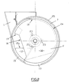
- la figure 1 est une vue de l'intérieur du carter du boîtier de distribution,
- la figure 2 est une vue correspondant à la figure 1, le disque étant en place,
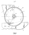
- la figure 3 est une vue correspondant à la figure 1 avec le disque et le rotor en place,
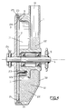
- la figure 4 est une vue en coupe suivant la ligne 4-4 de la figure 3,
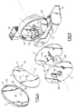
- la figure 5 est une vue en perspective éclatée du carter, du disque et du rotor,
- la figure 6 est une vue en perspective éclatée montrant le disque et le rotor vue de l'intérieur, et
- les figures 7 à 9 sont des vues explicatives du boîtier de distribution conforme à la présente invention, la figure 7 représentant le rotor vue de l'intérieur et les figures 8 et 9 étant des coupes partielles suivant les lignes 8-8 et 9-9 de la figure 3.
- FIG. 1 is a view of the interior of the casing of the distribution box,
- FIG. 2 is a view corresponding to FIG. 1, the disc being in place,
- FIG. 3 is a view corresponding to FIG. 1 with the disc and the rotor in place,
- FIG. 4 is a sectional view along line 4-4 of FIG. 3,
- FIG. 5 is an exploded perspective view of the casing, of the disc and of the rotor,
- FIG. 6 is an exploded perspective view showing the disc and the rotor seen from the inside, and
- Figures 7 to 9 are explanatory views of the distribution box according to the present invention, Figure 7 showing the rotor seen from the inside and Figures 8 and 9 being partial sections along lines 8-8 and 9-9 in Figure 3.
Comme on peut le voir sur les figures 1 à 6, le boîtier de distribution est essentiellement constitué de trois éléments, à savoir un carter 1 fixe, un disque 2 fixe et un rotor 3 tournant dans le sens des flèches indiquées en particulier sur les figures 3 et 5 à 7. Le carter 1 est de forme générale cylindrique, il comporte un fond vertical dans lequel est disposé à rotation un arbre d'entraînement 6. Ce carter 1 est alimenté en graines par une goulotte 10 reliée à une trémie d'alimentation non représentée. Par ailleurs, un soc 14 est fixé sous le carter 1 à l'avant du dispositif qui se déplace de la gauche vers la droite comme indiqué par une flèche sur la figure 3. Le carter 1 comporte une paroi cylindrique 25 et présente une ouverture 13 à la base du carter pour l'éjection des graines dans le soc 14; par ailleurs cette paroi cylindrique 25 supporte la goulotte 10 et présente au niveau de celle-ci, à sa partie supérieure, une ouverture permettant la descente des graines dans le carter.As can be seen in Figures 1 to 6, the distribution box consists essentially of three elements, namely a
Le carter 1 présente une face d'appui périphérique verticale 9 qui se raccorde à la paroi cylindrique 25 et est perpendiculaire à cette dernière. Cette face d'appui s'étend sensiblement de la partie supérieure du carter jusqu'à l'ouverture d'éjection 13. Dans sa partie basse, cette face d'appui constitue le fond 32 d'une chambre d'alimentation 11 s'étendant de ladite face d'appui 9 vers le fond du carter.The
Dans la partie montante de cette chambre d'alimentation 11, un secteur incliné 15 canalise les graines et facilite leur accès aux alvéoles du rotor.In the rising part of this
A sa partie supérieure, la face d'appui présente une rampe de sélection des graines 18.At its upper part, the bearing face has a
Le disque 2 est coaxial au carter 1; il présente une ouverture centrale dessinée au passage de l'arbre d'entraînement 6 et il est fixé sur le carter 1 au moyen de vis 23 s'engageant, par exemple, dans le support du palier de l'arbre 6.The
Ce disque 2 présente une échancrure 16 disposée au niveau de la partie montante du trajet des graines, sensiblement en regard du secteur incliné 15 du carter 1. Le bord de sortie, par rapport au sens de rotation du disque 3, de l'échancrure 16 comporte une rampe de sélection 17 dont la ligne de pente est sensiblement perpendiculaire au rayon du disque la traversant. Cette rampe s'étend du bord de sortie de l'échancrure 16 où elle constitue une arête 19 se trouvant sur la face 33 du disque faisant face au rotor 3. Cette rampe s'étend de cette arête 19 jusqu'à la face 34 opposée à la face 33 du disque 2.This
Le rotor de distribution 3 a la forme d'un disque comportant une couronne cylindrique 8; il comporte, suivant une forme de réalisation, un moyeu 36 par l'intermédiaire duquel il est solidarisé avec l'arbre d'entraînement 6, par exemple au moyen d'une clavette 26. Le rotor 3 est entraîné en rotation par l'arbre 6 qui est solidaire d'un pignon 5 entraîné par un système d'entraînement à chaîne non représenté à une vitesse proportionnelle à la vitesse d'avancement du semoir.The
Le rotor 3 comporte, à intervalles réguliers, des alvéoles 20 aménagées dans sa couronne périphérique et constituées par des encoches de cette dernière de manière que ces alvéoles 20 débouchent, d'une part, sur la partie extérieure de la couronne 8, et, d'autre part, sur la face intérieure de la couronne 8.The
Avantageusement, on prévoit en avant de chaque alvéole 20 par rapport au sens de rotation du rotor 3 un chanfrein de préférence oblique 21 aménagé dans la face interne de la couronne 8.Advantageously, a preferably
Le fonctionnement du distributeur qui vient d'être décrit est le suivant. On se réfèrera en particulier aux figures 3 et 4 qui représentent le boîtier de distribution lorsqu'il est assemblé et aux figures 7 à 9.The operation of the distributor which has just been described is as follows. Reference will be made in particular to FIGS. 3 and 4 which represent the distribution box when it is assembled and to FIGS. 7 to 9.
Les graines pénètrent dans la chambre d'alimentation 11 par la goulotte 10 et leur niveau se stabilise sensiblement au niveau 12a d'une fenêtre 12.The seeds enter the
Dans la partie basse du boîtier, les graines qui se trouvent au contact du rotor 3 ont tendance à être entraînées et à rouler sur la couronne 8. Les graines qui se trouvent au niveau du secteur incliné 15 du carter 1 et du chanfrein oblique 21 des alvéoles 20 se trouvent guidées et sont automatiquement dirigées vers les alvéoles 20 dont les dimensions sont déterminées de manière à ne pouvoir normalement recevoir qu'une seule graine.In the lower part of the housing, the seeds which are in contact with the
La force centrifuge engendrée par la vitesse de rotation élevée du rotor empêche les graines logées dans les alvéoles 20 de retomber et elles vont donc circuler dans le canal 9 jusqu'à l'orifice d'éjection 13 où, sous l'effet de la force centrifuge, les graines seront expulsées pour tomber par gravité dans le sillon creusé par le soc 14. La vitesse de rotation du rotor est suffisamment élevée pour que l'effet de la force centrifuge soit nettement plus important que l'effet d'entraînement du mouvement de rotation de la graine.The centrifugal force generated by the high speed of rotation of the rotor prevents the seeds housed in the
Lorsque les alvéoles atteignent le niveau de la rampe de sélection 17 du disque 2, (voir figure 8), l'arète 19 passe derrière chaque alvéole et la rampe 17 agit progressivement et chasse en douceur vers le côté ouvert de l'alvéole, c'est-à-dire vers l'intérieur du carter, une éventuelle deuxième graine 22a qui serait restée prisonnière dans l'épaisseur de la couronne 8. Ceci réalise donc une première sélection, c'est-à-dire une élimination des graines supplémentaire, dans laquelle les graines en excès sont évacuées horizontalement. En effet, le premier dispositif de sélection constitué par la rampe 17 est disposé sensiblement à la moitié de la course montante du trajet des graines.When the cells reach the level of the
Dans la partie haute du carter 1, les alvéoles atteignent ensuite la rampe 18 du carter 1 qui, à son tour, effectue une sélection progressive en éliminant vers le bas une éventuelle deuxième graine 22b (voir figure 9) qui serait restée prisionnère sur le côté de la première graine. On réalise ainsi une deuxième sélection verticale.In the upper part of the
Grâce à ce double dispositif de sélection, on obtient une sélection efficace, si bien qu'il reste une seule graine dans chaque alvéole; cette graine circule dans le canal 7 jusqu'à l'ouverture d'éjection 13.Thanks to this double selection device, efficient selection is obtained, so that only one seed remains in each cell; this seed circulates in the
On voit que l'invention permet de réaliser une sélection très efficace des graines, même dans le cas de graines de forme irrégulière. Ceci est obtenu grâce au disque 2 et au double dispositif de sélection horizontale 17 et verticale 18.It can be seen that the invention makes it possible to carry out a very efficient selection of seeds, even in the case of seeds of irregular shape. This is obtained by means of the
La description qui suit n'a été fournie qu'à titre d'exemple nullement limitatif et il est évident que l'on peut y apporter des modifications ou variantes sans pour autant sortir du cadre de la présente invention.The following description has been provided by way of non-limiting example only and it is obvious that modifications or variants can be made without departing from the scope of the present invention.
En particulier, le premier dispositif de sélection horizontale peut être réalisé sur le carter 1.In particular, the first horizontal selection device can be produced on the
Egalement, les rampes fixes progressives de sélection 17 et 18 pourraient être remplacées par des rampes souples ou par des brosses.Also, the fixed progressive selection ramps 17 and 18 could be replaced by flexible ramps or by brushes.
Claims (7)
Applications Claiming Priority (2)
| Application Number | Priority Date | Filing Date | Title |
|---|---|---|---|
| FR9309176A FR2708173B1 (en) | 1993-07-26 | 1993-07-26 | Distribution box for mechanical precision seed drill. |
| FR9309176 | 1993-07-26 |
Publications (2)
| Publication Number | Publication Date |
|---|---|
| EP0636306A1 true EP0636306A1 (en) | 1995-02-01 |
| EP0636306B1 EP0636306B1 (en) | 1997-09-24 |
Family
ID=9449632
Family Applications (1)
| Application Number | Title | Priority Date | Filing Date |
|---|---|---|---|
| EP19940401571 Revoked EP0636306B1 (en) | 1993-07-26 | 1994-07-07 | Distributer for a mechanical precision seed drill |
Country Status (3)
| Country | Link |
|---|---|
| EP (1) | EP0636306B1 (en) |
| DE (1) | DE69405830T2 (en) |
| FR (1) | FR2708173B1 (en) |
Cited By (10)
| Publication number | Priority date | Publication date | Assignee | Title |
|---|---|---|---|---|
| EP0941645A3 (en) * | 1998-03-07 | 2000-05-17 | Kverneland Accord GmbH & Co. KG | Seedingplate for a precision seeddrill |
| DE102012105048A1 (en) * | 2012-06-12 | 2013-12-12 | Horsch Maschinen Gmbh | Distribution unit for granular material, in particular sowing unit |
| DE102014216370A1 (en) | 2014-08-18 | 2016-02-18 | Horsch Maschinen Gmbh | Dosing disc of a distribution unit for granular material |
| DE102014111777A1 (en) | 2014-08-18 | 2016-02-18 | Horsch Maschinen Gmbh | Dosing unit for granular material |
| DE102015001896A1 (en) | 2015-02-26 | 2016-09-01 | Gerald Funck | Separation unit for granular material |
| EP3127414A1 (en) | 2015-08-03 | 2017-02-08 | Horsch Maschinen GmbH | Metering assembly for granular materials |
| DE102015112813A1 (en) | 2015-08-04 | 2017-02-09 | Horsch Maschinen Gmbh | Dosing unit and method for dosing granular material |
| US9591798B2 (en) | 2012-06-12 | 2017-03-14 | Horsch Maschinen Gmbh | Distributing unit for granular material, in particular a seeding unit |
| US10021825B2 (en) | 2014-08-18 | 2018-07-17 | Horsch Maschinen Gmbh | Metering disk of a distribution device for granular material |
| DE102018200128A1 (en) | 2018-01-05 | 2019-07-11 | Horsch Maschinen Gmbh | Dosing device for granular material |
Citations (3)
| Publication number | Priority date | Publication date | Assignee | Title |
|---|---|---|---|---|
| DE1283589B (en) * | 1966-03-04 | 1968-11-21 | Dr Wilhelm Knolle | Precision seeder |
| EP0026926A1 (en) * | 1979-10-04 | 1981-04-15 | Franz Kleine Maschinenfabrik GmbH & Co. | Seed-spacing sowing device |
| EP0380912A1 (en) * | 1989-01-31 | 1990-08-08 | ACCORD Landmaschinen Heinrich Weiste & Co. GmbH | Spacer drill |
-
1993
- 1993-07-26 FR FR9309176A patent/FR2708173B1/en not_active Expired - Fee Related
-
1994
- 1994-07-07 DE DE1994605830 patent/DE69405830T2/en not_active Revoked
- 1994-07-07 EP EP19940401571 patent/EP0636306B1/en not_active Revoked
Patent Citations (3)
| Publication number | Priority date | Publication date | Assignee | Title |
|---|---|---|---|---|
| DE1283589B (en) * | 1966-03-04 | 1968-11-21 | Dr Wilhelm Knolle | Precision seeder |
| EP0026926A1 (en) * | 1979-10-04 | 1981-04-15 | Franz Kleine Maschinenfabrik GmbH & Co. | Seed-spacing sowing device |
| EP0380912A1 (en) * | 1989-01-31 | 1990-08-08 | ACCORD Landmaschinen Heinrich Weiste & Co. GmbH | Spacer drill |
Cited By (22)
| Publication number | Priority date | Publication date | Assignee | Title |
|---|---|---|---|---|
| EP0941645A3 (en) * | 1998-03-07 | 2000-05-17 | Kverneland Accord GmbH & Co. KG | Seedingplate for a precision seeddrill |
| AU2013276633B2 (en) * | 2012-06-12 | 2017-02-23 | Horsch Maschinen Gmbh | Distribution unit for granular commodity, in particular a sowing unit |
| DE102012105048A1 (en) * | 2012-06-12 | 2013-12-12 | Horsch Maschinen Gmbh | Distribution unit for granular material, in particular sowing unit |
| WO2013186175A1 (en) | 2012-06-12 | 2013-12-19 | Horsch Maschinen Gmbh | Distribution unit for granular commodity, in particular a sowing unit |
| EP3412126A1 (en) | 2012-06-12 | 2018-12-12 | Horsch Maschinen GmbH | Distribution device for granular material, in particular seeding device |
| RU2638521C2 (en) * | 2012-06-12 | 2017-12-14 | Хорш Машинен Гмбх | Distribution unit for granular material, first of all sowing unit |
| EP3222131A1 (en) | 2012-06-12 | 2017-09-27 | Horsch Maschinen GmbH | Distribution device for granular material, in particular seeding device |
| US9596802B2 (en) | 2012-06-12 | 2017-03-21 | Horsch Maschinen Gmbh | Distribution unit for granular commodity, in particular a sowing unit |
| US9591798B2 (en) | 2012-06-12 | 2017-03-14 | Horsch Maschinen Gmbh | Distributing unit for granular material, in particular a seeding unit |
| EP2987395A1 (en) | 2014-08-18 | 2016-02-24 | Horsch Maschinen GmbH | Dosing disc of a distribution system for granluar material |
| EP2989877A1 (en) | 2014-08-18 | 2016-03-02 | Horsch Maschinen GmbH | Dising assembly for granular material |
| US9781876B2 (en) | 2014-08-18 | 2017-10-10 | Horsch Maschinen Gmbh | Metering unit for granular material |
| DE102014111777A1 (en) | 2014-08-18 | 2016-02-18 | Horsch Maschinen Gmbh | Dosing unit for granular material |
| US10021825B2 (en) | 2014-08-18 | 2018-07-17 | Horsch Maschinen Gmbh | Metering disk of a distribution device for granular material |
| DE102014216370A1 (en) | 2014-08-18 | 2016-02-18 | Horsch Maschinen Gmbh | Dosing disc of a distribution unit for granular material |
| WO2016135174A1 (en) | 2015-02-26 | 2016-09-01 | Gerald Funck | Separation unit for granular material |
| DE102015001896A1 (en) | 2015-02-26 | 2016-09-01 | Gerald Funck | Separation unit for granular material |
| DE102015112701A1 (en) | 2015-08-03 | 2017-02-09 | Horsch Maschinen Gmbh | Dosing unit for granular material |
| EP3127414A1 (en) | 2015-08-03 | 2017-02-08 | Horsch Maschinen GmbH | Metering assembly for granular materials |
| DE102015112813A1 (en) | 2015-08-04 | 2017-02-09 | Horsch Maschinen Gmbh | Dosing unit and method for dosing granular material |
| DE102015112813B4 (en) | 2015-08-04 | 2022-06-09 | Horsch Maschinen Gmbh | Dosing unit and method for dosing granular material |
| DE102018200128A1 (en) | 2018-01-05 | 2019-07-11 | Horsch Maschinen Gmbh | Dosing device for granular material |
Also Published As
| Publication number | Publication date |
|---|---|
| DE69405830D1 (en) | 1997-10-30 |
| DE69405830T2 (en) | 1998-01-15 |
| EP0636306B1 (en) | 1997-09-24 |
| FR2708173A1 (en) | 1995-02-03 |
| FR2708173B1 (en) | 1995-09-29 |
Similar Documents
| Publication | Publication Date | Title |
|---|---|---|
| EP0536768B1 (en) | Distributor for a precision drill | |
| EP2854499B1 (en) | Single grain seeder and seed singulation disc with open grooves | |
| WO2020001964A1 (en) | Assembly for dispensing granular products | |
| EP0636306B1 (en) | Distributer for a mechanical precision seed drill | |
| FR2713436A1 (en) | Seeder for single grain seeds | |
| EP0452214B1 (en) | Coffee mill and coffee machine equipped with such a mill | |
| FR2464017A1 (en) | PRECISION SIETING | |
| EP0046709A1 (en) | Distributing device for pneumatic precision drill | |
| EP0037337B1 (en) | Distributor for a precision seed drill | |
| EP0055948B1 (en) | Spraying equipment for liquid application, in particular for crop or soil treatments | |
| EP3238519A1 (en) | Device for controlling seed distribution for seeder, and corresponding seeder | |
| EP0230331B1 (en) | Device for peeling foodstuffs, in particular for shelling nuts | |
| FR2574243A1 (en) | Sowing machine for seeds, for example garlic seeds | |
| EP0050829B1 (en) | Planter unit for experimental plots | |
| FR2478941A1 (en) | DISPENSING DEVICE FOR A "MONOGRAINE" SEMOIR AND A PLANTER COMPRISING SUCH A DEVICE | |
| WO2000043304A1 (en) | Device for dispersing a divided solid material inside a receptacle | |
| EP1488674B1 (en) | Pneumatic seed distributor | |
| FR2643212A1 (en) | Distributor adjusting device for a seed spacing drill | |
| CH633488A5 (en) | APPARATUS FOR FEEDING DISK-LIKE OBJECTS. | |
| WO2001055728A1 (en) | Device for supplying a biological analysis apparatus with cuvettes and method for supplying such an apparatus | |
| BE512664A (en) | ||
| FR3134947A1 (en) | Device for accelerating at least one granular element, preferably a seed | |
| BE480800A (en) | ||
| FR2488480A1 (en) | Seed sowing drill with multiple distributors - has seed apertures which can be closed off to suit distributors | |
| FR2491721A1 (en) | Seed sower pick up drum - has several apertures in which individual seeds are held by suction and released by internal sealing roller |
Legal Events
| Date | Code | Title | Description |
|---|---|---|---|
| PUAI | Public reference made under article 153(3) epc to a published international application that has entered the european phase |
Free format text: ORIGINAL CODE: 0009012 |
|
| AK | Designated contracting states |
Kind code of ref document: A1 Designated state(s): BE DE GB IT |
|
| 17P | Request for examination filed |
Effective date: 19950725 |
|
| GRAG | Despatch of communication of intention to grant |
Free format text: ORIGINAL CODE: EPIDOS AGRA |
|
| GRAH | Despatch of communication of intention to grant a patent |
Free format text: ORIGINAL CODE: EPIDOS IGRA |
|
| 17Q | First examination report despatched |
Effective date: 19970219 |
|
| GRAH | Despatch of communication of intention to grant a patent |
Free format text: ORIGINAL CODE: EPIDOS IGRA |
|
| GRAA | (expected) grant |
Free format text: ORIGINAL CODE: 0009210 |
|
| AK | Designated contracting states |
Kind code of ref document: B1 Designated state(s): BE DE GB IT |
|
| ITF | It: translation for a ep patent filed |
Owner name: GUZZI E RAVIZZA S.R.L. |
|
| GBT | Gb: translation of ep patent filed (gb section 77(6)(a)/1977) |
Effective date: 19970929 |
|
| REF | Corresponds to: |
Ref document number: 69405830 Country of ref document: DE Date of ref document: 19971030 |
|
| PLBQ | Unpublished change to opponent data |
Free format text: ORIGINAL CODE: EPIDOS OPPO |
|
| PLBI | Opposition filed |
Free format text: ORIGINAL CODE: 0009260 |
|
| PLBF | Reply of patent proprietor to notice(s) of opposition |
Free format text: ORIGINAL CODE: EPIDOS OBSO |
|
| 26 | Opposition filed |
Opponent name: FRANZ KLEINE AGRARTECHNIK GMBH Effective date: 19980623 |
|
| PLBF | Reply of patent proprietor to notice(s) of opposition |
Free format text: ORIGINAL CODE: EPIDOS OBSO |
|
| PLBF | Reply of patent proprietor to notice(s) of opposition |
Free format text: ORIGINAL CODE: EPIDOS OBSO |
|
| PGFP | Annual fee paid to national office [announced via postgrant information from national office to epo] |
Ref country code: DE Payment date: 20000623 Year of fee payment: 7 |
|
| PGFP | Annual fee paid to national office [announced via postgrant information from national office to epo] |
Ref country code: GB Payment date: 20000630 Year of fee payment: 7 |
|
| PGFP | Annual fee paid to national office [announced via postgrant information from national office to epo] |
Ref country code: BE Payment date: 20000801 Year of fee payment: 7 |
|
| PLAB | Opposition data, opponent's data or that of the opponent's representative modified |
Free format text: ORIGINAL CODE: 0009299OPPO |
|
| R26 | Opposition filed (corrected) |
Opponent name: KVERNELAND SOEST GMBH Effective date: 19980623 |
|
| RDAH | Patent revoked |
Free format text: ORIGINAL CODE: EPIDOS REVO |
|
| RDAG | Patent revoked |
Free format text: ORIGINAL CODE: 0009271 |
|
| STAA | Information on the status of an ep patent application or granted ep patent |
Free format text: STATUS: PATENT REVOKED |
|
| 27W | Patent revoked |
Effective date: 20010312 |
|
| GBPR | Gb: patent revoked under art. 102 of the ep convention designating the uk as contracting state |
Free format text: 20010312 |
|
| PLAB | Opposition data, opponent's data or that of the opponent's representative modified |
Free format text: ORIGINAL CODE: 0009299OPPO |