EP0635682A1 - Chaudière-mixte à accumulation de chaleur - Google Patents
Chaudière-mixte à accumulation de chaleur Download PDFInfo
- Publication number
- EP0635682A1 EP0635682A1 EP94110862A EP94110862A EP0635682A1 EP 0635682 A1 EP0635682 A1 EP 0635682A1 EP 94110862 A EP94110862 A EP 94110862A EP 94110862 A EP94110862 A EP 94110862A EP 0635682 A1 EP0635682 A1 EP 0635682A1
- Authority
- EP
- European Patent Office
- Prior art keywords
- water
- heat exchanger
- boiler
- hot water
- duct
- Prior art date
- Legal status (The legal status is an assumption and is not a legal conclusion. Google has not performed a legal analysis and makes no representation as to the accuracy of the status listed.)
- Withdrawn
Links
Images
Classifications
-
- F—MECHANICAL ENGINEERING; LIGHTING; HEATING; WEAPONS; BLASTING
- F24—HEATING; RANGES; VENTILATING
- F24D—DOMESTIC- OR SPACE-HEATING SYSTEMS, e.g. CENTRAL HEATING SYSTEMS; DOMESTIC HOT-WATER SUPPLY SYSTEMS; ELEMENTS OR COMPONENTS THEREFOR
- F24D3/00—Hot-water central heating systems
- F24D3/08—Hot-water central heating systems in combination with systems for domestic hot-water supply
-
- F—MECHANICAL ENGINEERING; LIGHTING; HEATING; WEAPONS; BLASTING
- F24—HEATING; RANGES; VENTILATING
- F24D—DOMESTIC- OR SPACE-HEATING SYSTEMS, e.g. CENTRAL HEATING SYSTEMS; DOMESTIC HOT-WATER SUPPLY SYSTEMS; ELEMENTS OR COMPONENTS THEREFOR
- F24D2220/00—Components of central heating installations excluding heat sources
- F24D2220/08—Storage tanks
Definitions
- the present invention relates to a boiler of the so-called combined type comprising a first gas-water heat exchanger for producing primary hot water for space heating, a primary water piping circuit (5) for circulation of said water extending between a respective inlet and outlet openings of the boiler, a second water-water heat exchanger for producing hot sanitary water, as well as valve means for diverting selectively said primary hot water to said second water-water heat exchanger or to said outlet opening.
- boiler of the so-called combined type is meant a boiler capable of delivering either hot water for space heating or primary water, or hot water for sanitary use.
- a first shortcoming is correlated with the fact that, differently from boilers with instantaneous production of sanitary water, the accumulation boilers do not allow easy temperature control of the hot sanitary water, which can be achieved by varying the temperature of the water stored in the accumulation tank and, optionally, by mixing the latter with the cold water coming from the water mains.
- the flexibility of said control is also limited by the fact that the temperature of the water stored in the storage tank cannot exceed 50-55°C: beyond these values, in fact, there is formation of extensive calcareous deposits on the heating means provided in said tank, generally a coil in which circulates primary hot water.
- storage tanks must be manufactured in suitable materials, generally special porcelain-coated steel, of high cost; must be appropriately designed to resist the test pressure of the sanitary circuit of the boiler, in some countries equal to 22 bar, and must have flanged covers to allow opening for cleaning.
- the technical problem underlying the present invention is therefore that of conceiving and making available a boiler of the so-called combined type, which allows delivery of hot sanitary water at the desired temperature with large withdrawals thereof, while overcoming the shortcomings shown by the cited prior art.
- a boiler of the above mentioned type which is characterised in that it further comprises a heat accumulator, structurally independent of said second water-water exchanger, means being provided to allow heat exchange between said heat accumulator and said second water-water heat exchanger.
- the ability of the boiler to meet temporary high withdrawals of hot sanitary water is achieved by storing thermal energy in an appropriate heat accumulator and using the energy thus accumulated to supply to the water-water heat exchanger of the boiler and at times of greatest withdrawal, the heat surplus necessary to ensure delivery of sanitary water at the desired temperature.
- said thermal energy is stored by means of the primary hot water accumulated in a tank arranged in the primary water piping circuit of the boiler in parallel or in series with the gas-water heat exchanger and in fluid communication with the water-water heat exchanger designed for production of hot sanitary water.
- the same fluid which is normally employed as the heating fluid in boilers with instantaneous hot sanitary water production can be used advantageously as the vector of the accumulated energy.
- the present invention also makes available a module for conversion of a so-called combined type boiler with instantaneous sanitary water production into a heat accumulation boiler in accordance with the foregoing, which is characterised in that it comprises a supporting frame having means for connection to said boiler, a heat accumulator and means for installing the same in the primary water piping circuit in series or parallel with said first gas-water heat exchanger.
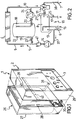
- numeral 1 indicates a so-called combined type boiler and in particular a wall boiler in accordance with a first embodiment of the present invention.
- the boiler 1 comprises a basically parallelepipedic vessel 2 equipped with a front control panel 3 comprising a known electronic control unit for control and regulation of the boiler.
- a gas-water heat exchanger 4 designed for producing primary hot water for space heating, in fluid communication through a primary piping circuit 5 with respective inlet opening 6 and outlet opening 7 respectively to and from the boiler and with a second water-water heat exchanger 8 designed for the producing hot sanitary water.
- the primary piping circuit 5 comprises a duct 9 for supplying primary water coming from a space heating circuit, not shown, to the gas-water heat exchanger 4 through a duct 37, as well as a return duct 10 from said gas-water heat exchanger 4.
- a non-return valve 41 and valve means 11 e.g. a 3-way valve, designed to set up a fluid connection between the gas-water heat exchanger 4 and the water-water heat exchanger 8 or the external heating circuit alternately.
- the primary piping circuit 5 comprises respective ducts 12 and 38.
- a duct 13 provides a fluid connection of the water-water heat exchanger 8 with the supply duct 9, while a pump 14 is provided in this same supply duct 9 to promote circulation of the water in the primary piping circuit 5.
- the water-water heat exchanger 8 is also in fluid communication with a secondary piping circuit 15 for taking cold sanitary water from the water mains and sending hot sanitary water to the users, which comprises an inlet duct 16 and an outlet duct 17 respectively to and from the water-water heat exchanger 8.
- Said ducts 9, 10 of the primary piping circuit and 16, 17 of the secondary piping circuit are equipped with fittings, known per se and therefore not shown, for connection with the remaining parts of the boiler or with external circuits in turn equipped with corresponding fittings, also not illustrated, designed to be fitted in a water-tight manner therewith.
- the boiler 1 comprises a heat accumulator 18, in this case a tank for accumulation of primary hot water, arranged in parallel with the gas-water heat exchanger 4.
- Said heat accumulator 18 is in fluid communication with the primary piping circuit 5 through respective ducts 19 and 20, respectively extending towards the supply duct 9 and the return duct 10 of the gas-water heat exchanger 4.
- a pump 21 of the so-called reversible variable speed type is mounted on the duct 20 and ensures circulation of the primary water from and to the tank 18, while thermostats 22, 23 and 24 provided in the tank 18 and the ducts 19 and 20 allow control of temperature and delivery of the water accumulated by the electronic control unit incorporated in the front control panel 3, as will be clarified hereinbelow.
- Reference number 25 indicates a thermostat for instantaneous detection of the temperature of the sanitary hot water produced in the boiler 1.
- the boiler 1 described above may be obtained from a pre-existing boiler of the combined type and with instantaneous sanitary hot water production, by connecting thereto a module indicated by 26 in figure 1 and incorporating the heat accumulator 18.
- the module 26 comprises a supporting frame 27 e.g. in parallelepipedic shape, provided with appropriate means for fastening to a wall and means for its connection to the frame of a pre-existing boiler with instantaneous sanitary water generation indicated by 29.
- the above mentioned means may comprise a plurality of hooks 28 onto which the boiler 29 can be hung by using the same means, such as e.g. a bar 42 extending transversely on the back thereof, which allow its installation on a wall.
- the ducts 19 and 20 have at their free ends appropriate means, e.g. fittings 30, 31, for insertion of the heat accumulator tank 18 in the primary piping circuit of the boiler 29 in parallel with the gas-water heat exchanger 4.
- the boiler 1 described hereinabove operates as follows.
- the temperature of the primary hot water accumulated in the heat accumulator tank 18 is kept at a constant value thanks to the intervention of the thermostat 22 which, when it detects a decrease in water temperature, controls the boiler burner in such a way as to deliver the maximum thermal power to the gas-water heat exchanger 4, interrupts circulation of the primary hot water to the room heating circuit by stopping the pump 14 and promotes water circulation towards the heat accumulator tank 18 by activating the pump 21.
- the non-return valve 41 ensures a correct fluid circulation from the gas-water heat exchanger 4 to the tank.
- the primary hot water flows therefore in a closed circuit, defined in the primary piping circuit 5, where it flows in sequence: through the gas-water heat exchanger 4, a portion of the return duct 10, the duct 20, the pump 21, the heat accumulator tank 18, the duct 19 and a portion of the supply duct 9.
- the thermostat 22 Upon reaching the desired temperature in the heat accumulator tank 18, the thermostat 22 stops operation of the pump 21 and, if necessary, restores circulation of the primary hot water to the exterior of the boiler 1.
- a flow sensor - not shown - provided on the inlet duct 16 activates in a known manner the burner and/or pump 14, if standing by, starts fluid circulation to the water-water heat exchanger 8 through the 3-way valve 11 and starts the pump 21 in the direction opposite the previous one, so as to withdraw a pre-set flowrate of primary hot water from the heat accumulator tank 18.
- the water withdrawn from the heat accumulator tank 18 is mixed in the last portion of the return duct 10 and in the duct 12, with the primary hot water coming from the gas-water heat exchanger 4 and sent together therewith to the water-water heat exchanger 8.
- the primary hot water coming from the water-water heat exchanger 8 where it has transferred its heat to the sanitary hot water therefore, branches in two parallel paths defined in the primary piping circuit 5: a first path including in sequence the supply duct 9, the gas-water heat exchanger 4 and the return duct 10 and a second path including in sequence the duct 19, the heat accumulator tank 18, the duct 20 and the pump 21.
- the amount of primary hot water withdrawal and hence the heat withdrawal from the heat accumulator tank 18, is determined by the thermostat 25 which instantaneously detects the temperature of the sanitary water delivered by the boiler 1 and adjusts consequently the flowrate taken from the pump 21.
- the withdrawal of primary hot water may advantageously continue - if necessary - up to a substantially complete use of the heat stored in the heat accumulator tank 18.
- the pump 21 is stopped when the temperature difference between the water entering the heat accumulator tank 18 and that which leaves the same, falls below a predetermined minimum value selected so as to ensure an adequate heat transfer to the cold sanitary water in the water-water heat exchanger 8.
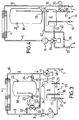
- FIGS 3 and 4 are diagramatically shown additional embodiments of the boiler 1 in accordance with the present invention.
- variable speed pump 21 which may be of the non-reversible type as well, is mounted on the duct 19 on which is provided downstream thereof a 3-way valve 32.
- the primary piping circuit 5 which comprises in sequence: the gas-water heat exchanger 4, a portion of return duct 10, the duct 20, the heat accumulator tank 18, the pump 21, the 3-way valve 32, the duct 33 and a portion of the supply duct 9.
- the flow sensor provided on the inlet duct 16 in addition to activating the burner and/or the pump 14, if on stand-by, starts the variable speed pump 21 and switches the water flow drawn from the heat accumulator tank 18 to the duct 34 through the 3-way valve 32.
- a first operating condition in which the flowrate of the variable speed pump 21 is less than that of the pump 14, the water taken from the tank 18 is mixed - in the last portion of the duct 10 and in the duct 12 - with the primary hot water coming from the gas-water heat exchanger 4 and is sent together with the latter to the water-water heat exchanger 8.
- the primary water circulates in a single path including in sequence the entire duct 9, the gas-water heat exchanger 4 and a first portion of the duct 10, the duct 20, the tank 18, the pump 21, the 3-way valve 32, the duct 34 and then a last portion of the duct 10.
- the gas-water heat exchanger 4 and the tank 18 are therefore connected in series with one another: the primary water heated by the gas-water heat exchanger 4 is sent entirely into the tank 18 where it replaces the accumulated hot water delivered to the water-water heat exchanger 8 by the pump 21.
- the amount of primary hot water drawn and hence the heat withdrawal from the tank 18, is determined by the thermostat 25 which instantaneously detects the temperature of the sanitary water delivered by the boiler 1 and, based thereon, adjusts the flowrate withdrawn by the pump 21.
- the withdrawal of the water accumulated in the tank 18 is interrupted when the temperature difference between the water entering and leaving the tank 18, measured in this case by the thermostats 24 and 23 respectively, falls below a pre-set minimum value.
- the duct 34 of the boiler illustrated in figure 3 can be connected directly to the inlet duct 12 leading to the water-water heat exchanger 8, bypassing the 3-way valve 11 as shown e.g. with dot and dash lines in figure 3.
- the boiler of the present invention allows heating of the sanitary water for small withdrawals by using exclusively the heat accumulated in the tank 18 and without interrupting the primary hot water delivery to the heating circuit outside the boiler or without starting the boiler burner.
- the module 26 obviously comprises the additional elements provided therein, i.e. the 3-way valve 32 and the ducts 33 and 34 with respective fittings.
- the primary hot water accumulation tank is arranged in the primary piping circuit 5 in series to the gas-water heat exchanger 4.
- a 3-way valve 36 and a cut-off valve 35 are mounted on the ducts 37 and 38 respectively provided for fluid connection with the heating circuit outside the boiler 1.
- the outlet duct 13 for supplying hot water for space heating from the water-water heat exchanger 8 and the duct 9 for connection to the gas-water heat exchanger 4, are also connected to the 3-way valve 36.
- the tank 18 is respectively connected to the return duct 10 and to the duct 37 through ducts 20 and 40.
- a one-way valve 39 to allow a water flow exclusively towards the duct 37.
- the temperature of the primary hot water accumulated in the tank 18 is held steady thanks to the intervention of the thermostat 22 which, upon each lowering of water temperature, controls the boiler burner so as to deliver the maximum thermal power to the gas-water heat exchanger 4, interrupts fluid circulation to the heating circuit through the cut-off valve 35 and switches the 3-way valve 36 so as to allow fluid communication between the ducts 37 and 9.
- the primary hot water therefore, flows in a first path, defined in the primary circuit 5, including in sequence: the gas-water heat exchanger 4, a portion of the duct 10, the duct 20, the tank 18, the duct 40, the one-way valve 39, the duct 37, the 3-way valve 36, the pump 14 and the duct 9 up to the gas-water heat exchanger 4.
- the flow sensor provided in the duct 16 activates in a known manner the burner and/or the pump 14, if on stand-by, and switches the 3-way valve 36 so as to allow fluid communication between the ducts 13 and 9 and interrupting fluid circulation to the heating circuit.
- the primary hot water transfers its heat to the hot sanitary water in the water-water heat exchanger 8 circulating in a second path, defined in the primary circuit 5 and including in sequence: the gas-water heat exchanger 4, the duct 10, the duct 20, the tank 18, the duct 19, the water-water heat exchanger 8, the duct 13, the 3-way valve 36, the pump 14 and the duct 9.
- the primary water heated by the gas-water heat exchanger 4 is sent into the tank 18 where it replaces the accumulated hot water delivered to the water-water heat exchanger 8 by the pump 14.
- control of the heat transfer by the accumulated hot water to the sanitary water is achieved by the thermostat 25 which adjusts the flowrate of the pump 14 and the thermal power delivered by the burner to the gas-water heat exchanger 4.
- the boiler 1 may send again, if necessary, hot water to the space heating circuit after activation of the pump 14 and switching of the 3-way valve 36 so as to allow fluid communication between the ducts 37 and 9.
- the boiler 1 in accordance with the present invention allows, differently from conventional accumulation boilers, an extremely flexible temperature control of the delivered sanitary water, by mere control of the flowrate of hot water withdrawn from the accumulation tank.
- the boiler of the present invention allows therefore an optimal use of the accumulated heat, which can be gradually delivered to meet in an extremely flexible and lasting manner the most varied hot sanitary water withdrawal requirements.
- the temperature reachable in the tank 18 (up to 85-90°C) and hence the quantity of thermal energy stored, are much greater than the maximums allowed by conventional accumulation boilers, where said temperature is limited by the known problems of calcareous deposits build-up.
- the boiler of the present invention can consequently meet high withdrawals of hot sanitary water for a longer time, i.e. occupy less space for a given performance.
- the accumulation tank in fact, is substantially maintenance-free and is entirely free of all those structural, hygienic and sanitary requirements which standards impose on accumulation tanks for hot sanitary water of conventional boilers.
- Said tank may therefore be manufactured in carbon steel and in the most varied shapes so as to make the best possible use of the space available.
- the present invention also allows to achieve the advantages mentioned above with minimal use of labour and at relatively low cost.
- the boiler of the present invention comprises elements of extremely simple construction which can be mass produced at low unit cost.
Landscapes
- Engineering & Computer Science (AREA)
- Water Supply & Treatment (AREA)
- Physics & Mathematics (AREA)
- Thermal Sciences (AREA)
- Chemical & Material Sciences (AREA)
- Combustion & Propulsion (AREA)
- Mechanical Engineering (AREA)
- General Engineering & Computer Science (AREA)
- Heat-Pump Type And Storage Water Heaters (AREA)
- Steam Or Hot-Water Central Heating Systems (AREA)
Applications Claiming Priority (2)
| Application Number | Priority Date | Filing Date | Title |
|---|---|---|---|
| ITMI931603A IT1272474B (it) | 1993-07-20 | 1993-07-20 | Caldaia del tipo cosiddetto combinato ad accumulo di calore. |
| ITMI931603 | 1993-07-20 |
Publications (1)
| Publication Number | Publication Date |
|---|---|
| EP0635682A1 true EP0635682A1 (fr) | 1995-01-25 |
Family
ID=11366641
Family Applications (1)
| Application Number | Title | Priority Date | Filing Date |
|---|---|---|---|
| EP94110862A Withdrawn EP0635682A1 (fr) | 1993-07-20 | 1994-07-13 | Chaudière-mixte à accumulation de chaleur |
Country Status (2)
| Country | Link |
|---|---|
| EP (1) | EP0635682A1 (fr) |
| IT (1) | IT1272474B (fr) |
Cited By (16)
| Publication number | Priority date | Publication date | Assignee | Title |
|---|---|---|---|---|
| GB2293438A (en) * | 1994-09-20 | 1996-03-27 | Gledhill Water Storage | The control of water heating apparatus to prevent scalding |
| AT402662B (de) * | 1995-04-03 | 1997-07-25 | Vaillant Gmbh | Heizanlage mit einem brennerbeheizten heizanlage mit einem brennerbeheizten primärwärmetauscher primärwärmetauscher |
| WO1997036138A1 (fr) * | 1996-03-27 | 1997-10-02 | Alf Ottosson | Technique et appareil de commande de la temperature de l'eau d'un robinet d'eau chaude |
| EP0916901A1 (fr) * | 1997-11-11 | 1999-05-19 | IABER S.p.A. | Appareil pour réduire le tartrage pour chauffe-eau à gaz |
| EP0843133A3 (fr) * | 1996-11-15 | 1999-10-27 | Richard Vetter | Chaudière à eau chaude |
| EP1026449A1 (fr) * | 1999-02-03 | 2000-08-09 | IABER S.p.A. | Chaudière avec écoulement maximal |
| FR2817610A1 (fr) * | 2000-12-05 | 2002-06-07 | Dietrich Thermique | Circuit de preparation d'eau chaude sanitaire pour un chauffe-eau ou une chaudiere |
| WO2003014627A1 (fr) * | 2001-08-10 | 2003-02-20 | Queen's University At Kingston | Systeme d'energie thermique a rinçage par ecoulement inverse passif |
| CN1111272C (zh) * | 1999-08-08 | 2003-06-11 | 许富昌 | 集中供热系统使用热水表计量采暖用户用热量的方法 |
| WO2003098118A3 (fr) * | 2002-05-17 | 2004-04-29 | Vebteck Res Inc | Systeme combine de chauffage et de distribution d'eau chaude |
| EP1528328A1 (fr) * | 2003-11-03 | 2005-05-04 | Grundfos A/S | Module pour installation de chauffage compacte |
| EP1577615A1 (fr) * | 2004-03-17 | 2005-09-21 | Martin Sandler Systemtechnik E.K. | Procédé et dispositif pour la production de l'eau sanitaire avec un échangeur de chaleur |
| EP1617149A1 (fr) * | 2004-07-14 | 2006-01-18 | BERTOLI, Marco | Chauffe-eau instantané |
| WO2013165106A1 (fr) * | 2012-05-03 | 2013-11-07 | 주식회사 경동나비엔 | Chaudière avec une efficacité de chauffage d'intérieur supérieure et permettant l'utilisation simultanée du chauffage d'intérieur et de l'eau chaude |
| WO2014051268A1 (fr) * | 2012-09-28 | 2014-04-03 | 주식회사 경동나비엔 | Structure pour réguler la température d'une alimentation en eau chaude depuis un système de récupération de chaleur perdue utilisant une vanne à trois voies ou une vanne de mélange, et structure pour réguler une température d'alimentation en eau chaude depuis un système de récupération de chaleur perdue utilisant un échangeur de chaleur dans un réservoir d'eau chaude |
| EP1801507A3 (fr) * | 2005-08-03 | 2015-09-02 | Eco heating systems B.V. | Dispositif de distribution de liquide chaud et appareil de chauffage pour ce dispositif. |
Citations (3)
| Publication number | Priority date | Publication date | Assignee | Title |
|---|---|---|---|---|
| CH180906A (de) * | 1935-01-09 | 1935-11-30 | Ctc Ab | Warmwasserversorgungsanlage mit mittelbarer Erwärmung des Abzapfwassers in einem Rohrsystem. |
| DE4236967A1 (en) * | 1991-11-04 | 1993-05-06 | Joh. Vaillant Gmbh U. Co, 5630 Remscheid, De | Heating system with circulating pump - has hot-water storage tank in series with primary branch of heat-exchanger |
| GB2262593A (en) * | 1991-12-17 | 1993-06-23 | Inter Albion Ltd | An apparatus for and method of providing hot sanitary water |
-
1993
- 1993-07-20 IT ITMI931603A patent/IT1272474B/it active IP Right Grant
-
1994
- 1994-07-13 EP EP94110862A patent/EP0635682A1/fr not_active Withdrawn
Patent Citations (3)
| Publication number | Priority date | Publication date | Assignee | Title |
|---|---|---|---|---|
| CH180906A (de) * | 1935-01-09 | 1935-11-30 | Ctc Ab | Warmwasserversorgungsanlage mit mittelbarer Erwärmung des Abzapfwassers in einem Rohrsystem. |
| DE4236967A1 (en) * | 1991-11-04 | 1993-05-06 | Joh. Vaillant Gmbh U. Co, 5630 Remscheid, De | Heating system with circulating pump - has hot-water storage tank in series with primary branch of heat-exchanger |
| GB2262593A (en) * | 1991-12-17 | 1993-06-23 | Inter Albion Ltd | An apparatus for and method of providing hot sanitary water |
Cited By (25)
| Publication number | Priority date | Publication date | Assignee | Title |
|---|---|---|---|---|
| GB2293438A (en) * | 1994-09-20 | 1996-03-27 | Gledhill Water Storage | The control of water heating apparatus to prevent scalding |
| AT402662B (de) * | 1995-04-03 | 1997-07-25 | Vaillant Gmbh | Heizanlage mit einem brennerbeheizten heizanlage mit einem brennerbeheizten primärwärmetauscher primärwärmetauscher |
| WO1997036138A1 (fr) * | 1996-03-27 | 1997-10-02 | Alf Ottosson | Technique et appareil de commande de la temperature de l'eau d'un robinet d'eau chaude |
| AU703631B2 (en) * | 1996-03-27 | 1999-03-25 | Alf Ottosson | Method and device for temperature control of hot tap-water |
| EP0843133A3 (fr) * | 1996-11-15 | 1999-10-27 | Richard Vetter | Chaudière à eau chaude |
| EP0916901A1 (fr) * | 1997-11-11 | 1999-05-19 | IABER S.p.A. | Appareil pour réduire le tartrage pour chauffe-eau à gaz |
| EP1026449A1 (fr) * | 1999-02-03 | 2000-08-09 | IABER S.p.A. | Chaudière avec écoulement maximal |
| CN1111272C (zh) * | 1999-08-08 | 2003-06-11 | 许富昌 | 集中供热系统使用热水表计量采暖用户用热量的方法 |
| FR2817610A1 (fr) * | 2000-12-05 | 2002-06-07 | Dietrich Thermique | Circuit de preparation d'eau chaude sanitaire pour un chauffe-eau ou une chaudiere |
| WO2003014627A1 (fr) * | 2001-08-10 | 2003-02-20 | Queen's University At Kingston | Systeme d'energie thermique a rinçage par ecoulement inverse passif |
| US6827091B2 (en) | 2001-08-10 | 2004-12-07 | Queen's University At Kingston | Passive back-flushing thermal energy system |
| US7171972B2 (en) | 2001-08-10 | 2007-02-06 | Queen's University At Kingston | Passive back-flushing thermal energy system |
| US7823628B2 (en) | 2001-08-10 | 2010-11-02 | Queen's University At Kingston | Passive back-flushing thermal energy system |
| WO2003098118A3 (fr) * | 2002-05-17 | 2004-04-29 | Vebteck Res Inc | Systeme combine de chauffage et de distribution d'eau chaude |
| EP1528328A1 (fr) * | 2003-11-03 | 2005-05-04 | Grundfos A/S | Module pour installation de chauffage compacte |
| EP1909041A1 (fr) * | 2003-11-03 | 2008-04-09 | Grundfos a/s | Composant pour installation de chauffage compacte |
| EP1577615A1 (fr) * | 2004-03-17 | 2005-09-21 | Martin Sandler Systemtechnik E.K. | Procédé et dispositif pour la production de l'eau sanitaire avec un échangeur de chaleur |
| EP1617149A1 (fr) * | 2004-07-14 | 2006-01-18 | BERTOLI, Marco | Chauffe-eau instantané |
| EP1801507A3 (fr) * | 2005-08-03 | 2015-09-02 | Eco heating systems B.V. | Dispositif de distribution de liquide chaud et appareil de chauffage pour ce dispositif. |
| WO2013165106A1 (fr) * | 2012-05-03 | 2013-11-07 | 주식회사 경동나비엔 | Chaudière avec une efficacité de chauffage d'intérieur supérieure et permettant l'utilisation simultanée du chauffage d'intérieur et de l'eau chaude |
| CN104272030A (zh) * | 2012-05-03 | 2015-01-07 | 庆东纳碧安株式会社 | 提高供暖效率的可同时使用供暖及热水的锅炉 |
| CN104272030B (zh) * | 2012-05-03 | 2017-05-10 | 庆东纳碧安株式会社 | 提高供暖效率的可同时使用供暖及热水的锅炉 |
| US9869490B2 (en) | 2012-05-03 | 2018-01-16 | Kyungdong Navien Co., Ltd. | Boiler having increased indoor heating efficiency and enabling simultaneous use of indoor heating and hot water |
| WO2014051268A1 (fr) * | 2012-09-28 | 2014-04-03 | 주식회사 경동나비엔 | Structure pour réguler la température d'une alimentation en eau chaude depuis un système de récupération de chaleur perdue utilisant une vanne à trois voies ou une vanne de mélange, et structure pour réguler une température d'alimentation en eau chaude depuis un système de récupération de chaleur perdue utilisant un échangeur de chaleur dans un réservoir d'eau chaude |
| AU2013320791B2 (en) * | 2012-09-28 | 2016-01-07 | Kyungdong Navien Co., Ltd. | Structure for controlling temperature of hot- water supply from waste heat recovery system using three-way valve or mixing valve, and structure for controlling temperature of hot- water supply from waste heat recovery system using heat exchanger in hot- water tank |
Also Published As
| Publication number | Publication date |
|---|---|
| ITMI931603A0 (it) | 1993-07-20 |
| IT1272474B (it) | 1997-06-23 |
| ITMI931603A1 (it) | 1995-01-20 |
Similar Documents
| Publication | Publication Date | Title |
|---|---|---|
| EP0635682A1 (fr) | Chaudière-mixte à accumulation de chaleur | |
| EP1957876B1 (fr) | Système de chauffage | |
| CA2080946C (fr) | Systeme de stockage d'eau chaude | |
| US11002492B2 (en) | Energy storage system | |
| EP0422738B1 (fr) | Appareil pour la distribution de quantités d'eau de température variable | |
| EP0820543B1 (fr) | Agencement pour fer a repasser | |
| EP0692682B1 (fr) | Dispositif de chaudière, en particulier chaudière mixte avec délivrance instantanée d'eau chaude sanitaire | |
| EP0740113A1 (fr) | Chaudière mixte avec performance améliorée | |
| KR19990076959A (ko) | 가열 장치 및 그 작동 방법 | |
| EP1983267A2 (fr) | Système de chauffage à énergie solaire et procédé de chauffage l'utilisant | |
| EP0355881B1 (fr) | Appareil pour chauffer de l'eau sanitaire | |
| JP2004020013A (ja) | 貯湯式給湯装置 | |
| AU635027B2 (en) | Improvements to hot water tanks and installations equipped with such tanks | |
| EP1039236A2 (fr) | Chaudière mixte à accumulation | |
| EP0940636B1 (fr) | Chaudière de chauffage et de préparation d'eau chaude sanitaire | |
| KR200370859Y1 (ko) | 난방 및 급탕 온수 공급 시스템 | |
| CN108800267A (zh) | 电热相变蓄能供热机组及其变工况能量调节方法 | |
| CN215765779U (zh) | 一种家用全预混冷凝壁挂炉与储热水箱一体机 | |
| CN219390100U (zh) | 加热装置和热水器 | |
| CZ20022816A3 (cs) | Způsob ohřevu vody a ohřívač k jeho provádění | |
| KR100603962B1 (ko) | 난방 및 급탕 온수 공급 시스템 | |
| JPS60155855A (ja) | 温水加熱装置 | |
| EP0943877A2 (fr) | Chauffe-eau sanitaire | |
| EP0509611A1 (fr) | Chaudière mixte comprenant un échangeur de chaleur avec des pompes intégrés | |
| AU2021204164A1 (en) | Water heating system |
Legal Events
| Date | Code | Title | Description |
|---|---|---|---|
| PUAI | Public reference made under article 153(3) epc to a published international application that has entered the european phase |
Free format text: ORIGINAL CODE: 0009012 |
|
| AK | Designated contracting states |
Kind code of ref document: A1 Designated state(s): DE ES FR GB IT NL |
|
| RAP1 | Party data changed (applicant data changed or rights of an application transferred) |
Owner name: INTEGRA S.R.L. |
|
| 17P | Request for examination filed |
Effective date: 19950713 |
|
| 17Q | First examination report despatched |
Effective date: 19970606 |
|
| STAA | Information on the status of an ep patent application or granted ep patent |
Free format text: STATUS: THE APPLICATION IS DEEMED TO BE WITHDRAWN |
|
| 18D | Application deemed to be withdrawn |
Effective date: 19971017 |