EP0635682A1 - Boiler of the so-called combined heat accumulation type - Google Patents
Boiler of the so-called combined heat accumulation type Download PDFInfo
- Publication number
- EP0635682A1 EP0635682A1 EP94110862A EP94110862A EP0635682A1 EP 0635682 A1 EP0635682 A1 EP 0635682A1 EP 94110862 A EP94110862 A EP 94110862A EP 94110862 A EP94110862 A EP 94110862A EP 0635682 A1 EP0635682 A1 EP 0635682A1
- Authority
- EP
- European Patent Office
- Prior art keywords
- water
- heat exchanger
- boiler
- hot water
- duct
- Prior art date
- Legal status (The legal status is an assumption and is not a legal conclusion. Google has not performed a legal analysis and makes no representation as to the accuracy of the status listed.)
- Withdrawn
Links
Images
Classifications
-
- F—MECHANICAL ENGINEERING; LIGHTING; HEATING; WEAPONS; BLASTING
- F24—HEATING; RANGES; VENTILATING
- F24D—DOMESTIC- OR SPACE-HEATING SYSTEMS, e.g. CENTRAL HEATING SYSTEMS; DOMESTIC HOT-WATER SUPPLY SYSTEMS; ELEMENTS OR COMPONENTS THEREFOR
- F24D3/00—Hot-water central heating systems
- F24D3/08—Hot-water central heating systems in combination with systems for domestic hot-water supply
-
- F—MECHANICAL ENGINEERING; LIGHTING; HEATING; WEAPONS; BLASTING
- F24—HEATING; RANGES; VENTILATING
- F24D—DOMESTIC- OR SPACE-HEATING SYSTEMS, e.g. CENTRAL HEATING SYSTEMS; DOMESTIC HOT-WATER SUPPLY SYSTEMS; ELEMENTS OR COMPONENTS THEREFOR
- F24D2220/00—Components of central heating installations excluding heat sources
- F24D2220/08—Storage tanks
Definitions
- the present invention relates to a boiler of the so-called combined type comprising a first gas-water heat exchanger for producing primary hot water for space heating, a primary water piping circuit (5) for circulation of said water extending between a respective inlet and outlet openings of the boiler, a second water-water heat exchanger for producing hot sanitary water, as well as valve means for diverting selectively said primary hot water to said second water-water heat exchanger or to said outlet opening.
- boiler of the so-called combined type is meant a boiler capable of delivering either hot water for space heating or primary water, or hot water for sanitary use.
- a first shortcoming is correlated with the fact that, differently from boilers with instantaneous production of sanitary water, the accumulation boilers do not allow easy temperature control of the hot sanitary water, which can be achieved by varying the temperature of the water stored in the accumulation tank and, optionally, by mixing the latter with the cold water coming from the water mains.
- the flexibility of said control is also limited by the fact that the temperature of the water stored in the storage tank cannot exceed 50-55°C: beyond these values, in fact, there is formation of extensive calcareous deposits on the heating means provided in said tank, generally a coil in which circulates primary hot water.
- storage tanks must be manufactured in suitable materials, generally special porcelain-coated steel, of high cost; must be appropriately designed to resist the test pressure of the sanitary circuit of the boiler, in some countries equal to 22 bar, and must have flanged covers to allow opening for cleaning.
- the technical problem underlying the present invention is therefore that of conceiving and making available a boiler of the so-called combined type, which allows delivery of hot sanitary water at the desired temperature with large withdrawals thereof, while overcoming the shortcomings shown by the cited prior art.
- a boiler of the above mentioned type which is characterised in that it further comprises a heat accumulator, structurally independent of said second water-water exchanger, means being provided to allow heat exchange between said heat accumulator and said second water-water heat exchanger.
- the ability of the boiler to meet temporary high withdrawals of hot sanitary water is achieved by storing thermal energy in an appropriate heat accumulator and using the energy thus accumulated to supply to the water-water heat exchanger of the boiler and at times of greatest withdrawal, the heat surplus necessary to ensure delivery of sanitary water at the desired temperature.
- said thermal energy is stored by means of the primary hot water accumulated in a tank arranged in the primary water piping circuit of the boiler in parallel or in series with the gas-water heat exchanger and in fluid communication with the water-water heat exchanger designed for production of hot sanitary water.
- the same fluid which is normally employed as the heating fluid in boilers with instantaneous hot sanitary water production can be used advantageously as the vector of the accumulated energy.
- the present invention also makes available a module for conversion of a so-called combined type boiler with instantaneous sanitary water production into a heat accumulation boiler in accordance with the foregoing, which is characterised in that it comprises a supporting frame having means for connection to said boiler, a heat accumulator and means for installing the same in the primary water piping circuit in series or parallel with said first gas-water heat exchanger.
- numeral 1 indicates a so-called combined type boiler and in particular a wall boiler in accordance with a first embodiment of the present invention.
- the boiler 1 comprises a basically parallelepipedic vessel 2 equipped with a front control panel 3 comprising a known electronic control unit for control and regulation of the boiler.
- a gas-water heat exchanger 4 designed for producing primary hot water for space heating, in fluid communication through a primary piping circuit 5 with respective inlet opening 6 and outlet opening 7 respectively to and from the boiler and with a second water-water heat exchanger 8 designed for the producing hot sanitary water.
- the primary piping circuit 5 comprises a duct 9 for supplying primary water coming from a space heating circuit, not shown, to the gas-water heat exchanger 4 through a duct 37, as well as a return duct 10 from said gas-water heat exchanger 4.
- a non-return valve 41 and valve means 11 e.g. a 3-way valve, designed to set up a fluid connection between the gas-water heat exchanger 4 and the water-water heat exchanger 8 or the external heating circuit alternately.
- the primary piping circuit 5 comprises respective ducts 12 and 38.
- a duct 13 provides a fluid connection of the water-water heat exchanger 8 with the supply duct 9, while a pump 14 is provided in this same supply duct 9 to promote circulation of the water in the primary piping circuit 5.
- the water-water heat exchanger 8 is also in fluid communication with a secondary piping circuit 15 for taking cold sanitary water from the water mains and sending hot sanitary water to the users, which comprises an inlet duct 16 and an outlet duct 17 respectively to and from the water-water heat exchanger 8.
- Said ducts 9, 10 of the primary piping circuit and 16, 17 of the secondary piping circuit are equipped with fittings, known per se and therefore not shown, for connection with the remaining parts of the boiler or with external circuits in turn equipped with corresponding fittings, also not illustrated, designed to be fitted in a water-tight manner therewith.
- the boiler 1 comprises a heat accumulator 18, in this case a tank for accumulation of primary hot water, arranged in parallel with the gas-water heat exchanger 4.
- Said heat accumulator 18 is in fluid communication with the primary piping circuit 5 through respective ducts 19 and 20, respectively extending towards the supply duct 9 and the return duct 10 of the gas-water heat exchanger 4.
- a pump 21 of the so-called reversible variable speed type is mounted on the duct 20 and ensures circulation of the primary water from and to the tank 18, while thermostats 22, 23 and 24 provided in the tank 18 and the ducts 19 and 20 allow control of temperature and delivery of the water accumulated by the electronic control unit incorporated in the front control panel 3, as will be clarified hereinbelow.
- Reference number 25 indicates a thermostat for instantaneous detection of the temperature of the sanitary hot water produced in the boiler 1.
- the boiler 1 described above may be obtained from a pre-existing boiler of the combined type and with instantaneous sanitary hot water production, by connecting thereto a module indicated by 26 in figure 1 and incorporating the heat accumulator 18.
- the module 26 comprises a supporting frame 27 e.g. in parallelepipedic shape, provided with appropriate means for fastening to a wall and means for its connection to the frame of a pre-existing boiler with instantaneous sanitary water generation indicated by 29.
- the above mentioned means may comprise a plurality of hooks 28 onto which the boiler 29 can be hung by using the same means, such as e.g. a bar 42 extending transversely on the back thereof, which allow its installation on a wall.
- the ducts 19 and 20 have at their free ends appropriate means, e.g. fittings 30, 31, for insertion of the heat accumulator tank 18 in the primary piping circuit of the boiler 29 in parallel with the gas-water heat exchanger 4.
- the boiler 1 described hereinabove operates as follows.
- the temperature of the primary hot water accumulated in the heat accumulator tank 18 is kept at a constant value thanks to the intervention of the thermostat 22 which, when it detects a decrease in water temperature, controls the boiler burner in such a way as to deliver the maximum thermal power to the gas-water heat exchanger 4, interrupts circulation of the primary hot water to the room heating circuit by stopping the pump 14 and promotes water circulation towards the heat accumulator tank 18 by activating the pump 21.
- the non-return valve 41 ensures a correct fluid circulation from the gas-water heat exchanger 4 to the tank.
- the primary hot water flows therefore in a closed circuit, defined in the primary piping circuit 5, where it flows in sequence: through the gas-water heat exchanger 4, a portion of the return duct 10, the duct 20, the pump 21, the heat accumulator tank 18, the duct 19 and a portion of the supply duct 9.
- the thermostat 22 Upon reaching the desired temperature in the heat accumulator tank 18, the thermostat 22 stops operation of the pump 21 and, if necessary, restores circulation of the primary hot water to the exterior of the boiler 1.
- a flow sensor - not shown - provided on the inlet duct 16 activates in a known manner the burner and/or pump 14, if standing by, starts fluid circulation to the water-water heat exchanger 8 through the 3-way valve 11 and starts the pump 21 in the direction opposite the previous one, so as to withdraw a pre-set flowrate of primary hot water from the heat accumulator tank 18.
- the water withdrawn from the heat accumulator tank 18 is mixed in the last portion of the return duct 10 and in the duct 12, with the primary hot water coming from the gas-water heat exchanger 4 and sent together therewith to the water-water heat exchanger 8.
- the primary hot water coming from the water-water heat exchanger 8 where it has transferred its heat to the sanitary hot water therefore, branches in two parallel paths defined in the primary piping circuit 5: a first path including in sequence the supply duct 9, the gas-water heat exchanger 4 and the return duct 10 and a second path including in sequence the duct 19, the heat accumulator tank 18, the duct 20 and the pump 21.
- the amount of primary hot water withdrawal and hence the heat withdrawal from the heat accumulator tank 18, is determined by the thermostat 25 which instantaneously detects the temperature of the sanitary water delivered by the boiler 1 and adjusts consequently the flowrate taken from the pump 21.
- the withdrawal of primary hot water may advantageously continue - if necessary - up to a substantially complete use of the heat stored in the heat accumulator tank 18.
- the pump 21 is stopped when the temperature difference between the water entering the heat accumulator tank 18 and that which leaves the same, falls below a predetermined minimum value selected so as to ensure an adequate heat transfer to the cold sanitary water in the water-water heat exchanger 8.
- FIGS 3 and 4 are diagramatically shown additional embodiments of the boiler 1 in accordance with the present invention.
- variable speed pump 21 which may be of the non-reversible type as well, is mounted on the duct 19 on which is provided downstream thereof a 3-way valve 32.
- the primary piping circuit 5 which comprises in sequence: the gas-water heat exchanger 4, a portion of return duct 10, the duct 20, the heat accumulator tank 18, the pump 21, the 3-way valve 32, the duct 33 and a portion of the supply duct 9.
- the flow sensor provided on the inlet duct 16 in addition to activating the burner and/or the pump 14, if on stand-by, starts the variable speed pump 21 and switches the water flow drawn from the heat accumulator tank 18 to the duct 34 through the 3-way valve 32.
- a first operating condition in which the flowrate of the variable speed pump 21 is less than that of the pump 14, the water taken from the tank 18 is mixed - in the last portion of the duct 10 and in the duct 12 - with the primary hot water coming from the gas-water heat exchanger 4 and is sent together with the latter to the water-water heat exchanger 8.
- the primary water circulates in a single path including in sequence the entire duct 9, the gas-water heat exchanger 4 and a first portion of the duct 10, the duct 20, the tank 18, the pump 21, the 3-way valve 32, the duct 34 and then a last portion of the duct 10.
- the gas-water heat exchanger 4 and the tank 18 are therefore connected in series with one another: the primary water heated by the gas-water heat exchanger 4 is sent entirely into the tank 18 where it replaces the accumulated hot water delivered to the water-water heat exchanger 8 by the pump 21.
- the amount of primary hot water drawn and hence the heat withdrawal from the tank 18, is determined by the thermostat 25 which instantaneously detects the temperature of the sanitary water delivered by the boiler 1 and, based thereon, adjusts the flowrate withdrawn by the pump 21.
- the withdrawal of the water accumulated in the tank 18 is interrupted when the temperature difference between the water entering and leaving the tank 18, measured in this case by the thermostats 24 and 23 respectively, falls below a pre-set minimum value.
- the duct 34 of the boiler illustrated in figure 3 can be connected directly to the inlet duct 12 leading to the water-water heat exchanger 8, bypassing the 3-way valve 11 as shown e.g. with dot and dash lines in figure 3.
- the boiler of the present invention allows heating of the sanitary water for small withdrawals by using exclusively the heat accumulated in the tank 18 and without interrupting the primary hot water delivery to the heating circuit outside the boiler or without starting the boiler burner.
- the module 26 obviously comprises the additional elements provided therein, i.e. the 3-way valve 32 and the ducts 33 and 34 with respective fittings.
- the primary hot water accumulation tank is arranged in the primary piping circuit 5 in series to the gas-water heat exchanger 4.
- a 3-way valve 36 and a cut-off valve 35 are mounted on the ducts 37 and 38 respectively provided for fluid connection with the heating circuit outside the boiler 1.
- the outlet duct 13 for supplying hot water for space heating from the water-water heat exchanger 8 and the duct 9 for connection to the gas-water heat exchanger 4, are also connected to the 3-way valve 36.
- the tank 18 is respectively connected to the return duct 10 and to the duct 37 through ducts 20 and 40.
- a one-way valve 39 to allow a water flow exclusively towards the duct 37.
- the temperature of the primary hot water accumulated in the tank 18 is held steady thanks to the intervention of the thermostat 22 which, upon each lowering of water temperature, controls the boiler burner so as to deliver the maximum thermal power to the gas-water heat exchanger 4, interrupts fluid circulation to the heating circuit through the cut-off valve 35 and switches the 3-way valve 36 so as to allow fluid communication between the ducts 37 and 9.
- the primary hot water therefore, flows in a first path, defined in the primary circuit 5, including in sequence: the gas-water heat exchanger 4, a portion of the duct 10, the duct 20, the tank 18, the duct 40, the one-way valve 39, the duct 37, the 3-way valve 36, the pump 14 and the duct 9 up to the gas-water heat exchanger 4.
- the flow sensor provided in the duct 16 activates in a known manner the burner and/or the pump 14, if on stand-by, and switches the 3-way valve 36 so as to allow fluid communication between the ducts 13 and 9 and interrupting fluid circulation to the heating circuit.
- the primary hot water transfers its heat to the hot sanitary water in the water-water heat exchanger 8 circulating in a second path, defined in the primary circuit 5 and including in sequence: the gas-water heat exchanger 4, the duct 10, the duct 20, the tank 18, the duct 19, the water-water heat exchanger 8, the duct 13, the 3-way valve 36, the pump 14 and the duct 9.
- the primary water heated by the gas-water heat exchanger 4 is sent into the tank 18 where it replaces the accumulated hot water delivered to the water-water heat exchanger 8 by the pump 14.
- control of the heat transfer by the accumulated hot water to the sanitary water is achieved by the thermostat 25 which adjusts the flowrate of the pump 14 and the thermal power delivered by the burner to the gas-water heat exchanger 4.
- the boiler 1 may send again, if necessary, hot water to the space heating circuit after activation of the pump 14 and switching of the 3-way valve 36 so as to allow fluid communication between the ducts 37 and 9.
- the boiler 1 in accordance with the present invention allows, differently from conventional accumulation boilers, an extremely flexible temperature control of the delivered sanitary water, by mere control of the flowrate of hot water withdrawn from the accumulation tank.
- the boiler of the present invention allows therefore an optimal use of the accumulated heat, which can be gradually delivered to meet in an extremely flexible and lasting manner the most varied hot sanitary water withdrawal requirements.
- the temperature reachable in the tank 18 (up to 85-90°C) and hence the quantity of thermal energy stored, are much greater than the maximums allowed by conventional accumulation boilers, where said temperature is limited by the known problems of calcareous deposits build-up.
- the boiler of the present invention can consequently meet high withdrawals of hot sanitary water for a longer time, i.e. occupy less space for a given performance.
- the accumulation tank in fact, is substantially maintenance-free and is entirely free of all those structural, hygienic and sanitary requirements which standards impose on accumulation tanks for hot sanitary water of conventional boilers.
- Said tank may therefore be manufactured in carbon steel and in the most varied shapes so as to make the best possible use of the space available.
- the present invention also allows to achieve the advantages mentioned above with minimal use of labour and at relatively low cost.
- the boiler of the present invention comprises elements of extremely simple construction which can be mass produced at low unit cost.
Landscapes
- Engineering & Computer Science (AREA)
- Water Supply & Treatment (AREA)
- Physics & Mathematics (AREA)
- Thermal Sciences (AREA)
- Chemical & Material Sciences (AREA)
- Combustion & Propulsion (AREA)
- Mechanical Engineering (AREA)
- General Engineering & Computer Science (AREA)
- Heat-Pump Type And Storage Water Heaters (AREA)
- Steam Or Hot-Water Central Heating Systems (AREA)
Abstract
A so-called combined heat accumulation type boiler comprises a first gas-water heat exchanger (4), for producing hot water for space heating, circulating in a primary piping circuit (5) between inlet openings (6) and outlet openings (7) of the boiler, a heat accumulator (18) in heat exchange with a second water-water heat exchanger (8) for producing sanitary hot water from which it is structurally independent and valve means (11, 36) for selectively diverting the hot water for space heating toward the water-water heat exchanger (8) or the outlet opening (7) of the boiler.
Description
- The present invention relates to a boiler of the so-called combined type comprising a first gas-water heat exchanger for producing primary hot water for space heating, a primary water piping circuit (5) for circulation of said water extending between a respective inlet and outlet openings of the boiler, a second water-water heat exchanger for producing hot sanitary water, as well as valve means for diverting selectively said primary hot water to said second water-water heat exchanger or to said outlet opening.
- In the following description and claims, by the term boiler of the so-called combined type, is meant a boiler capable of delivering either hot water for space heating or primary water, or hot water for sanitary use.
- As is known, in the household boiler industry and in particular in the field of the so-called combined type boilers, one of the most difficult problems to solve is that of ensuring delivery of hot sanitary water at the desired temperature regardless of the amount of the withdrawal thereof.
- This problem is especially felt when the boiler is of the combined type with instantaneous production of sanitary water: indeed, if the thermal power of the burner is designed for small withdrawals, the boiler is not able to meet the large ones, while if designed for large withdrawals, the boiler loses considerably its efficiency and is not able to hold steady the temperature of the hot sanitary water (so-called "hunting").
- In order to attenuate in some manner the negative effects of these phenomena, there have been proposed in the art the so-called accumulation boilers, in which a certain quantity of sanitary water ready for use is stored in a tank provided in the boiler body.
- Although basically meeting the purpose, the accumulation boilers developed in the art exhibit a series of shortcomings not easy to eliminate.
- A first shortcoming is correlated with the fact that, differently from boilers with instantaneous production of sanitary water, the accumulation boilers do not allow easy temperature control of the hot sanitary water, which can be achieved by varying the temperature of the water stored in the accumulation tank and, optionally, by mixing the latter with the cold water coming from the water mains.
- If on the one hand the thermal inertia of the accumulated sanitary water does not allow a rapid adaptation to the desired temperature in the absence of mixing, on the other hand an effective mixing of hot and cold water can be achieved only by providing appropriate devices which complicate the boiler from a structural viewpoint and increase its cost.
- The flexibility of said control is also limited by the fact that the temperature of the water stored in the storage tank cannot exceed 50-55°C: beyond these values, in fact, there is formation of extensive calcareous deposits on the heating means provided in said tank, generally a coil in which circulates primary hot water.
- Additional shortcomings and limitations of a structural nature of the storage boilers are also correlated with the need to provide in any case periodic cleaning of the boiler and to ensure adequate characteristics of the boiler from a functional, hygienic and sanitary point of view.
- To meet these requirements, storage tanks must be manufactured in suitable materials, generally special porcelain-coated steel, of high cost; must be appropriately designed to resist the test pressure of the sanitary circuit of the boiler, in some countries equal to 22 bar, and must have flanged covers to allow opening for cleaning.
- Attempts to overcome in some manner the above shortcomings by accumulating the primary water in a tank and providing therein a coil for heating the sanitary water have not given entirely satisfactory results.
- Accumulation of primary water, in fact, if on the one hand it allows provision of simpler tanks more economical to build, on the other hand it does not permit obviating the requirement to accumulate water at temperatures below 50-55°C to limit the formation of calcareous deposits in the coil and to provide in any case for periodic cleaning thereof, nor daes it permit to overcome the difficulty of controlling the temperature of the sanitary water withdrawn.
- The technical problem underlying the present invention is therefore that of conceiving and making available a boiler of the so-called combined type, which allows delivery of hot sanitary water at the desired temperature with large withdrawals thereof, while overcoming the shortcomings shown by the cited prior art.
- This problem is solved in accordance with the invention, by a boiler of the above mentioned type which is characterised in that it further comprises a heat accumulator, structurally independent of said second water-water exchanger, means being provided to allow heat exchange between said heat accumulator and said second water-water heat exchanger.
- In accordance with the present invention, the ability of the boiler to meet temporary high withdrawals of hot sanitary water is achieved by storing thermal energy in an appropriate heat accumulator and using the energy thus accumulated to supply to the water-water heat exchanger of the boiler and at times of greatest withdrawal, the heat surplus necessary to ensure delivery of sanitary water at the desired temperature.
- In accordance with a preferred and advantageous embodiment of the present invention, said thermal energy is stored by means of the primary hot water accumulated in a tank arranged in the primary water piping circuit of the boiler in parallel or in series with the gas-water heat exchanger and in fluid communication with the water-water heat exchanger designed for production of hot sanitary water.
- In this manner, the same fluid which is normally employed as the heating fluid in boilers with instantaneous hot sanitary water production can be used advantageously as the vector of the accumulated energy.
- Thanks to said advantageous feature, the present invention also makes available a module for conversion of a so-called combined type boiler with instantaneous sanitary water production into a heat accumulation boiler in accordance with the foregoing, which is characterised in that it comprises a supporting frame having means for connection to said boiler, a heat accumulator and means for installing the same in the primary water piping circuit in series or parallel with said first gas-water heat exchanger.
- Further features and advantages of the present invention, will be more readily apparent from the detailed description of an embodiment thereof given below by way of non-limiting example with reference to the annexed drawings wherein:
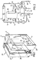
- FIG. 1 shows a perspective exploded view of a boiler in accordance with the present invention,
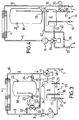
- FIG. 2 shows a simplified piping diagram of a first embodiment of the boiler of FIG. 1,
- FIG. 3 shows a simplified piping diagram of a second embodiment of the boiler of FIG. 1, and
- FIG. 4 shows a simplified piping diagram of a third embodiment of the boiler of FIG. 1.
- With reference to figures 1 and 2, numeral 1 indicates a so-called combined type boiler and in particular a wall boiler in accordance with a first embodiment of the present invention.
- The boiler 1 comprises a basically parallelepipedic vessel 2 equipped with a front control panel 3 comprising a known electronic control unit for control and regulation of the boiler.
- In the vessel 2 are conventionally supported the various components of the boiler 1 diagrammed in figure 2 and comprising a gas-water heat exchanger 4, designed for producing primary hot water for space heating, in fluid communication through a primary piping circuit 5 with
respective inlet opening 6 and outlet opening 7 respectively to and from the boiler and with a second water-water heat exchanger 8 designed for the producing hot sanitary water. - The primary piping circuit 5 comprises a
duct 9 for supplying primary water coming from a space heating circuit, not shown, to the gas-water heat exchanger 4 through aduct 37, as well as areturn duct 10 from said gas-water heat exchanger 4. - On the
ducts non-return valve 41 and valve means 11, e.g. a 3-way valve, designed to set up a fluid connection between the gas-water heat exchanger 4 and the water-water heat exchanger 8 or the external heating circuit alternately. - To this end, the primary piping circuit 5 comprises
respective ducts - A
duct 13 provides a fluid connection of the water-water heat exchanger 8 with thesupply duct 9, while apump 14 is provided in thissame supply duct 9 to promote circulation of the water in the primary piping circuit 5. - The water-
water heat exchanger 8 is also in fluid communication with asecondary piping circuit 15 for taking cold sanitary water from the water mains and sending hot sanitary water to the users, which comprises aninlet duct 16 and anoutlet duct 17 respectively to and from the water-water heat exchanger 8. - Said
ducts - In accordance with this first embodiment, the boiler 1 comprises a
heat accumulator 18, in this case a tank for accumulation of primary hot water, arranged in parallel with the gas-water heat exchanger 4. - Said
heat accumulator 18 is in fluid communication with the primary piping circuit 5 throughrespective ducts supply duct 9 and thereturn duct 10 of the gas-water heat exchanger 4. - A
pump 21 of the so-called reversible variable speed type, is mounted on theduct 20 and ensures circulation of the primary water from and to thetank 18, whilethermostats tank 18 and theducts -
Reference number 25 indicates a thermostat for instantaneous detection of the temperature of the sanitary hot water produced in the boiler 1. - In accordance with another advantageous feature of the present invention, the boiler 1 described above may be obtained from a pre-existing boiler of the combined type and with instantaneous sanitary hot water production, by connecting thereto a module indicated by 26 in figure 1 and incorporating the
heat accumulator 18. - If the boiler is of the wall-supported type as illustrated in figure 1, the
module 26 comprises a supportingframe 27 e.g. in parallelepipedic shape, provided with appropriate means for fastening to a wall and means for its connection to the frame of a pre-existing boiler with instantaneous sanitary water generation indicated by 29. - Advantageously, the above mentioned means may comprise a plurality of
hooks 28 onto which theboiler 29 can be hung by using the same means, such as e.g. abar 42 extending transversely on the back thereof, which allow its installation on a wall. - In the
module 26, theducts e.g. fittings heat accumulator tank 18 in the primary piping circuit of theboiler 29 in parallel with the gas-water heat exchanger 4. - If the
pre-existing boiler 29 is not provided with corresponding fittings on theducts heat accumulator tank 18 in the primary piping circuit can still be performed by an operation requiring minimal labour, quite within the capability of anyone skilled in the art. - The boiler 1 described hereinabove operates as follows.
- In the absence of sanitary water withdrawal, the temperature of the primary hot water accumulated in the
heat accumulator tank 18 is kept at a constant value thanks to the intervention of thethermostat 22 which, when it detects a decrease in water temperature, controls the boiler burner in such a way as to deliver the maximum thermal power to the gas-water heat exchanger 4, interrupts circulation of the primary hot water to the room heating circuit by stopping thepump 14 and promotes water circulation towards theheat accumulator tank 18 by activating thepump 21. - Under these conditions, the
non-return valve 41 ensures a correct fluid circulation from the gas-water heat exchanger 4 to the tank. - The primary hot water flows therefore in a closed circuit, defined in the primary piping circuit 5, where it flows in sequence: through the gas-water heat exchanger 4, a portion of the
return duct 10, theduct 20, thepump 21, theheat accumulator tank 18, theduct 19 and a portion of thesupply duct 9. - Upon reaching the desired temperature in the
heat accumulator tank 18, thethermostat 22 stops operation of thepump 21 and, if necessary, restores circulation of the primary hot water to the exterior of the boiler 1. - When hot water is drawn for sanitary use, a flow sensor - not shown - provided on the
inlet duct 16 activates in a known manner the burner and/orpump 14, if standing by, starts fluid circulation to the water-water heat exchanger 8 through the 3-way valve 11 and starts thepump 21 in the direction opposite the previous one, so as to withdraw a pre-set flowrate of primary hot water from theheat accumulator tank 18. - In accordance with an advantageous feature of the present invention, by controlling the flowrate delivered by the
pump 21 it is possible to draw from theheat accumulator tank 18 the minimum quantity of primary hot water necessary for reaching the desired temperature of the sanitary water. - The water withdrawn from the
heat accumulator tank 18 is mixed in the last portion of thereturn duct 10 and in theduct 12, with the primary hot water coming from the gas-water heat exchanger 4 and sent together therewith to the water-water heat exchanger 8. - The primary hot water coming from the water-
water heat exchanger 8 where it has transferred its heat to the sanitary hot water, therefore, branches in two parallel paths defined in the primary piping circuit 5: a first path including in sequence thesupply duct 9, the gas-water heat exchanger 4 and thereturn duct 10 and a second path including in sequence theduct 19, theheat accumulator tank 18, theduct 20 and thepump 21. - The amount of primary hot water withdrawal and hence the heat withdrawal from the
heat accumulator tank 18, is determined by thethermostat 25 which instantaneously detects the temperature of the sanitary water delivered by the boiler 1 and adjusts consequently the flowrate taken from thepump 21. - Thanks to the presence of the
thermostats heat accumulator tank 18. - Indeed, the
pump 21 is stopped when the temperature difference between the water entering theheat accumulator tank 18 and that which leaves the same, falls below a predetermined minimum value selected so as to ensure an adequate heat transfer to the cold sanitary water in the water-water heat exchanger 8. - When the withdrawal of sanitary water is ended and depending upon the temperature detected by the
thermostat 22, the boiler returns to the pre-existing operating conditions or again accumulates primary hot water in theheat accumulator tank 18 by the procedure set forth above. - In figures 3 and 4 are diagramatically shown additional embodiments of the boiler 1 in accordance with the present invention.
- In the following description and in said figures, the component parts of the boiler 1 structurally or functionally equivalent to those discussed above with reference to figures 1 and 2 are indicated by the same reference numbers and are not further described.
- In the embodiment illustrated in figure 3, the
variable speed pump 21, which may be of the non-reversible type as well, is mounted on theduct 19 on which is provided downstream thereof a 3-way valve 32. - From the latter depart two
other ducts supply duct 9 andreturn duct 10 of the gas-water heat exchanger 4. - Operation of this second embodiment of the boiler 1 is similar to that discussed above.
- In the accumulation step of the primary hot water in the
heat accumulator tank 18, said water flows in a closed circuit defined in the primary piping circuit 5 which comprises in sequence: the gas-water heat exchanger 4, a portion ofreturn duct 10, theduct 20, theheat accumulator tank 18, thepump 21, the 3-way valve 32, theduct 33 and a portion of thesupply duct 9. - When hot water is drawn for sanitary use, the flow sensor provided on the
inlet duct 16 in addition to activating the burner and/or thepump 14, if on stand-by, starts thevariable speed pump 21 and switches the water flow drawn from theheat accumulator tank 18 to theduct 34 through the 3-way valve 32. - According to this embodiment, there are two different operating conditions of the bolier 1 when a
variable speed pump 21 having a maximum flowrate equal to that of thepump 14 is provided and depending on the quantity of water drawn from theheat accumulator tank 18. - In a first operating condition, in which the flowrate of the
variable speed pump 21 is less than that of thepump 14, the water taken from thetank 18 is mixed - in the last portion of theduct 10 and in the duct 12 - with the primary hot water coming from the gas-water heat exchanger 4 and is sent together with the latter to the water-water heat exchanger 8. - The primary hot water coming from the latter exchanger, where it has transfered its heat to the sanitary hot water, subsequently branches in two parallel paths defined in the primary circuit 5: a first path including in sequence the
entire duct 9, the gas-water heat exchanger 4 and theduct 10 and a second path including in sequence theduct 20, thetank 18, thepump 21, the 3-way valve 32 and theduct 34. - In this first operating condition, therefore, the gas-water heat exchanger 4 and the
tank 18 are connected together in parallel. - In a second operating condition, in which the flow rate of the
pump 21 is equal to that of thepump 14, the primary water circulates in a single path including in sequence theentire duct 9, the gas-water heat exchanger 4 and a first portion of theduct 10, theduct 20, thetank 18, thepump 21, the 3-way valve 32, theduct 34 and then a last portion of theduct 10. - In this second operating condition, the gas-water heat exchanger 4 and the
tank 18 are therefore connected in series with one another: the primary water heated by the gas-water heat exchanger 4 is sent entirely into thetank 18 where it replaces the accumulated hot water delivered to the water-water heat exchanger 8 by thepump 21. - In both operating conditions, the amount of primary hot water drawn and hence the heat withdrawal from the
tank 18, is determined by thethermostat 25 which instantaneously detects the temperature of the sanitary water delivered by the boiler 1 and, based thereon, adjusts the flowrate withdrawn by thepump 21. - Similarly to the previous embodiment, in this case as well the withdrawal of the water accumulated in the
tank 18 is interrupted when the temperature difference between the water entering and leaving thetank 18, measured in this case by thethermostats - In accordance with the present invention, the
duct 34 of the boiler illustrated in figure 3 can be connected directly to theinlet duct 12 leading to the water-water heat exchanger 8, bypassing the 3-way valve 11 as shown e.g. with dot and dash lines in figure 3. - Thanks to this structural feature, the boiler of the present invention allows heating of the sanitary water for small withdrawals by using exclusively the heat accumulated in the
tank 18 and without interrupting the primary hot water delivery to the heating circuit outside the boiler or without starting the boiler burner. - In this case, it is advantageously possible to have both space heating and simultaneous production of hot sanitary water or, in the alternative, production of hot sanitary water while the burner is turned off.
- In this second embodiment of the present invention, the
module 26 obviously comprises the additional elements provided therein, i.e. the 3-way valve 32 and theducts - In the embodiment illustrated in figure 4, the primary hot water accumulation tank is arranged in the primary piping circuit 5 in series to the gas-water heat exchanger 4.
- According to this embodiment, a 3-
way valve 36 and a cut-off valve 35 are mounted on theducts - The
outlet duct 13 for supplying hot water for space heating from the water-water heat exchanger 8 and theduct 9 for connection to the gas-water heat exchanger 4, are also connected to the 3-way valve 36. - In accordance with this embodiment, the
tank 18 is respectively connected to thereturn duct 10 and to theduct 37 throughducts - Furthermore, on the
duct 40 is provided a one-way valve 39 to allow a water flow exclusively towards theduct 37. - When no hot sanitary water is withdrawn, the temperature of the primary hot water accumulated in the
tank 18 is held steady thanks to the intervention of thethermostat 22 which, upon each lowering of water temperature, controls the boiler burner so as to deliver the maximum thermal power to the gas-water heat exchanger 4, interrupts fluid circulation to the heating circuit through the cut-off valve 35 and switches the 3-way valve 36 so as to allow fluid communication between theducts - The primary hot water, therefore, flows in a first path, defined in the primary circuit 5, including in sequence: the gas-water heat exchanger 4, a portion of the
duct 10, theduct 20, thetank 18, theduct 40, the one-way valve 39, theduct 37, the 3-way valve 36, thepump 14 and theduct 9 up to the gas-water heat exchanger 4. - When hot water is withdrawn for sanitary use, the flow sensor provided in the
duct 16 activates in a known manner the burner and/or thepump 14, if on stand-by, and switches the 3-way valve 36 so as to allow fluid communication between theducts - The primary hot water transfers its heat to the hot sanitary water in the water-
water heat exchanger 8 circulating in a second path, defined in the primary circuit 5 and including in sequence: the gas-water heat exchanger 4, theduct 10, theduct 20, thetank 18, theduct 19, the water-water heat exchanger 8, theduct 13, the 3-way valve 36, thepump 14 and theduct 9. - In accordance with this embodiment of the present invention, the primary water heated by the gas-water heat exchanger 4 is sent into the
tank 18 where it replaces the accumulated hot water delivered to the water-water heat exchanger 8 by thepump 14. - In this case as well, control of the heat transfer by the accumulated hot water to the sanitary water is achieved by the
thermostat 25 which adjusts the flowrate of thepump 14 and the thermal power delivered by the burner to the gas-water heat exchanger 4. - After drawing of sanitary water and after having restored the temperature of the accumulated water to the desired value, the boiler 1 may send again, if necessary, hot water to the space heating circuit after activation of the
pump 14 and switching of the 3-way valve 36 so as to allow fluid communication between theducts - The numerous advantages achieved by the present invention are evident from the description hereinabove.
- The boiler 1 in accordance with the present invention allows, differently from conventional accumulation boilers, an extremely flexible temperature control of the delivered sanitary water, by mere control of the flowrate of hot water withdrawn from the accumulation tank.
- Indeed, by metering appropriately the accumulated hot water into that produced instantaneously in the gas-water heat exchanger, it is possible to control the heat transferred to the sanitary water and hence the temperature of the latter in a broad range of values and in a manner which is in first approximation independent from the temperature of the accumulated hot water.
- By controlling the flowrate of hot water drawn from the accumulation tank there is also the further advantage of a gradual use of the heat stored therein, which is in any case limited to the minimum amount required.
- The boiler of the present invention allows therefore an optimal use of the accumulated heat, which can be gradually delivered to meet in an extremely flexible and lasting manner the most varied hot sanitary water withdrawal requirements.
- Furthermore, since the accumulation of heat takes place by means of the primary water, the temperature reachable in the tank 18 (up to 85-90°C) and hence the quantity of thermal energy stored, are much greater than the maximums allowed by conventional accumulation boilers, where said temperature is limited by the known problems of calcareous deposits build-up.
- The boiler of the present invention can consequently meet high withdrawals of hot sanitary water for a longer time, i.e. occupy less space for a given performance.
- Accumulation of heat by means of primary water, which flows in a circuit operated at relatively low pressure, allows to achieve the important additional advantages from a structural viewpoint as well.
- The accumulation tank, in fact, is substantially maintenance-free and is entirely free of all those structural, hygienic and sanitary requirements which standards impose on accumulation tanks for hot sanitary water of conventional boilers.
- Said tank may therefore be manufactured in carbon steel and in the most varied shapes so as to make the best possible use of the space available.
- Thanks to the provision of a module connectable to already installed boilers with an instant hot sanitary water production, the present invention also allows to achieve the advantages mentioned above with minimal use of labour and at relatively low cost.
- Lastly, the boiler of the present invention comprises elements of extremely simple construction which can be mass produced at low unit cost.
Claims (13)
- Boiler of the so-called combined type comprising a first gas-water heat exchanger (4) for producing primary hot water for space heating, a primary water piping circuit (5) for circulation of said water extending between respective inlet and outlet openings (6, 7) of the boiler, a second water-water heat exchanger (8) for producing hot sanitary water, as well as valve means (11, 36) for selectively diverting said primary hot water to said second water-water heat exchanger (8) or to said outlet opening (7),
characterised in that it further comprises a heat accumulator (18), structurally independent of said second water-water heat exchanger (8), means being provided to allow heat exchange between said heat accumulator (18) and said second water-water heat exchanger (8). - Boiler according to claim 1, characterised in that said heat accumulator (18) comprises an accumulation tank for said primary hot water.
- Boiler according to claim 2, characterised in that said heat accumulator tank (18) is arranged in the primary water piping circuit (5) in parallel or in series with said first gas-water heat exchanger (4).
- Boiler according to claim 3, characterised in that the means allowing heat exchange between the heat accumulator tank (18) and the second water-water heat exchanger (8) comprises hot water inlet and outlet ducts (19, 20) to and from said heat accumulator (18) tank, respectively connected with primary hot water supply and return ducts (9, 10) to and from said gas-water heat exchanger (4), and a pump (21) on said outlet duct (20) from the heat accumulator tank (18).
- Boiler according to claim 3, characterised in that the means allowing heat exchange between the heat accumulator tank (18) and the second water-water heat exchanger (8) comprises an inlet duct (20) and a pair of hot water outlet ducts (33, 34) from said heat accumulator tank (18), respectively connected with a return duct (10) and with either a primary hot water supply and return ducts (9, 10) to and from respectively said gas-water heat exchanger (4), means being provided for selectively diverting the accumulated hot water in the heat accumulator tank (18) to one or the other of said outlet ducts (33, 34).
- Boiler according to claim 3, characterised in that the means allowing heat exchange between the heat accumulator tank (18) and the second water-water heat exchanger (8) comprises a first duct (20) extending between said heat accumulator tank (18) and a primary hot water return duct (10) from the gas-water heat exchanger (4) and a pair of ducts (33, 34) respectively providing fluid communication between said heat accumulator tank (18) with a primary hot water supply duct (9) to the gas-water heat exchanger (4) and with said second water-water heat exchanger (8), means being provided for selectively diverting the accumulated hot water in the heat accumulator tank (18) to one or the other of said ducts (33, 34).
- Boiler according to claims 5 or 6, characterised in that said means of selectively diverting the accumulated hot water further comprises a pump (21) and a 3-way valve (32) downstream from said heat accumulator tank (18).
- Boiler according to claim 3, characterised in that the means allowing heat exchange between the heat accumulator tank (18) and the second water-water heat exchanger (8) comprises primary hot water inlet and outlet ducts (20, 19) to and from said heat accumulator tank (18) and a by-pass duct (40) extending between said outlet duct (19) and a primary hot water supply duct (37) to said gas-water heat exchanger (4), as well as valve means (35) for cut-off of a primary hot water return duct (10) from said gas-water heat exchanger (4).
- Module (26) for the conversion of a boiler (29) of the so-called combined type with instantaneous production of sanitary water into a boiler according to any one of the preceding claims, said boiler (29) comprising a first gas-water heat exchanger (4) for producing primary hot water for space heating, a primary water piping circuit (5) for circulation of said primary hot water extending between an inlet opening (6) and outlet opening (7) of the boiler, a second water-water heat exchanger (8) for producing hot sanitary water, as well as valve means (11, 36) for selectively diverting said primary hot water to said second water-water heat exchanger (8) or to said outlet opening (7), characterised in that it comprises a supporting frame (27) provided with means for connection to said boiler (29), a heat accumulator (18) and means for installing said heat accumulator (18) in said primary water piping circuit (5) in series or parallel with said first gas-water heat exchanger (4).
- Module (26) according to claim 9, characterised in that said heat accumulator (18) comprises a tank for accumulation of primary hot water generated in said first gas-water heat exchanger (4).
- Module (26) according to claim 9, characterised in that said connecting means to the boiler comprises a plurality of hooks (28).
- Module (26) according to claim 10, characterised in that said means for fluid connection between said tank (18) and said second water-water heat exchanger (8) comprises an inlet duct (19, 20) and at least one primary hot water outlet duct (19, 20, 33, 34) from said heat accumulator tank provided with respective fittings (30, 31), as well as a pump (21) on said at least one outlet duct (19, 20, 33, 34) from the heat accumulator tank (18).
- Module (26) according to claim 12, characterised in that said means for fluid connection between said heat accumulator tank (18) and said second water-water heat exchanger (8) further comprises a 3-way valve (32) downstream of said pump (21).
Applications Claiming Priority (2)
| Application Number | Priority Date | Filing Date | Title |
|---|---|---|---|
| ITMI931603A IT1272474B (en) | 1993-07-20 | 1993-07-20 | BOILER OF THE SO-CALLED COMBINED HEAT ACCUMULATION TYPE. |
| ITMI931603 | 1993-07-20 |
Publications (1)
| Publication Number | Publication Date |
|---|---|
| EP0635682A1 true EP0635682A1 (en) | 1995-01-25 |
Family
ID=11366641
Family Applications (1)
| Application Number | Title | Priority Date | Filing Date |
|---|---|---|---|
| EP94110862A Withdrawn EP0635682A1 (en) | 1993-07-20 | 1994-07-13 | Boiler of the so-called combined heat accumulation type |
Country Status (2)
| Country | Link |
|---|---|
| EP (1) | EP0635682A1 (en) |
| IT (1) | IT1272474B (en) |
Cited By (16)
| Publication number | Priority date | Publication date | Assignee | Title |
|---|---|---|---|---|
| GB2293438A (en) * | 1994-09-20 | 1996-03-27 | Gledhill Water Storage | The control of water heating apparatus to prevent scalding |
| AT402662B (en) * | 1995-04-03 | 1997-07-25 | Vaillant Gmbh | HEATING SYSTEM WITH A BURNER HEATED HEATING SYSTEM WITH A BURNER HEATED PRIMARY HEAT EXCHANGER PRIMARY HEAT EXCHANGER |
| WO1997036138A1 (en) * | 1996-03-27 | 1997-10-02 | Alf Ottosson | Method and device for temperature control of hot tap-water |
| EP0916901A1 (en) * | 1997-11-11 | 1999-05-19 | IABER S.p.A. | Scale reducing device for gas-fired boilers |
| EP0843133A3 (en) * | 1996-11-15 | 1999-10-27 | Richard Vetter | Water heating apparatus |
| EP1026449A1 (en) * | 1999-02-03 | 2000-08-09 | IABER S.p.A. | Maximum flow boiler |
| FR2817610A1 (en) * | 2000-12-05 | 2002-06-07 | Dietrich Thermique | Circuit, for preparing sanitary water to be used in heater, comprises small container, sanitary heat exchanger, principal heat exchanger and short circuiting channel in parallel with container |
| WO2003014627A1 (en) * | 2001-08-10 | 2003-02-20 | Queen's University At Kingston | Passive back-flushing thermal energy system |
| CN1111272C (en) * | 1999-08-08 | 2003-06-11 | 许富昌 | Method for counting consumed calories of user with hot water flowmeter for centralized heating system |
| WO2003098118A3 (en) * | 2002-05-17 | 2004-04-29 | Vebteck Res Inc | Combined heating and hot water system |
| EP1528328A1 (en) * | 2003-11-03 | 2005-05-04 | Grundfos A/S | Assembly for a compact heating installation |
| EP1577615A1 (en) * | 2004-03-17 | 2005-09-21 | Martin Sandler Systemtechnik E.K. | Method and apparatus for providing hot domestic water with a heat exchanging device |
| EP1617149A1 (en) * | 2004-07-14 | 2006-01-18 | BERTOLI, Marco | Instant boiler for heating water |
| WO2013165106A1 (en) * | 2012-05-03 | 2013-11-07 | 주식회사 경동나비엔 | Boiler having increased indoor heating efficiency and enabling simultaneous use of indoor heating and hot water |
| WO2014051268A1 (en) * | 2012-09-28 | 2014-04-03 | 주식회사 경동나비엔 | Structure for controlling temperature of hot- water supply from waste heat recovery system using three-way valve or mixing valve, and structure for controlling temperature of hot- water supply from waste heat recovery system using heat exchanger in hot- water tank |
| EP1801507A3 (en) * | 2005-08-03 | 2015-09-02 | Eco heating systems B.V. | Device for dispensing a heated fluid and heating device therefore |
Citations (3)
| Publication number | Priority date | Publication date | Assignee | Title |
|---|---|---|---|---|
| CH180906A (en) * | 1935-01-09 | 1935-11-30 | Ctc Ab | Hot water supply system with indirect heating of the tap water in a pipe system. |
| DE4236967A1 (en) * | 1991-11-04 | 1993-05-06 | Joh. Vaillant Gmbh U. Co, 5630 Remscheid, De | Heating system with circulating pump - has hot-water storage tank in series with primary branch of heat-exchanger |
| GB2262593A (en) * | 1991-12-17 | 1993-06-23 | Inter Albion Ltd | An apparatus for and method of providing hot sanitary water |
-
1993
- 1993-07-20 IT ITMI931603A patent/IT1272474B/en active IP Right Grant
-
1994
- 1994-07-13 EP EP94110862A patent/EP0635682A1/en not_active Withdrawn
Patent Citations (3)
| Publication number | Priority date | Publication date | Assignee | Title |
|---|---|---|---|---|
| CH180906A (en) * | 1935-01-09 | 1935-11-30 | Ctc Ab | Hot water supply system with indirect heating of the tap water in a pipe system. |
| DE4236967A1 (en) * | 1991-11-04 | 1993-05-06 | Joh. Vaillant Gmbh U. Co, 5630 Remscheid, De | Heating system with circulating pump - has hot-water storage tank in series with primary branch of heat-exchanger |
| GB2262593A (en) * | 1991-12-17 | 1993-06-23 | Inter Albion Ltd | An apparatus for and method of providing hot sanitary water |
Cited By (25)
| Publication number | Priority date | Publication date | Assignee | Title |
|---|---|---|---|---|
| GB2293438A (en) * | 1994-09-20 | 1996-03-27 | Gledhill Water Storage | The control of water heating apparatus to prevent scalding |
| AT402662B (en) * | 1995-04-03 | 1997-07-25 | Vaillant Gmbh | HEATING SYSTEM WITH A BURNER HEATED HEATING SYSTEM WITH A BURNER HEATED PRIMARY HEAT EXCHANGER PRIMARY HEAT EXCHANGER |
| WO1997036138A1 (en) * | 1996-03-27 | 1997-10-02 | Alf Ottosson | Method and device for temperature control of hot tap-water |
| AU703631B2 (en) * | 1996-03-27 | 1999-03-25 | Alf Ottosson | Method and device for temperature control of hot tap-water |
| EP0843133A3 (en) * | 1996-11-15 | 1999-10-27 | Richard Vetter | Water heating apparatus |
| EP0916901A1 (en) * | 1997-11-11 | 1999-05-19 | IABER S.p.A. | Scale reducing device for gas-fired boilers |
| EP1026449A1 (en) * | 1999-02-03 | 2000-08-09 | IABER S.p.A. | Maximum flow boiler |
| CN1111272C (en) * | 1999-08-08 | 2003-06-11 | 许富昌 | Method for counting consumed calories of user with hot water flowmeter for centralized heating system |
| FR2817610A1 (en) * | 2000-12-05 | 2002-06-07 | Dietrich Thermique | Circuit, for preparing sanitary water to be used in heater, comprises small container, sanitary heat exchanger, principal heat exchanger and short circuiting channel in parallel with container |
| WO2003014627A1 (en) * | 2001-08-10 | 2003-02-20 | Queen's University At Kingston | Passive back-flushing thermal energy system |
| US6827091B2 (en) | 2001-08-10 | 2004-12-07 | Queen's University At Kingston | Passive back-flushing thermal energy system |
| US7171972B2 (en) | 2001-08-10 | 2007-02-06 | Queen's University At Kingston | Passive back-flushing thermal energy system |
| US7823628B2 (en) | 2001-08-10 | 2010-11-02 | Queen's University At Kingston | Passive back-flushing thermal energy system |
| WO2003098118A3 (en) * | 2002-05-17 | 2004-04-29 | Vebteck Res Inc | Combined heating and hot water system |
| EP1528328A1 (en) * | 2003-11-03 | 2005-05-04 | Grundfos A/S | Assembly for a compact heating installation |
| EP1909041A1 (en) * | 2003-11-03 | 2008-04-09 | Grundfos a/s | Component for a compact heating system |
| EP1577615A1 (en) * | 2004-03-17 | 2005-09-21 | Martin Sandler Systemtechnik E.K. | Method and apparatus for providing hot domestic water with a heat exchanging device |
| EP1617149A1 (en) * | 2004-07-14 | 2006-01-18 | BERTOLI, Marco | Instant boiler for heating water |
| EP1801507A3 (en) * | 2005-08-03 | 2015-09-02 | Eco heating systems B.V. | Device for dispensing a heated fluid and heating device therefore |
| WO2013165106A1 (en) * | 2012-05-03 | 2013-11-07 | 주식회사 경동나비엔 | Boiler having increased indoor heating efficiency and enabling simultaneous use of indoor heating and hot water |
| CN104272030A (en) * | 2012-05-03 | 2015-01-07 | 庆东纳碧安株式会社 | Boiler having increased indoor heating efficiency and enabling simultaneous use of indoor heating and hot water |
| CN104272030B (en) * | 2012-05-03 | 2017-05-10 | 庆东纳碧安株式会社 | Boiler having increased indoor heating efficiency and enabling simultaneous use of indoor heating and hot water |
| US9869490B2 (en) | 2012-05-03 | 2018-01-16 | Kyungdong Navien Co., Ltd. | Boiler having increased indoor heating efficiency and enabling simultaneous use of indoor heating and hot water |
| WO2014051268A1 (en) * | 2012-09-28 | 2014-04-03 | 주식회사 경동나비엔 | Structure for controlling temperature of hot- water supply from waste heat recovery system using three-way valve or mixing valve, and structure for controlling temperature of hot- water supply from waste heat recovery system using heat exchanger in hot- water tank |
| AU2013320791B2 (en) * | 2012-09-28 | 2016-01-07 | Kyungdong Navien Co., Ltd. | Structure for controlling temperature of hot- water supply from waste heat recovery system using three-way valve or mixing valve, and structure for controlling temperature of hot- water supply from waste heat recovery system using heat exchanger in hot- water tank |
Also Published As
| Publication number | Publication date |
|---|---|
| ITMI931603A0 (en) | 1993-07-20 |
| IT1272474B (en) | 1997-06-23 |
| ITMI931603A1 (en) | 1995-01-20 |
Similar Documents
| Publication | Publication Date | Title |
|---|---|---|
| EP0635682A1 (en) | Boiler of the so-called combined heat accumulation type | |
| EP1957876B1 (en) | Heating system | |
| CA2080946C (en) | Hot water storage system | |
| US11002492B2 (en) | Energy storage system | |
| EP0422738B1 (en) | Apparatus for dispensing quantities of water of variable temperatures | |
| EP0820543B1 (en) | Iron arrangement | |
| EP0692682B1 (en) | Boiler device in particular of the so-called combined type with prompt delivery of hot sanitary water | |
| EP0740113A1 (en) | Combined heating boiler with improved performance | |
| KR19990076959A (en) | Heating device and how it works | |
| EP1983267A2 (en) | Heating system with solar energy and heating method carried out by means of the same | |
| EP0355881B1 (en) | Tap-water heating device | |
| JP2004020013A (en) | Hot water storage type hot water supply device | |
| AU635027B2 (en) | Improvements to hot water tanks and installations equipped with such tanks | |
| EP1039236A2 (en) | Storage boiler of the combined type | |
| EP0940636B1 (en) | Boiler for heating and for producing sanitary hot water | |
| KR200370859Y1 (en) | Water Supply System for Heating and Domestic Hot Water | |
| CN108800267A (en) | Electric heating phase-changing energy-storing thermal power plant unit and its variable working condition energy adjustment method | |
| CN215765779U (en) | Domestic full premix condensation hanging stove and heat storage water tank all-in-one | |
| CN219390100U (en) | Heating device and water heater | |
| CZ20022816A3 (en) | Water heating method and heater for making the same | |
| KR100603962B1 (en) | Water Supply System for Heating and Domestic Hot Water | |
| JPS60155855A (en) | Hot-water heater | |
| EP0943877A2 (en) | A domestic water heater | |
| EP0509611A1 (en) | Combined central-heating and water-heating boiler comprising a heat exchanger with built-in pumps | |
| AU2021204164A1 (en) | Water heating system |
Legal Events
| Date | Code | Title | Description |
|---|---|---|---|
| PUAI | Public reference made under article 153(3) epc to a published international application that has entered the european phase |
Free format text: ORIGINAL CODE: 0009012 |
|
| AK | Designated contracting states |
Kind code of ref document: A1 Designated state(s): DE ES FR GB IT NL |
|
| RAP1 | Party data changed (applicant data changed or rights of an application transferred) |
Owner name: INTEGRA S.R.L. |
|
| 17P | Request for examination filed |
Effective date: 19950713 |
|
| 17Q | First examination report despatched |
Effective date: 19970606 |
|
| STAA | Information on the status of an ep patent application or granted ep patent |
Free format text: STATUS: THE APPLICATION IS DEEMED TO BE WITHDRAWN |
|
| 18D | Application deemed to be withdrawn |
Effective date: 19971017 |