EP0635677A1 - Flammenhalterplatte für Gasbrenner, Verfahren zu seiner Herstellung und Brenner mit einer solchen Platte - Google Patents
Flammenhalterplatte für Gasbrenner, Verfahren zu seiner Herstellung und Brenner mit einer solchen Platte Download PDFInfo
- Publication number
- EP0635677A1 EP0635677A1 EP94401586A EP94401586A EP0635677A1 EP 0635677 A1 EP0635677 A1 EP 0635677A1 EP 94401586 A EP94401586 A EP 94401586A EP 94401586 A EP94401586 A EP 94401586A EP 0635677 A1 EP0635677 A1 EP 0635677A1
- Authority
- EP
- European Patent Office
- Prior art keywords
- plate
- network
- strip
- compressed
- sections
- Prior art date
- Legal status (The legal status is an assumption and is not a legal conclusion. Google has not performed a legal analysis and makes no representation as to the accuracy of the status listed.)
- Granted
Links
Images


Classifications
-
- F—MECHANICAL ENGINEERING; LIGHTING; HEATING; WEAPONS; BLASTING
- F23—COMBUSTION APPARATUS; COMBUSTION PROCESSES
- F23D—BURNERS
- F23D14/00—Burners for combustion of a gas, e.g. of a gas stored under pressure as a liquid
- F23D14/46—Details
- F23D14/48—Nozzles
- F23D14/58—Nozzles characterised by the shape or arrangement of the outlet or outlets from the nozzle, e.g. of annular configuration
-
- F—MECHANICAL ENGINEERING; LIGHTING; HEATING; WEAPONS; BLASTING
- F23—COMBUSTION APPARATUS; COMBUSTION PROCESSES
- F23D—BURNERS
- F23D14/00—Burners for combustion of a gas, e.g. of a gas stored under pressure as a liquid
- F23D14/02—Premix gas burners, i.e. in which gaseous fuel is mixed with combustion air upstream of the combustion zone
-
- F—MECHANICAL ENGINEERING; LIGHTING; HEATING; WEAPONS; BLASTING
- F23—COMBUSTION APPARATUS; COMBUSTION PROCESSES
- F23D—BURNERS
- F23D14/00—Burners for combustion of a gas, e.g. of a gas stored under pressure as a liquid
- F23D14/46—Details
-
- F—MECHANICAL ENGINEERING; LIGHTING; HEATING; WEAPONS; BLASTING
- F23—COMBUSTION APPARATUS; COMBUSTION PROCESSES
- F23D—BURNERS
- F23D2203/00—Gaseous fuel burners
- F23D2203/10—Flame diffusing means
- F23D2203/101—Flame diffusing means characterised by surface shape
- F23D2203/1012—Flame diffusing means characterised by surface shape tubular
-
- F—MECHANICAL ENGINEERING; LIGHTING; HEATING; WEAPONS; BLASTING
- F23—COMBUSTION APPARATUS; COMBUSTION PROCESSES
- F23D—BURNERS
- F23D2203/00—Gaseous fuel burners
- F23D2203/10—Flame diffusing means
- F23D2203/103—Flame diffusing means using screens
-
- F—MECHANICAL ENGINEERING; LIGHTING; HEATING; WEAPONS; BLASTING
- F23—COMBUSTION APPARATUS; COMBUSTION PROCESSES
- F23D—BURNERS
- F23D2900/00—Special features of, or arrangements for burners using fluid fuels or solid fuels suspended in a carrier gas
- F23D2900/00019—Outlet manufactured from knitted fibres
Definitions
- the invention relates to a flame attachment plate, usable in particular on gas mixture burners.
- They are made of various materials, such as ceramic or metal, and are generally pierced with orifices of suitable size and distribution to allow the passage of gases and their combustion. They are arranged in the gas burner between the distribution and combustion chambers, which they separate.
- Such pierced plates still pose problems related to their mounting because they are in fact often made up of several thin plates which must be stacked on top of each other in the burner. This poses adjustment problems between the plates and induces a high installation cost.
- the object of the invention is to solve these difficulties by means of an improved flame attachment plate, allowing in particular an effective stabilization and a good distribution of the flames over its entire surface, with the formation of a substantially uniform flame front, favoring, in addition, limiting the risk of backfire.
- the plate according to the invention causes a relatively low pressure drop of approximately 35 to 50 Pa and promotes the limitation of the quantities of harmful gases emitted (carbon oxides, nitrogen, etc.).
- the proposed solution consists of a plate having passages passing through it for the circulation through it of the gases to be burned, the plate of the invention being characterized in that it comprises, in its constitution, a compressed network of wire (s) with interlaced parts forming between them said gas passages.
- the invention notably allows, by its structure or texture in wire (s) with interlaced parts, a substantially uniformly distributed passage of gases over the entire surface of the plate, with regular spreading of the flame created, rendering possible in practice (for example in the case of heating installations), to advantageously reduce the spacing between the flame attachment zone and the heat exchanger often associated with the burner, since the flame front can be relatively low height.
- the invention also relates to a burner of the general gas mixture type, comprising a distribution chamber supplied with combustion air and combustible gas, communicating with a combustion chamber, with interposition between them of the plate according to the invention.
- the plate of the invention can be used in particular for domestic burners, such as, for example, blown air, total premix and blue flame, making possible in particular a large modulation in power, which can, for example, go from '' approximately 3 to 33 kilowatts, or a power modulation of 1: 11, with a pfd which can range from 225 to 2500 kw / cm2, approximately.
- domestic burners such as, for example, blown air, total premix and blue flame
- a large modulation in power which can, for example, go from '' approximately 3 to 33 kilowatts, or a power modulation of 1: 11, with a pfd which can range from 225 to 2500 kw / cm2, approximately.
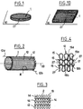
- this plate or sieve distribution can have a shape for example of substantially circular section (Figure 1) or rectangular parallelepiped ( Figure 10), with dimensions adapted to those of the associated burner.
- the plate comprises, in its constitution, a network 2 of flexible wire (s) 12, with intertwined or entangled parts, providing between them passages 27 or channels passing through the plate for the gas flow through it. It appears that the entanglement of the parts of wire (s) of the network, when the latter is in a compressed state, likewise that the shape, size and position of the gas passage orifices within the plate are random and depend on the force which has been exerted on the network to compress it.
- This network of thread (s) or interlacing 2 is presented here as a knitted work 10 consisting of at least one flexible thread.
- this knitted work is made of a single yarn 12 extending continuously between its free ends 12a and 12b ( Figure 2).
- This wire may be made of a ductile metallic material which is easily knitted, such as for example "304L" stainless steel two tenths of a millimeter in diameter.
- the material used to make the plate should preferably retain its characteristics (mechanical in particular) up to high temperatures, of the order of about 1000 ° C to 1200 ° C.
- FIG 3 there is schematically illustrated how the loops 19 in " ⁇ " (OMEGA) of the wire 12 can intertwine with each other, defining stitches 14, of suitable dimensions.
- These meshes (corresponding to the aforementioned passages 27) being advantageously relatively loose at the origin, the mesh produced can be easily deformed in different directions at the start of the shaping of the plate.
- FIG. 4 shows more precisely the intertwining of the sections or parts 15 of the wire, which overlap upside down, thus presenting intertwining zones as referenced at 17, these sections forming “upper” loops 19a which pass through the loops below them 19b, thus delimiting the passages 27.
- these passages of the knitted work have been shown in a relatively loose state, these same passages being found distributed throughout the structure of the network in the compressed state according to shape, size and arrangement function of the compressive forces exerted.
- a knitted work 10 in the form of a cylindrical tube ( Figure 2), deformable and compressible.
- This tube is first of all flattened or flattened along two fold lines 16, 18, both substantially parallel to the longitudinal axis 20 of this tube, the knitted work then having the general shape of a strip 21 of double thickness .
- the strip obtained is then wound on itself, from one of its ends 21a.
- FIG. 6 it can be seen that the roll 22 formed, of axis 25 substantially perpendicular to the longitudinal axis 46 of the strip, is advantageously produced by tightening the strip well when it is wound on itself.
- This winding 22 is then compressed substantially uniformly along its axis 25, in the direction of the arrows F a and F ' a , and possibly in the case where this compression along the axis 25 is insufficient, also perpendicularly to this axis 25 in the direction of the arrows Fr, until the compressed network constituting the desired plate is obtained such as that of FIG. 1, which compressed network preserves between its parts of wire (s) the passages, although deformed, intended for the circulation of gases .
- the axial compression will first be applied, then, if necessary, the radial compression. Note that here the compression is therefore carried out substantially parallel and perpendicular to the surface of the plate thus formed.
- the plate, whose orifices 27 for the passage of gases will thus be randomly distributed over its entire surface, will in particular allow effective self-stabilization of the flame.
- FIG. 7 Another possibility of making this plate is shown in FIG. 7, with a view for example to obtaining the plate in the form of a substantially quadrilateral in FIG. 10.
- the strip is folded several times on itself in a stacking direction of the folds 45 in the manner of an accordion, constituting a series of folds of which only the upper fold has been referenced at 42 , the folds can be arranged substantially parallel to the plane 30 of the plate thus formed.
- This fold 40 is then compressed, being advantageously subjected to a first compression substantially along the stacking axis 45 of the folds in the direction of the arrows F a and F ' a , then if desired a second compression, substantially perpendicular to this same axis 45, in the direction of the arrows F l .
- the plate 1 as illustrated in FIG. 8, provision could also be made for it to consist of a stack 40a of sections 42a pre-cut from the strip 21, all of substantially equal dimensions, this stack then being compressed substantially parallel, and incidentally, perpendicular to the stacking axis 45a of these sections.
- the parts or sections 42a of the stacked strip will be oriented substantially parallel to the plane 30 of the plate, the axis 45a then being substantially perpendicular to this plane.
- the dimensions of the knitted work 10, as well as of the roller 22 of the folding 40, or of the stack 40a, will be adapted so that, after compression, the dimensions of the plate correspond substantially to those of the associated burner .
- a flame hooking plate of circular shape
- this roller is then subjected to a substantially axial pressure (Fa, Fa ') to reduce the height of the plate to about 15 mm.
- a metal banding (not shown) may allow the plate to be held around its periphery.
- a plate 1 mounted in a burner of known type, referenced as a whole at 80, such as for example a domestic air burner, premixed total and blue flame.
- This burner 80 essentially comprises a distribution chamber 81, which has the general shape of a truncated cone box, of substantially circular section, connected at its narrowest rear face 81a to separate supply lines 83, 84 in combustion air and combustible gas respectively.
- This distribution chamber 81 is delimited transversely, on its front face, by the flame attachment plate 1.
- this plate is in the form of a substantially circular disc, mounted in a hoop 90 whose dimensions are adapted to those of the burner to which it is fixed by any means known to those skilled in the art, the plate being disposed substantially perpendicular to the axis 86 of the chamber 81 so as to separate the latter from the combustion chamber 82.
- the letters AV and AR make it possible to locate the sides "front” and “rear” of the burner, respectively, with reference to the circulation of the combustible mixture, in the burner, as shown diagrammatically by the arrows 87, 87 ' and 88.
- the line 84 for supplying combustible gas meets the line 83 for air supply just upstream from the distribution chamber (at 85).
- the ignition of the burner is ensured by an electrode 97 suitably insulated and supplied under high voltage, by a power cable not shown, the ignition being effected by sparks or electric arc between the tip 97a of the 'electrode and, for example, the wall next to the plate (if the latter is metallic) or the wall of the combustion chamber, or even the grid 1 itself.
- the screened structure or plate 1 of stainless steel reference "304L" may have a diameter of approximately 130 mm and a thickness of approximately 15 mm to be installed in a domestic burner whose distribution chamber consists of a truncated cone of approximately 95 mm in height. It was found that in operation the maximum pressure drop created by the combustion head 1 is relatively low, of the order of 50 Pa, the maximum temperature at the outlet 1a of the plate 1 at stoichiometry being 750 ° C; furthermore, no significant noise pollution was observed. It will be noted that the plate according to the invention can be mounted on gas premix burners as well as on burners without premix.
Landscapes
- Engineering & Computer Science (AREA)
- Chemical & Material Sciences (AREA)
- Combustion & Propulsion (AREA)
- Mechanical Engineering (AREA)
- General Engineering & Computer Science (AREA)
- Gas Burners (AREA)
Applications Claiming Priority (2)
| Application Number | Priority Date | Filing Date | Title |
|---|---|---|---|
| FR9308827 | 1993-07-19 | ||
| FR9308827A FR2708083B1 (fr) | 1993-07-19 | 1993-07-19 | Plaque d'accrochage de flamme pour brûleur à gaz, son procédé de fabrication et brûleur comprenant une telle plaque. |
Publications (2)
| Publication Number | Publication Date |
|---|---|
| EP0635677A1 true EP0635677A1 (de) | 1995-01-25 |
| EP0635677B1 EP0635677B1 (de) | 1998-05-06 |
Family
ID=9449355
Family Applications (1)
| Application Number | Title | Priority Date | Filing Date |
|---|---|---|---|
| EP19940401586 Expired - Lifetime EP0635677B1 (de) | 1993-07-19 | 1994-07-08 | Flammenhalterplatte für Gasbrenner, Verfahren zu seiner Herstellung und Brenner mit einer solchen Platte |
Country Status (4)
| Country | Link |
|---|---|
| EP (1) | EP0635677B1 (de) |
| DE (1) | DE69410030T2 (de) |
| ES (1) | ES2115894T3 (de) |
| FR (1) | FR2708083B1 (de) |
Cited By (6)
| Publication number | Priority date | Publication date | Assignee | Title |
|---|---|---|---|---|
| EP0840061A1 (de) | 1996-11-04 | 1998-05-06 | Gaz De France | Flammenhalter für Gasbrenner und Brenner mit einem solchen Flammenhalter |
| EP1039218A1 (de) * | 1999-03-22 | 2000-09-27 | Siabs Industry S.R.L. | Vorrichtung zur Strahlungsheizung, insbesondere für Aussengebrauch |
| FR2792394A1 (fr) | 1999-04-16 | 2000-10-20 | Gaz De France Gdf Service Nati | Procede pour realiser une surface d'accrochage de flammes |
| DE10233340A1 (de) * | 2002-07-23 | 2004-03-04 | Rational Ag | Porenbrenner sowie Gargerät, enthaltend mindestens einen Porenbrenner |
| EP1544542A1 (de) * | 2003-12-18 | 2005-06-22 | Riello S.p.a. | Abdeckung eines Brennerkopfes, und Gasbrenner mit einer solchen Abdeckung |
| EP1715247A1 (de) * | 2005-04-19 | 2006-10-25 | Paul Scherrer Institut | Brenner |
Citations (4)
| Publication number | Priority date | Publication date | Assignee | Title |
|---|---|---|---|---|
| DE1429149A1 (de) * | 1962-12-14 | 1969-01-09 | Matsushita Electric Ind Co Ltd | Strahlungsbrenner |
| JPS58205012A (ja) * | 1982-05-25 | 1983-11-29 | Iwao Harayama | 多孔通気板 |
| SU1090423A1 (ru) * | 1983-01-10 | 1984-05-07 | Предприятие П/Я Р-6603 | Огнепреградитель дл быстрогор щих смесей |
| US4657506A (en) * | 1984-12-10 | 1987-04-14 | Glowcore Corporation | Gas burner |
-
1993
- 1993-07-19 FR FR9308827A patent/FR2708083B1/fr not_active Expired - Lifetime
-
1994
- 1994-07-08 EP EP19940401586 patent/EP0635677B1/de not_active Expired - Lifetime
- 1994-07-08 DE DE1994610030 patent/DE69410030T2/de not_active Expired - Fee Related
- 1994-07-08 ES ES94401586T patent/ES2115894T3/es not_active Expired - Lifetime
Patent Citations (4)
| Publication number | Priority date | Publication date | Assignee | Title |
|---|---|---|---|---|
| DE1429149A1 (de) * | 1962-12-14 | 1969-01-09 | Matsushita Electric Ind Co Ltd | Strahlungsbrenner |
| JPS58205012A (ja) * | 1982-05-25 | 1983-11-29 | Iwao Harayama | 多孔通気板 |
| SU1090423A1 (ru) * | 1983-01-10 | 1984-05-07 | Предприятие П/Я Р-6603 | Огнепреградитель дл быстрогор щих смесей |
| US4657506A (en) * | 1984-12-10 | 1987-04-14 | Glowcore Corporation | Gas burner |
Non-Patent Citations (2)
| Title |
|---|
| DATABASE WPI Week 8501, Derwent World Patents Index; AN 85-004463 * |
| PATENT ABSTRACTS OF JAPAN vol. 8, no. 50 (M - 281) 7 March 1984 (1984-03-07) * |
Cited By (9)
| Publication number | Priority date | Publication date | Assignee | Title |
|---|---|---|---|---|
| EP0840061A1 (de) | 1996-11-04 | 1998-05-06 | Gaz De France | Flammenhalter für Gasbrenner und Brenner mit einem solchen Flammenhalter |
| FR2755500A1 (fr) * | 1996-11-04 | 1998-05-07 | Gaz De France | Dispositif d'accrochage de flammes modulable pour bruleur a melange de gaz peu polluant a flamme auto-stabilisee, et bruleur muni d'un tel dispositif |
| US5989015A (en) * | 1996-11-04 | 1999-11-23 | Gaz De France (G.D.F.) Service National | Variable flame retention device utilizing an interwoven flexible wire metal gauze |
| EP1039218A1 (de) * | 1999-03-22 | 2000-09-27 | Siabs Industry S.R.L. | Vorrichtung zur Strahlungsheizung, insbesondere für Aussengebrauch |
| FR2792394A1 (fr) | 1999-04-16 | 2000-10-20 | Gaz De France Gdf Service Nati | Procede pour realiser une surface d'accrochage de flammes |
| DE10233340A1 (de) * | 2002-07-23 | 2004-03-04 | Rational Ag | Porenbrenner sowie Gargerät, enthaltend mindestens einen Porenbrenner |
| DE10233340B4 (de) * | 2002-07-23 | 2004-07-15 | Rational Ag | Porenbrenner sowie Gargerät, enthaltend mindestens einen Porenbrenner |
| EP1544542A1 (de) * | 2003-12-18 | 2005-06-22 | Riello S.p.a. | Abdeckung eines Brennerkopfes, und Gasbrenner mit einer solchen Abdeckung |
| EP1715247A1 (de) * | 2005-04-19 | 2006-10-25 | Paul Scherrer Institut | Brenner |
Also Published As
| Publication number | Publication date |
|---|---|
| EP0635677B1 (de) | 1998-05-06 |
| DE69410030D1 (de) | 1998-06-10 |
| FR2708083B1 (fr) | 1995-09-01 |
| FR2708083A1 (fr) | 1995-01-27 |
| DE69410030T2 (de) | 1999-02-11 |
| ES2115894T3 (es) | 1998-07-01 |
Similar Documents
| Publication | Publication Date | Title |
|---|---|---|
| EP0840061B1 (de) | Flammenhalter für Gasbrenner und Brenner mit einem solchen Flammenhalter | |
| US5088919A (en) | Burner membrane | |
| JP3463934B2 (ja) | 多孔性金属ファイバープレート | |
| EP0604279B1 (de) | Injektor mit einer porösen Wand für eine Raketenbrennkammer | |
| EP0635677B1 (de) | Flammenhalterplatte für Gasbrenner, Verfahren zu seiner Herstellung und Brenner mit einer solchen Platte | |
| EP1845306B1 (de) | Gasbrenner für backofen | |
| FR2478267A1 (fr) | Generateur de rayons infrarouges | |
| MC325A1 (fr) | Plaques rayonnantes pour brûleurs | |
| CA2299155C (fr) | Dispositif de combustion catalytique emettant un rayonnement infrarouge | |
| US20060040224A1 (en) | Cover member for a gas combustion heads, and gas burner comprising such a cover member | |
| FR2741424A1 (fr) | Bruleur a faible pollution, pour essais de puits petroliers | |
| FR2792394A1 (fr) | Procede pour realiser une surface d'accrochage de flammes | |
| EP0504355A1 (de) | Anlage zum kochen für kochherd oder kochplatte, mit wenigstens einem gasbrenner. | |
| FR2481415A1 (fr) | Bruleur a gaz | |
| WO2010069247A1 (zh) | 作为燃烧器覆盖物的织物 | |
| FR2745367A3 (fr) | Bruleur atmospherique a gaz combustible du type dit a rampes | |
| LU88271A1 (fr) | Plaque de cuisson a rendement eleve et a combustion amelioree.x | |
| WO2015000870A1 (en) | Premix gas burner | |
| EP0549415B1 (de) | Gasbrenner mit Verbrennungsgitter, Verbrennungsverfahren und Heizungsanlage mit einem solchen Brenner | |
| FR2503836A1 (fr) | Bruleur multiflammes | |
| FR2526919A1 (fr) | Bruleur a combustion en surface alimente totalement en air primaire | |
| FR2654190A1 (fr) | Bruleur pour combustible gazeux. | |
| FR3103260A1 (fr) | Emetteur de rayonnement infra-rouge | |
| EP0660040A1 (de) | Brennerkopf für Brenner mit niedriger Schadstoffemission und Kessel versehen mit solchen Brenner | |
| FR2920860A1 (fr) | Support de combustion pour bruleur et bruleur pourvu d'un tel support |
Legal Events
| Date | Code | Title | Description |
|---|---|---|---|
| PUAI | Public reference made under article 153(3) epc to a published international application that has entered the european phase |
Free format text: ORIGINAL CODE: 0009012 |
|
| AK | Designated contracting states |
Kind code of ref document: A1 Designated state(s): DE ES GB IT |
|
| 17P | Request for examination filed |
Effective date: 19950527 |
|
| 17Q | First examination report despatched |
Effective date: 19960819 |
|
| GRAG | Despatch of communication of intention to grant |
Free format text: ORIGINAL CODE: EPIDOS AGRA |
|
| GRAG | Despatch of communication of intention to grant |
Free format text: ORIGINAL CODE: EPIDOS AGRA |
|
| GRAH | Despatch of communication of intention to grant a patent |
Free format text: ORIGINAL CODE: EPIDOS IGRA |
|
| GRAH | Despatch of communication of intention to grant a patent |
Free format text: ORIGINAL CODE: EPIDOS IGRA |
|
| GRAA | (expected) grant |
Free format text: ORIGINAL CODE: 0009210 |
|
| AK | Designated contracting states |
Kind code of ref document: B1 Designated state(s): DE ES GB IT |
|
| GBT | Gb: translation of ep patent filed (gb section 77(6)(a)/1977) |
Effective date: 19980506 |
|
| REF | Corresponds to: |
Ref document number: 69410030 Country of ref document: DE Date of ref document: 19980610 |
|
| REG | Reference to a national code |
Ref country code: ES Ref legal event code: FG2A Ref document number: 2115894 Country of ref document: ES Kind code of ref document: T3 |
|
| ITF | It: translation for a ep patent filed | ||
| PLBE | No opposition filed within time limit |
Free format text: ORIGINAL CODE: 0009261 |
|
| STAA | Information on the status of an ep patent application or granted ep patent |
Free format text: STATUS: NO OPPOSITION FILED WITHIN TIME LIMIT |
|
| 26N | No opposition filed | ||
| REG | Reference to a national code |
Ref country code: GB Ref legal event code: IF02 |
|
| PGFP | Annual fee paid to national office [announced via postgrant information from national office to epo] |
Ref country code: DE Payment date: 20050624 Year of fee payment: 12 |
|
| PGFP | Annual fee paid to national office [announced via postgrant information from national office to epo] |
Ref country code: GB Payment date: 20050627 Year of fee payment: 12 |
|
| PGFP | Annual fee paid to national office [announced via postgrant information from national office to epo] |
Ref country code: ES Payment date: 20050707 Year of fee payment: 12 |
|
| PG25 | Lapsed in a contracting state [announced via postgrant information from national office to epo] |
Ref country code: GB Free format text: LAPSE BECAUSE OF NON-PAYMENT OF DUE FEES Effective date: 20060708 |
|
| PGFP | Annual fee paid to national office [announced via postgrant information from national office to epo] |
Ref country code: IT Payment date: 20060731 Year of fee payment: 13 |
|
| PG25 | Lapsed in a contracting state [announced via postgrant information from national office to epo] |
Ref country code: DE Free format text: LAPSE BECAUSE OF NON-PAYMENT OF DUE FEES Effective date: 20070201 |
|
| GBPC | Gb: european patent ceased through non-payment of renewal fee |
Effective date: 20060708 |
|
| REG | Reference to a national code |
Ref country code: ES Ref legal event code: FD2A Effective date: 20060710 |
|
| PG25 | Lapsed in a contracting state [announced via postgrant information from national office to epo] |
Ref country code: ES Free format text: LAPSE BECAUSE OF NON-PAYMENT OF DUE FEES Effective date: 20060710 |
|
| PG25 | Lapsed in a contracting state [announced via postgrant information from national office to epo] |
Ref country code: IT Free format text: LAPSE BECAUSE OF NON-PAYMENT OF DUE FEES Effective date: 20070708 |