EP0634801A2 - Photovoltaische Anordnung, die reflektierte Sonnenstrahlen aus der Umgebung benützt, und Methode zur Beseitigung von Schnee, Frost und Eis - Google Patents
Photovoltaische Anordnung, die reflektierte Sonnenstrahlen aus der Umgebung benützt, und Methode zur Beseitigung von Schnee, Frost und Eis Download PDFInfo
- Publication number
- EP0634801A2 EP0634801A2 EP94201961A EP94201961A EP0634801A2 EP 0634801 A2 EP0634801 A2 EP 0634801A2 EP 94201961 A EP94201961 A EP 94201961A EP 94201961 A EP94201961 A EP 94201961A EP 0634801 A2 EP0634801 A2 EP 0634801A2
- Authority
- EP
- European Patent Office
- Prior art keywords
- light
- wall
- transmitting
- dark
- panel
- Prior art date
- Legal status (The legal status is an assumption and is not a legal conclusion. Google has not performed a legal analysis and makes no representation as to the accuracy of the status listed.)
- Withdrawn
Links
Images
Classifications
-
- H—ELECTRICITY
- H02—GENERATION; CONVERSION OR DISTRIBUTION OF ELECTRIC POWER
- H02S—GENERATION OF ELECTRIC POWER BY CONVERSION OF INFRARED RADIATION, VISIBLE LIGHT OR ULTRAVIOLET LIGHT, e.g. USING PHOTOVOLTAIC [PV] MODULES
- H02S40/00—Components or accessories in combination with PV modules, not provided for in groups H02S10/00 - H02S30/00
- H02S40/10—Cleaning arrangements
- H02S40/12—Means for removing snow
-
- H—ELECTRICITY
- H10—SEMICONDUCTOR DEVICES; ELECTRIC SOLID-STATE DEVICES NOT OTHERWISE PROVIDED FOR
- H10F—INORGANIC SEMICONDUCTOR DEVICES SENSITIVE TO INFRARED RADIATION, LIGHT, ELECTROMAGNETIC RADIATION OF SHORTER WAVELENGTH OR CORPUSCULAR RADIATION
- H10F19/00—Integrated devices, or assemblies of multiple devices, comprising at least one photovoltaic cell covered by group H10F10/00, e.g. photovoltaic modules
- H10F19/80—Encapsulations or containers for integrated devices, or assemblies of multiple devices, having photovoltaic cells
-
- Y—GENERAL TAGGING OF NEW TECHNOLOGICAL DEVELOPMENTS; GENERAL TAGGING OF CROSS-SECTIONAL TECHNOLOGIES SPANNING OVER SEVERAL SECTIONS OF THE IPC; TECHNICAL SUBJECTS COVERED BY FORMER USPC CROSS-REFERENCE ART COLLECTIONS [XRACs] AND DIGESTS
- Y02—TECHNOLOGIES OR APPLICATIONS FOR MITIGATION OR ADAPTATION AGAINST CLIMATE CHANGE
- Y02E—REDUCTION OF GREENHOUSE GAS [GHG] EMISSIONS, RELATED TO ENERGY GENERATION, TRANSMISSION OR DISTRIBUTION
- Y02E10/00—Energy generation through renewable energy sources
- Y02E10/50—Photovoltaic [PV] energy
Definitions
- This invention relates to a photovoltaic system using reflected solar rays of the surroundings to dispose of snow, frost ice and the like.
- This invention relates in particular to photovoltaic systems having means to efficiently use the reflected solar rays from the surroundings of the photovoltaic systems, whether direct or diffused, for snow, frost and ice disposal and methods therefor.
- the main cause for power failure of these photovoltaic systems is due to snow, frost and ice covering up the cells. Indeed, even a partial obstruction suffices to create high energy losses. For instance 2 cm of snow over photovoltaic systems, decreases the energy output by 90%. A few millimetres suffice to reduce the output by half. Snow covering of the cells also has a cumulative effect, insofar as the non-removed snow induces accumulation of future snows and to that extent reduces the sun rays able to reach the photovoltaic cells and which might be used for instance to heat-up these photovoltaic systems.
- the photovoltaic systems are placed at an angle which is high with respect to the horizontal, they are even vertically placed. This however diminishes the energy output without eliminating the snow being blown or the glazed frost and the hoar-frost laid by frosted fog, mist and haze.
- the energy loss due to a vertical positioning of the photovoltaic systems instead of an inclination of 45° or 60°, is greater than 15%, mainly due to the fact that the system collects less diffused radiation of the cloudy mass. In summer, 30% to 40% of the solar radiation is not collected.
- Masakatsu et al teach in JP 53-72487 dated 78.06.27, a solar cell unit that reduces the effect of the snow and ice, by providing a transparent panel having small friction resistance and thermal transfer rate in front of the solar cell module constituted with solar cells contained in the transparent material and a removably mounted black panel having a good thermal absorption at the back of the solar cell.
- a transparent panel having small friction resistance and thermal transfer rate in front of the solar cell module constituted with solar cells contained in the transparent material and a removably mounted black panel having a good thermal absorption at the back of the solar cell.
- K.Haensel teaches in DE 2936764 filed 81.03.19, incorporating a heating foil controlled by a switch, to melt ice and snow.
- F.Cuevas teaches in BE-889735 filed 81.11.16, a dual sided solar panel for incident and reflected light, having series of connected photoelectric cells illuminated both sides, for improved conversion efficiency.
- Kanema et al teach in JP 62-122181 dated 87.06.03, waterproofing of the peripheral part of a module.
- the invention aims at optimizing the use of reflected solar rays from the surroundings of a photovoltaic system with the minimum structure requirement by providing a low-cost solar thermal collector.
- the invention is directed to a photovoltaic system
- a photovoltaic system comprising a casing having mounted therein a plurality of solar cells, said casing having a front and opposite thereto, a rear, and said solar cells a receiving front and opposite thereto a back, said front of said casing being provided with a light-transmitting panel for transmitting solar light to said solar cells at the receiving front, said light-transmitting panel having an outer surface
- said rear of said casing being a double wall, said double wall consisting in a first wall and a second wall, said first wall being in contact with the back of said solar cells, and said first wall on its side away from said solar cells being an opaque, dark-coloured, solar-light absorbing surface, said second wall being a light-transmitting enclosure of said dark-coloured side of said first wall, but spaced therefrom as to produce a greenhouse effect and reduce heat-losses, whereby reflected solar rays from the surroundings of the photovoltaic system are received by said rear of said casing on
- greenhouse effect throughout the specification including the claims, is meant the effect of avoiding heat losses and particularly that which is due to ambient winds.
- said outer surface of said light-transmitting panel has small friction resistance
- This photovoltaic system which may include one or several modules, makes a rational use of the reflected solar rays, where the albedos are higher in winter when snow is prevailing and heat is required, than in summer when vegetation prevails.
- the invention is also directed to a method to remove snow, frost and ice over a photovoltaic system having a light-transmitting panel for sending said light to solar cells and opposed thereto, a rear being a double wall, said light-transmitting panel having an outer surface, said double wall consisting in a first wall and a second wall, said first wall being in contact with the back of said solar cells, and said first wall on its side away from said solar cells, being an opaque, dark-coloured, heat-absorbing surface, said second wall being a light-transmitting enclosure of said dark-coloured side of said first wall, but spaced therefrom so as to produce a greenhouse effect and reduce heat-losses, comprising: maintaining said light-transmitting panel at an angle with the horizontal, receiving reflected solar rays from the surroundings of the photovoltaic systems through said light-transmitting enclosure to said dark-coloured side of said first wall to be absorbed by said side and converted into heat to be transmitted to, and to raise the temperature of said light-transmitting panel, and simultaneously said light
- the invention is directed preferably to such photovoltaic systems wherein said dark surface is black.
- the invention is also directed preferably to such a photovoltaic system which is an all-season photovoltaic system and wherein said first wall and said second wall of said rear are fixedly mounted, thus requiring no special season adjustments or changes.
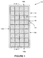
- a photovoltaic system 10 comprises a casing 12 having mounted therein a plurality of solar cells 14.
- the casing has a front 16 and opposite thereto, a rear 18 and unless the casing is parabola-shaped or has a triangularly shaped cross-section, sides 18b, 18c, 18d, 18e. These sides are preferably short so that the casing is preferably shallow.
- the system 10 includes one or several casing 12, such as described above, only one being shown for sake of clarity.
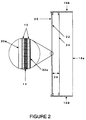
- the front of the casing is provided with a light-transmitting panel 20, (better shown at Figure 2) generally sealed to a receiving front of the solar cells 14, for transmitting solar light to the solar cells 14. Opposed to the receiving front, the solar cells have a back.
- this panel 20, on its outer side 20a, has small friction resistance or coefficient of friction.
- the rear of the casing 18 is a double wall.
- the double wall consists in a first wall 22 and a second wall 24, better shown in Figure 2.
- the first wall 22 defines, or preferably is in contact with, the back of the solar cells to enable heat transfer.
- This first wall on its side 22a away from said solar cells is of an opaque, dark-coloured, heat-absorbing surface, preferably black.
- the second wall 24 is a light-transmitting enclosure of said dark-coloured side of said first wall 22, but spaced therefrom as to produce a greenhouse effect, whereby reflected solar rays from the surroundings of the photovoltaic system are received by said rear of said casing on said dark-coloured side and said light-transmitting enclosure at said rear produces a greenhouse effect increasing the temperature of the cells and thereby of said light-transmitting panel of said front.
- the rear of the casing thus becomes a solar thermal collector at low cost.
- This light-transmitting enclosure also reduces heat loss due to winds and generally encountered around the photovoltaic system.
- the solar cells are mutually connected in a continuous plane with no spacing in between them, as shown in Figure 1 for instance.
- the light-transmitting panel 20, for transmitting solar light to the solar cells 14 of the front casing is sealed to the solar cells 14 with a polymer, preferably EVA, (polyethylene-vinylacetate), fused between said glass and said cells, as is well known in the art.
- a polymer preferably EVA, (polyethylene-vinylacetate)
- the cells are encapsulated in a polymer 15, EVA for instance, and the light-transmitting panel 20 sealed to the receiving front of the solar cells.
- light-transmitting materials may be used, if desired, bearing in mind that a waterproof and humidity proof barrier are normally provided for a good and extended life-time durability of the cells and that the light-transmitting material is subject to ultra-violet radiations, temperature variations, and that on its outer side the partition has preferably small friction resistance. Although snow accumulation is reduced even with high friction resistance.
- the outer side 22a of the casing 18 is of an opaque, dark-colour surface such as black painted or anodized metallic or polymeric surface.
- an opaque, dark-colour surface such as black painted or anodized metallic or polymeric surface.
- a black anodized or oxidized metallic foil such as those sold under the trade-mark:"Solar-L-foilTM"
- a self-adhesive black metallic foil or black paints such as those sold under the trade-mark:"Black velvetTM.
- Other opaque, dark colours may be used, though less preferred.
- a pigment inert to and mixed with, a substrate making the back of the cells might be used though less preferred.
- said outer side of an opaque, dark-coloured, solar-light absorbing surface has a low infra-red emissivity.
- the light-transmitting enclosure 24 mounted over the outer side of the rear, but spaced therefrom as shown at 26, may be a rigid or flexible plastic film being resistant to ultra-violet light.
- a LexanTM polymer a trade mark for a polycarbonate; other polycarbonates may also be used; a TeflonTM polymer, a trade mark for a polyfluoropolymer; a TedlarTM polymer, a trade mark for a polyvinylfluoride.
- Other light-transmitting enclosures nay be used, if desired, bearing in mind that the light-transmitting enclosures are subject to ultra-violet radiations, temperature variations and wind.
- the light-transmitting enclosure is preferably spaced from the outer side having an opaque, dark-colour of a distance of 0.1 to 5 cm and more preferably from 0.5 to 2 cm.
- the temperature of the photovoltaic systems provided with the outer side having an opaque, dark-coloured surface and the light-transmitting enclosure is about 20°C higher than that of conventional systems.
- This elevation in temperature increasing the temperature of the cells and thereby,when said light-transmitting panel of said front for transmitting solar light to said solar cells is at or above the melting temperature of water, said panel causing any snow, frost and ice present on said panel to form a water film on which any remaining snow, frost and ice slide down, and when said light-transmitting panel of said front is below the melting temperature of water, said panel which has a temperature higher than ambient temperature, causing accelerated sublimation of any snow, frost and ice present in frozen form on said panel.
- the performances are even more interesting when one considers that the accumulated snow in front of the light-transmitting panel of said front for transmitting solar light, is a thermal insulation between the heated surface of the light-transmitting panel and ambient air. This enables a quicker raising of the temperature of the light-transmitting panel.
- the solar cells are operating under constant voltage and the dimensions of the photovoltaic systems are set for the fall season and are thereby oversized for summer months.
- the light-transmitting panel is at an angle with the horizontal and preferably said angle with the horizon is the angle of the latitude at which said system is operating plus 15°.
- this system may be made brand-new, or by providing the walls 22, 24 as described above, it may be added to a new module in the factory or retrofit on installed conventional photovoltaic systems.
- Example A was a conventional module having only a first wall, such as 22, white, while the other (Example 1) was a module having a double wall, with a wall, such as 22, black.
- Example 1 After a snow fall leaving 2 cm, within 3 hours of bright sunshine the next sunny day at an ambient temperature of -15°C, in Example 1, the snow melted and cleared out over the light-transmitting panel. After two days, the snow had but partially left the light-transmitting panel of Sample A. In Example 1, the temperature of the module had risen above 0°C, while in Sample A, the measured temperature was about -5°C.
Landscapes
- Photovoltaic Devices (AREA)
Applications Claiming Priority (2)
| Application Number | Priority Date | Filing Date | Title |
|---|---|---|---|
| US08/091,047 US5368654A (en) | 1993-07-14 | 1993-07-14 | Photovoltaic system using reflected solar rays of the surroundings and method therefor, to dispose of snow, frost and ice |
| US91047 | 2002-03-04 |
Publications (2)
| Publication Number | Publication Date |
|---|---|
| EP0634801A2 true EP0634801A2 (de) | 1995-01-18 |
| EP0634801A3 EP0634801A3 (de) | 1998-01-14 |
Family
ID=22225652
Family Applications (1)
| Application Number | Title | Priority Date | Filing Date |
|---|---|---|---|
| EP94201961A Withdrawn EP0634801A3 (de) | 1993-07-14 | 1994-07-07 | Photovoltaische Anordnung, die reflektierte Sonnenstrahlen aus der Umgebung benützt, und Methode zur Beseitigung von Schnee, Frost und Eis |
Country Status (3)
| Country | Link |
|---|---|
| US (1) | US5368654A (de) |
| EP (1) | EP0634801A3 (de) |
| CA (1) | CA2123752C (de) |
Families Citing this family (19)
| Publication number | Priority date | Publication date | Assignee | Title |
|---|---|---|---|---|
| US6005184A (en) * | 1997-07-11 | 1999-12-21 | Space Systems/Loral, Inc. | Solar panels having improved heat dissipation properties |
| US5972732A (en) * | 1997-12-19 | 1999-10-26 | Sandia Corporation | Method of monolithic module assembly |
| US6118067A (en) * | 1998-11-20 | 2000-09-12 | Swales Aerospace | Method and apparatus for improved solar concentration arrays |
| US6458322B1 (en) * | 2000-09-08 | 2002-10-01 | Bioavailability Systems, Llc | Method for simplified shipping of clinical specimens and optional direct analysis |
| US20090194156A1 (en) * | 2008-02-01 | 2009-08-06 | Grommesh Robert C | Dual seal photovoltaic glazing assembly and method |
| US20090320921A1 (en) * | 2008-02-01 | 2009-12-31 | Grommesh Robert C | Photovoltaic Glazing Assembly and Method |
| US20090194147A1 (en) * | 2008-02-01 | 2009-08-06 | Cardinal Ig Company | Dual seal photovoltaic assembly and method |
| WO2009126186A1 (en) * | 2008-04-10 | 2009-10-15 | Cardinal Ig Company | Manufacturing of photovoltaic subassemblies |
| CA2720257A1 (en) * | 2008-04-10 | 2009-10-15 | Cardinal Ig Company | Glazing assemblies that incorporate photovoltaic elements and related methods of manufacture |
| US20100236608A1 (en) * | 2009-03-20 | 2010-09-23 | Ball Jasper T | Photovoltaic module with heater |
| US20110056924A1 (en) * | 2009-09-10 | 2011-03-10 | Benjamin Park Townsend | Solar defrost panels |
| CN101693440B (zh) * | 2009-09-22 | 2011-04-13 | 无锡市新区梅村镇同春太阳能光伏农业种植园 | 铜铟镓硒薄膜太阳能电池应用在公交车门上的保暖装置 |
| US8440940B2 (en) * | 2010-03-26 | 2013-05-14 | Richard Backe | Photovoltaic ice dam remediation apparatus |
| US10292208B2 (en) | 2011-07-12 | 2019-05-14 | Montgomery W. Childs | Solar panel |
| US10014822B2 (en) | 2016-01-04 | 2018-07-03 | Tariq Sikander | Snow removal assembly |
| CN108075354A (zh) | 2016-11-14 | 2018-05-25 | 中国科学院苏州纳米技术与纳米仿生研究所 | 窄线宽激光器 |
| WO2020220005A1 (en) | 2019-04-26 | 2020-10-29 | Van Straten Enterprises, Inc. | Heater and electromagnetic illuminator heater |
| US12121088B2 (en) | 2021-01-21 | 2024-10-22 | Van Straten Enterprises, Inc. | Optical face protection shield, heated optical face protection apparatus, and method |
| US11716053B1 (en) | 2022-06-05 | 2023-08-01 | Joel D. Martin, LLC | Solar panel snow melter |
Family Cites Families (23)
| Publication number | Priority date | Publication date | Assignee | Title |
|---|---|---|---|---|
| JPS5372487A (en) * | 1976-12-08 | 1978-06-27 | Sharp Corp | Solar cell unit |
| DE2814243A1 (de) * | 1978-04-03 | 1979-10-11 | Resol Elektronische Regelungen | Elektronische regelung fuer mehrspeicher-sonnenheizsysteme |
| DE2936764C2 (de) * | 1979-09-12 | 1984-05-17 | Klaus Dipl.-Ing. 6101 Fränkisch-Crumbach Hänsel | Terrestrischer Solargenerator |
| JPS5673478A (en) * | 1979-11-20 | 1981-06-18 | Fujitsu Ltd | Structure for panel surface of solar cell |
| JPS5678176A (en) * | 1979-11-29 | 1981-06-26 | Fujitsu Ltd | Solar battery panel system |
| ES493803A0 (es) * | 1980-07-29 | 1981-05-16 | Cuevas Fernandez Andres | Paneles de celulas bifaciales para luz directa y albedo |
| JPS5922369A (ja) * | 1982-07-29 | 1984-02-04 | Fujitsu Ltd | 太陽光による発電装置の防雪方法 |
| JPS5922370A (ja) * | 1982-07-29 | 1984-02-04 | Fujitsu Ltd | 太陽光による発電装置の除雪機構 |
| JPS5934671A (ja) * | 1982-08-20 | 1984-02-25 | Fujitsu Ltd | 太陽光による発電装置の防雪構造 |
| JPS5934670A (ja) * | 1982-08-20 | 1984-02-25 | Fujitsu Ltd | 太陽光による発電装置の防雪方法 |
| JPS5934669A (ja) * | 1982-08-20 | 1984-02-25 | Fujitsu Ltd | 太陽光による発電装置の防雪方式 |
| JPS5941873A (ja) * | 1982-09-01 | 1984-03-08 | Fujitsu Ltd | 太陽光による発電装置の着雪防止構造 |
| JPS59231877A (ja) * | 1983-06-13 | 1984-12-26 | Fujitsu Ltd | 太陽電池の着雪防止装置 |
| JPS60138980A (ja) * | 1983-12-27 | 1985-07-23 | Agency Of Ind Science & Technol | 太陽電池パネル設置方式 |
| JPS60235442A (ja) * | 1984-05-08 | 1985-11-22 | Sanyo Electric Co Ltd | 光起電力連係制御装置 |
| JPS6199384A (ja) * | 1984-10-22 | 1986-05-17 | Toshiba Corp | 太陽電池アレイ保護装置 |
| JPS6218074A (ja) * | 1985-07-16 | 1987-01-27 | Fujitsu Ltd | 太陽電池の除雪方式 |
| JPS62122181A (ja) * | 1985-11-21 | 1987-06-03 | Toshiba Corp | 太陽電池モジユ−ル |
| JPS62285477A (ja) * | 1986-06-02 | 1987-12-11 | Sumitomo Electric Ind Ltd | 太陽電池の設置方法 |
| JPS6316681A (ja) * | 1986-07-08 | 1988-01-23 | Mitsubishi Electric Corp | 光発電装置 |
| JPH01178691A (ja) * | 1988-01-07 | 1989-07-14 | Fujisash Co | 結露防止建具 |
| DE3903521C2 (de) * | 1989-02-07 | 1993-11-25 | Kunert Heinz | Transparentes Element zur Verwendung als Fenster-, Wand, Dach- oder Brüstungselement |
| JPH0579137A (ja) * | 1991-09-25 | 1993-03-30 | Mitsubishi Electric Corp | 太陽光発電装置 |
-
1993
- 1993-07-14 US US08/091,047 patent/US5368654A/en not_active Expired - Lifetime
-
1994
- 1994-05-17 CA CA002123752A patent/CA2123752C/en not_active Expired - Fee Related
- 1994-07-07 EP EP94201961A patent/EP0634801A3/de not_active Withdrawn
Also Published As
| Publication number | Publication date |
|---|---|
| CA2123752A1 (en) | 1995-01-15 |
| US5368654A (en) | 1994-11-29 |
| EP0634801A3 (de) | 1998-01-14 |
| CA2123752C (en) | 1999-02-16 |
Similar Documents
| Publication | Publication Date | Title |
|---|---|---|
| US5368654A (en) | Photovoltaic system using reflected solar rays of the surroundings and method therefor, to dispose of snow, frost and ice | |
| WO2010107491A2 (en) | Photovoltaic module with heater | |
| US20140338730A1 (en) | Photovoltaic module with heater | |
| US20070056579A1 (en) | Energy Channeling Sun Shade System and Apparatus | |
| KR100980688B1 (ko) | 발전과 차양을 겸하는 건축물 일체형 태양광 발전장치 | |
| CN101227158A (zh) | 自动追踪式太阳能发电机 | |
| KR101378405B1 (ko) | 태양광발전을 이용한 주차관제 장치 | |
| JP2009510291A (ja) | 光電池屋根棟キャップおよび設置方法 | |
| US20110209743A1 (en) | Photovoltaic cell apparatus | |
| KR100796245B1 (ko) | 건물일체형 태양광발전 시스템 전용 고효율 전동 이중창 | |
| EP4356512A1 (de) | Elektrische solarvorrichtung und system für architektonische verwendungen | |
| US20040134482A1 (en) | Isolation shield system, insolation shield and method | |
| KR100930599B1 (ko) | 태양전지판의 자연 청소를 위한 태양전지판 구동 제어방법 | |
| CN215530311U (zh) | 一种光伏玻璃温室 | |
| CN117836675A (zh) | 棱柱式太阳能聚光器 | |
| KR200483807Y1 (ko) | 디스플레이장치가 구비된 커튼월 | |
| KR20190143093A (ko) | 태양광 발전 차양 | |
| KR101159195B1 (ko) | 염료감응 태양전지를 이용한 노면 결빙 방지장치 | |
| CN202359967U (zh) | 太阳能板和包括其的结构元件 | |
| KR20090113797A (ko) | 일사량 변화에 따른 태양광 발전장치 및 그 방법 | |
| KR20250074477A (ko) | 유리 온실 | |
| CN214177216U (zh) | 铺装式平面太阳能瓦装置 | |
| RU216726U1 (ru) | Уличный фонарь с цилиндрической солнечной панелью | |
| US20250247041A1 (en) | Building-integrated thermal photovoltaic building cladding system | |
| US20260039244A1 (en) | Energy conversion apparatus capable of automatic light compensation and light recycling |
Legal Events
| Date | Code | Title | Description |
|---|---|---|---|
| PUAI | Public reference made under article 153(3) epc to a published international application that has entered the european phase |
Free format text: ORIGINAL CODE: 0009012 |
|
| AK | Designated contracting states |
Kind code of ref document: A2 Designated state(s): AT CH DE FR IT LI |
|
| PUAL | Search report despatched |
Free format text: ORIGINAL CODE: 0009013 |
|
| AK | Designated contracting states |
Kind code of ref document: A3 Designated state(s): AT CH DE FR IT LI |
|
| STAA | Information on the status of an ep patent application or granted ep patent |
Free format text: STATUS: THE APPLICATION IS DEEMED TO BE WITHDRAWN |
|
| 18D | Application deemed to be withdrawn |
Effective date: 19980203 |