EP0634733B1 - Bildverarbeitung - Google Patents
Bildverarbeitung Download PDFInfo
- Publication number
- EP0634733B1 EP0634733B1 EP94201977A EP94201977A EP0634733B1 EP 0634733 B1 EP0634733 B1 EP 0634733B1 EP 94201977 A EP94201977 A EP 94201977A EP 94201977 A EP94201977 A EP 94201977A EP 0634733 B1 EP0634733 B1 EP 0634733B1
- Authority
- EP
- European Patent Office
- Prior art keywords
- image
- pixel
- values
- pixels
- depth values
- Prior art date
- Legal status (The legal status is an assumption and is not a legal conclusion. Google has not performed a legal analysis and makes no representation as to the accuracy of the status listed.)
- Expired - Lifetime
Links
Images


Classifications
-
- G—PHYSICS
- G06—COMPUTING OR CALCULATING; COUNTING
- G06T—IMAGE DATA PROCESSING OR GENERATION, IN GENERAL
- G06T3/00—Geometric image transformations in the plane of the image
-
- G—PHYSICS
- G06—COMPUTING OR CALCULATING; COUNTING
- G06T—IMAGE DATA PROCESSING OR GENERATION, IN GENERAL
- G06T13/00—Animation
-
- G—PHYSICS
- G06—COMPUTING OR CALCULATING; COUNTING
- G06T—IMAGE DATA PROCESSING OR GENERATION, IN GENERAL
- G06T15/00—Three-dimensional [3D] image rendering
- G06T15/10—Geometric effects
- G06T15/40—Hidden part removal
-
- G—PHYSICS
- G06—COMPUTING OR CALCULATING; COUNTING
- G06T—IMAGE DATA PROCESSING OR GENERATION, IN GENERAL
- G06T15/00—Three-dimensional [3D] image rendering
- G06T15/10—Geometric effects
- G06T15/40—Hidden part removal
- G06T15/405—Hidden part removal using Z-buffer
-
- H—ELECTRICITY
- H04—ELECTRIC COMMUNICATION TECHNIQUE
- H04N—PICTORIAL COMMUNICATION, e.g. TELEVISION
- H04N5/00—Details of television systems
- H04N5/44—Receiver circuitry for the reception of television signals according to analogue transmission standards
- H04N5/445—Receiver circuitry for the reception of television signals according to analogue transmission standards for displaying additional information
- H04N5/45—Picture in picture, e.g. displaying simultaneously another television channel in a region of the screen
-
- A—HUMAN NECESSITIES
- A63—SPORTS; GAMES; AMUSEMENTS
- A63F—CARD, BOARD, OR ROULETTE GAMES; INDOOR GAMES USING SMALL MOVING PLAYING BODIES; VIDEO GAMES; GAMES NOT OTHERWISE PROVIDED FOR
- A63F2300/00—Features of games using an electronically generated display having two or more dimensions, e.g. on a television screen, showing representations related to the game
- A63F2300/20—Features of games using an electronically generated display having two or more dimensions, e.g. on a television screen, showing representations related to the game characterised by details of the game platform
- A63F2300/203—Image generating hardware
-
- A—HUMAN NECESSITIES
- A63—SPORTS; GAMES; AMUSEMENTS
- A63F—CARD, BOARD, OR ROULETTE GAMES; INDOOR GAMES USING SMALL MOVING PLAYING BODIES; VIDEO GAMES; GAMES NOT OTHERWISE PROVIDED FOR
- A63F2300/00—Features of games using an electronically generated display having two or more dimensions, e.g. on a television screen, showing representations related to the game
- A63F2300/60—Methods for processing data by generating or executing the game program
- A63F2300/64—Methods for processing data by generating or executing the game program for computing dynamical parameters of game objects, e.g. motion determination or computation of frictional forces for a virtual car
- A63F2300/643—Methods for processing data by generating or executing the game program for computing dynamical parameters of game objects, e.g. motion determination or computation of frictional forces for a virtual car by determining the impact between objects, e.g. collision detection
-
- A—HUMAN NECESSITIES
- A63—SPORTS; GAMES; AMUSEMENTS
- A63F—CARD, BOARD, OR ROULETTE GAMES; INDOOR GAMES USING SMALL MOVING PLAYING BODIES; VIDEO GAMES; GAMES NOT OTHERWISE PROVIDED FOR
- A63F2300/00—Features of games using an electronically generated display having two or more dimensions, e.g. on a television screen, showing representations related to the game
- A63F2300/60—Methods for processing data by generating or executing the game program
- A63F2300/66—Methods for processing data by generating or executing the game program for rendering three dimensional images
Definitions
- the present invention relates to a method of image processing and image processing apparatus.
- the present invention relates to a method of image processing in which moving output images are presented as a two dimensional display, in the form of time-separated two-dimensional frames of picture elements (pixels), wherein said output images are constructed from a first image and from a second image and, over a plurality of frames, said first image appears to move relative to a second image.
- moving output images are presented as a two dimensional display, in the form of time-separated two-dimensional frames of picture elements (pixels), wherein said output images are constructed from a first image and from a second image and, over a plurality of frames, said first image appears to move relative to a second image.
- a problem which the present invention seeks to overcome is to provide an environment which moves towards combining the interactivity of computer graphics with the image quality of video graphics.
- each of said first and second images has absolute depth values defined for substantially all of the pixels making up the respective images
- the present invention also provides image processing apparatus apparatus, including means for presenting moving output images to a two-dimensional display, in the form of time separated two-dimensional frames of pixels, and means for constructing said output images from a first image and from a second image such that over a plurality of frames, said first image appears to move relative to said second image which is characterised by:
- an advantage of the present invention is that it provides an environment for three dimensional interactivity, while processing images on a pixel-by-pixel basis, so as to facilitate good picture quality.
- the depth values are compressed, prior to being stored with the video information and de-compressed during playback.
- Compression may be effected by a process of quantisation and two-dimensional run length encoding, and compression may be in accordance with the MPEG standard.
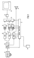
- FIG. 1 A system for reading video sequences from an optical compact disc is shown in Figure 1.
- the system is arranged to combine three video planes, in which pixel values for each plane contain depth and opacity values, in addition to two-dimensional data and colour data.
- Data representing video images, audio signals and control programs, are stored on conventional optical compact discs.
- the data on said discs is read by a disc player 15 and supplied as a serial bit stream to a controller 16, at a rate of one hundred and fifty kilobytes per second.
- the controller 16 is arranged to identify the nature of the data being supplied thereto and to direct said data to the appropriate processing circuitry. Thus, control programs are supplied to a control processor 17, audio signals are supplied to an audio processor 18 and video signals are supplied to a first random access memory device 19 or to a second random access memory device 20.
- Memory devices 19 and 20 are arranged to receive video signals encoded under different standards.
- device 19 is arranged to receive substantially uncompressed video data, for the generation of small moving objects or still frames, while memory device 20 is arranged to receive video data compressed in accordance with the standard proposed by the ISO Moving Picture Experts Group (MPEG).
- MPEG Moving Picture Experts Group
- memory device 19 may also be arranged to receive compressed video data.
- memory device 19 receives data relating to two video planes, commonly referred to an "A" plane and a "B" plane. Each of these planes has a respective video processor 21 or 22, arranged to supply video signals V1 and V2 to a video mixer 23. Similarly, a video processor 24 receives MPEG encoded video data from random access memory device 20, decodes said data and again supplies a video signal V3 to the mixer 23.
- the mixer 23 is arranged to combine the video signals, V1, V2 and V3, supplied thereto, to provide a digital video output signal to a digital to analog converter 25, which in turn supplies a conventional video signal to a video monitor or television set 26.
- audio signals from the audio processor 18 are supplied to a loudspeaker 27, or combined with the output from the digital to analog converter 25, possibly modulated thereafter and supplied to a suitable input of a television set.
- initial information supplied from an optical disc would include programs for the control processor 17, which would then configure the system to suitably process further information, in the form of video and audio, from said player 15.
- control of the system is also effected by an operator controlled interactive input, received from a hand controller 28.
- the video images produced by video processors 21 and 22 represent foreground items, which may be considered as being similar to actors performing on a stage.
- said objects are also configured to move and appear to move in the Z dimension, that is to say, in a direction perpendicular to the plane of the image.
- the video image produced by the video processor 24 effectively represents a background, this being a full video frame capable of producing images at full video rate.
- the perceived movement of the foreground images is enhanced by them being seen to go behind elements of the background image, produced by processor 24, as their Z dimension increases, that is to say, as they move further away from the front plane of the displayed image.
- the background image produced by processor 24 may be considered as representing scenery, in which some portions of said scenery have a different Z dimension to other portions of said scenery.
- the first image will appear to move further away from or nearer to the display plane, so as to be in front of or behind elements of the second image, in response to depth values defined by the first image.
- the second image also has depth values, defined for each pixel of said image.
- depth values of the first image are compared with depth values of the pixels of the second image to determine, on a pixel-by-pixel basis, whether the first image is in front of or behind the pixels of said second image.
- the mixer 23 is arranged to produce an output image generated predominantly from contributions from the front-most pixels of either the first image or the second image.
- each pixel generated by the video processor 24 also has a multi-bit value identifying the opacity of that particular pixel.
- a pixel when fully opaque and when in the position of being the front-most pixel, a pixel will totally obscure any pixels found in lower planes. Similarly, when totally transparent, the pixel is not seen and image data is obtained from underlying pixels.
- intermediate values may be given to the opacity values, resulting in a degree of blending between an upper and a lower pixel.
- the inclusion of these opacity values at the edges of objects provides image blending.
- objects from different planes overlap they are given soft anti-aliased edges so as to achieve a natural looking result.
- the mixer 23 It is necessary for the mixer 23 to consider depth, opacity and colour for each pixel of the three input video planes, in order to produce an output signal which is supplied to the digital to analog converter 25. This is achieved by supplying depth values associated with each of the video signals to a depth resolving circuit. This depth resolving circuit produces a relative depth, or order, value for each pixel of the three planes and these depth values are in turn supplied to an opacity calculation circuit, for producing image factors for each of the three planes. Thus, blending on a pixel-by-pixel basis is performed with reference to the relative depth of the pixels and the pixel opacity.
- the depth resolving circuit forming part of the mixer 23, is detailed in Figure 2.
- a four bit depth value is available for each pixel and said four bit values DV1, DV2, DV3 are supplied as inputs to respective look up tables 31, 32, 33.
- each look-up table consists of sixteen addressable entries and each of said addressable entries comprises a total of six bits.
- the look up tables are programmable, via a data-bus 34, therefore the conversion of the four bit input values to six bit values may be changed, on a frame-by-frame basis if so desired.
- the depth resolution produced by the system is significantly greater than that provided by the initial four bits generated on a pixel-by-pixel basis.
- Each six bit value is supplied to each of three comparators 35, 36, 37, each of which may produce an output signal on a line 38, indicating that one of the inputs supplied thereto is in front of one of the other inputs supplied thereto or, alternatively, they may produce an output on a line 39, indicating that the levels are equal.
- the output signals on line 38 are supplied to a look up table 40 which, from said three input values, produces depth ordering values, each of two bits.
- a first output line 41 identifies the relative position of video plane V3, that is to say, a two bit value is generated identifying this plane as being at the front, in the middle or at the back.
- a two bit value is generated to identify the position of video plane V2 and a similar two bit value is generated on line 43 to identify the position of video plan V1.
- an ordering is produced on a pixel-by-pixel basis for each of the video planes.
- the outputs from look up tables 31, 32 and 33 represent actual positions in the Z direction
- the outputs from look up table 40 merely represent an ordering preference, that is to say, the two-bit values identify obscuration priorities for the three video planes.
- the outputs from line 39 may be used to indicate that a collision has occurred, particularly useful in video games etc., and the existence of such a collision is logged in a collision logging circuit 44, which in turn supplies data back to the control processor 17 via the data-bus 34.
- the circuit shown in Figure 2 automatically tracks the movement of objects in the depth direction. Thus this function does not have to be provided by an application program. Similarly, the provision of circuit 44 identifies data to the application program to the effect that a collision has occurred, again, removing another burden from the requirements of the application program.
- FIG. 3 An opacity calculation circuit is shown in Figure 3, in which four bit opacity values OV1, OV2, OV3 for each of the three video planes are supplied to respective look up tables 51, 52, 53.
- the look up tables 51, 52, 53 are each eight bits deep and the actual way in which the four bit input values are converted into eight bit output values may be controlled on a frame by frame basis, in response to data supplied from the control processor 17.
- the number of bits provided for both the depth values and the opacity values are expanded by means of look up tables.
- the expansion of depth values allows for more than sixteen object depths to be provided. Furthermore, it also allows the depth of an object to be changed by changing its depth look up table, without changing the actual coded data for the object.
- the expansion of opacity values to eight bits, from an initial four bits, allows soft fading to be provided between images.
- look up table values may be changed on a frame-by-frame basis, possibly giving a first position on the first frame and an intermediate position on a second frame, from the same input data, in order to provide the soft edge.
- a summation circuit 54, a summation circuit 55, a multiplier 56 and a second multiplier 57 are configured in such a way as to receive pixel values from the first, second and third planes, re-ordered as front, middle and back, as defined by the two-bit position codes from table 40.
- the re-ordering of these planes is achieved by means of multiplexers 58, 59, 60, each arranged to receive the three outputs from the look up tables 51, 52, 53 and to select an output in response to said two bit values.
- the output from each multiplexer may be equivalent to any one of the outputs from the three look up tables 51, 52 and 53.
- multiplexers 61, 62 and 63 receive the ordering information, suitably modified by a look up table 64.
- the output from multiplexer 61 consists of an image factor IF(V1) for the first video image
- the output from multiplexer 62 consists of an image factor IF(V2) for the second video image
- the output from a multiplexer 63 consists of an image factor IF(V3) for the third video image.
- the image factor data takes account of pixel position in the Z dimension and also takes account of pixel opacity. In this way, the video images may be combined by simple addition, their position and opacity values being taken into account by their respective image factors.
- An image factor for the front video image is generated by the multiplexer 58 and supplied to each of the multiplexers 61, 62 and 63.
- Summation circuit 54 receives a fixed value of 255 at its positive input and receives the output from multiplexer 58 at its negative input.
- the output from summation circuit 54 consists of the front image factor subtracted from 255, which is in turn supplied to multiplier 56.
- the middle image factor is generated as the output from multiplier 56, which receives the output from multiplexer 59 at its second input.
- the output from multiplexer 58 is also supplied to a negative input of summation circuit 55, which also receives the output from multiplier 56 at a negative input. Thus, these two inputs are subtracted from a fixed value of 255, which is in turn supplied to an input of a multiplier 57.
- Multiplier 57 receives at its second input the output from multiplexer 60, to generate the back image factor for each of the three output multiplexers 61, 62 and 63.
- the first video image is notionally the front video image
- the second video image is notionally the middle video image
- the third video image is notionally the back video image.
- these orders may be adjusted on a pixel-by-pixel basis.
- the circuit shown in Figure 3 takes account of this information and, in addition, introduces blending information to produce image factor information for each of the three video signals.
- the image factor information generated by the circuit shown in Figure 3 is supplied to a video combining circuit, in addition to the actual video information for each of the planes.
- each video signal consists of eight bits allocated to each of the red, green and blue colour components, although matrix circuitry may have been included to convert alternatively coded video information, such as luminance plus colour difference values, into suitably encoded additive red, green and blue signals.
- Each video signal V1, V2, V3 is supplied to a collection of three multipliers 71, 72, 73, each arranged to multiply one of the colour components by the respective image factor. All of the processed red components are then combined in a red summation circuit 64, with all the processed green components combined in a similar summation circuit 65 and the processed blue components combined in a similar summation circuit 66. The output from each summation circuit 64, 65, 66 provides one of the colour signals, via a suitable limiting circuit 67.
- the depth information and the opacity information both consist of four bits for each pixel location, thereby increasing the amount of data required for each pixel by a further eight bits.
- a depth value is identified for each pixel of the frame.
- the depth values are effectively defined to a resolution of six bits and a quantisation matrix is selected for the image frame.
- a best match is identified for converting these six bit values to four bit values, from the available quantisation matrices.
- the six bit values are quantised to four bits, using the selected quantisation matrix and data identifying the selected matrix is stored, allowing it to be used for the programming of look up tables 31, 32 and 33 of Figure 2.
- Edges of objects within the frame are effectively tracked. Two consecutive lines of data are considered, in which the first line has been coded, with a view to coding the second line. Positions at which transitions occur are recorded for the first line and on considering the second line, the positions of transitions in the second line are considered and an attempt is made, effectively, to match up the transitions of the second line with similar transitions of the first line. This results in a list of changes which, given data derived from the first line, will allow the new line to be specified.
- an output code is generated to the effect that the same edge is present but at a specified horizontal offset from the corresponding edge of the previous line.
- a very common example is to the effect that the edge has actually stayed in the same position.
- the second type consists of data to the effect that there is no edge in the second line which corresponds to the edge in the first line, therefore requiring data to the effect that the edge is to be ignored.
- edge specifications are very much more common than others, therefore this inherent redundancy facilitates the use of Huffman coding, thereby providing further compression.
- Huffman coding thereby providing further compression.
- the situation in which an edge is repeated in the next position may be coded as a single bit, thereby achieving a maximum degree of compression.
- chroma-keying techniques to provide depth specifications.
- a blue pixel is processed as if it were completely transparent, allowing other objects in the frame to be placed against a new background.
- the transparent colour could be processed in such a way as to treat the pixel as being placed at the furthest distance in the Z direction, effectively placing it behind all other objects.
- the invention also encompasses an image storage and encoding method which comprises storing pixel values with associated depth values and to a storage medium, such as an optical disc, containing picture information in the form of pixel values and associated depth values.
Landscapes
- Engineering & Computer Science (AREA)
- Physics & Mathematics (AREA)
- General Physics & Mathematics (AREA)
- Theoretical Computer Science (AREA)
- Geometry (AREA)
- Computer Graphics (AREA)
- Multimedia (AREA)
- Signal Processing (AREA)
- Processing Or Creating Images (AREA)
- Image Processing (AREA)
- Image Generation (AREA)
- Studio Circuits (AREA)
Claims (12)
- Verfahren zur Bildverarbeitung, bei dem sich bewegende Ausgangsbilder als zweidimensionale Anzeige (26) dargestellt werden, und zwar in Form von zeitlich getrennten zweidimensionalen Einzelbildern mit Bildelementen (Pixeln), wobeidie genannten Ausgangsbilder aus einem ersten Bild und einem zweiten Bild zusammengesetzt werden; undwobei sich das erste genannte Bild über eine Vielzahl von Einzelbildern in Bezug auf ein zweites Bild zu bewegen scheint, dadurch gekennzeichnet, dassfür jedes der genannten ersten und zweiten Bilder absolute Tiefewerte (DV1, DV2, DV3) für alle Bildelemente definiert werden, aus denen sich die jeweiligen Bilder zusammensetzen;Tiefewerte des genannten ersten Bildes mit den Tiefewerten der Bildelemente des genannten zweiten Bildes verglichen werden, um Bildelement für Bildelement zu ermitteln, ob Bildelemente des ersten Bildes vor oder hinter den Bildelementen des genannten zweiten Bildes liegen;wobei die genannten absoluten Tiefewerte mit einer höheren Auflösung verarbeitet werden, aber mit einer geringeren Auflösung gespeichert werden, und wobei die Werte mit geringerer Auflösung mit Hilfe einer Verweistabelle (31, 32, 33) in Werte mit höherer Auflösung konvertiert werden; und dadurch, dassman bevorzugte Beiträge aus den vordersten Bildelementen von entweder dem ersten Bild oder dem zweiten Bild erhält, um ein Ausgangsbild zu erzeugen, in dem sich das genannte erste Bild in eine Anzeigeebene hinein oder aus einer Anzeigeebene heraus zu bewegen scheint, so dass es vor oder hinter Elementen des genannten zweiten Bildes liegt, und zwar in Abhängigkeit von deren relativen Tiefewerten.
- Verfahren nach Anspruch 1, wobei die genannte Verweistabelle für jedes Einzelbild umprogrammierbar ist.
- Verfahren nach Anspruch 1, wobei die Tiefewerte als eine Gruppe von Werten gespeichert werden, die durch einen Prozeß der zweidimensionalen Lauflängen-Codierung komprimiert wurden und mit zeitlich und räumlich komprimierten Videodaten kombiniert wurden.
- Verfahren nach Anspruch 3, wobei Opazitätswerte für jedes Bildelement des genannten ersten und des genannten zweiten Bildes geliefert werden und mit den genannten Tiefewerten verarbeitet werden, um einen Bildfaktor für jedes Bildelement jedes Bildes zu berechnen.
- Verfahren nach Anspruch 1, mit einem dritten Videobild, wobei Tiefewerte Bildelement für Bildelement für jede entsprechende Bildelementposition für jedes der drei genannten Bilder betrachtet werden.
- Bildverarbeitungsvorrichtung mit Mitteln zum Darstellen von sich bewegenden Ausgangsbildern auf einer zweidimensionalen Anzeige (26) in Form von zeitlich getrennten zweidimensionalen Einzelbildern aus Bildelementen, und mit Mitteln zum Konstruieren der genannten Ausgangsbilder ausgehend von einem ersten Bild und von einem zweiten Bild auf eine solche Weise, dass sich das genannte erste Bild über eine Vielzahl von Einzelbildern relativ zu dem genannten zweiten Bild zu bewegen scheint, gekennzeichnet durch:Mittel (21, 22, 24) zum Verarbeiten der genannten Daten mit einer höheren Auflösung, so dass das genannte erste Bild sich in ein Anzeige-Einzelbild hinein oder aus einem Anzeige-Einzelbild heraus zu bewegen scheint, so dass es vor oder hinter Elementen des genannten zweiten Bildes liegt, und zwar in Abhängigkeit von den für das genannte erste Bild definierten Tiefewerten, wobei für das genannte erste Bild und das genannte zweite Bild absolute Tiefewerte für alle Bildelemente definiert sind, aus denen sich die jeweiligen Bilder zusammensetzen;Mittel zum Empfangen der mit einer geringeren Auflösung gespeicherten Tiefewerte (DV1, DV2, DV3), die dazu dienen, diese mit Hilfe von Verweistabellen (31, 32, 33) in die genannten Werte mit höherer Auflösung zu konvertieren;Mittel (35, 36, 37) zum Vergleichen der Tiefewerte des genannten ersten Bildes mit den Tiefewerten von Bildelementen des genannten zweiten Bildes, um Bildelement für Bildelement zu ermitteln, ob Bildelemente des genannten ersten Bildes vor oder hinter Bildelementen des genannten zweiten Bildes liegen; undMittel (23) zum Kombinieren der bevorzugten Beiträge von den vordersten Bildelementen von entweder dem ersten Bild oder dem zweiten Bild, um ein Ausgangsbild zu erzeugen.
- Vorrichtung nach Anspruch 6, mit Mitteln zum Umprogrammieren der genannten Verweistabellen auf Einzelbildbasis.
- Vorrichtung nach Anspruch 6, mit Mitteln zum Entkomprimieren von zweidimensionalen lauflängen-codierten Daten, die die genannten Tiefewerte definieren.
- Vorrichtung nach Anspruch 6, mit Mitteln zum Liefern von Opazitätswerten für jedes Bildelement der Videobilder, und mit
Verarbeitungsmitteln zum Verarbeiten der genannten Opazitätswerte, um Bildfaktoren für jedes Bildelement jedes Eingangsbildes zu berechnen. - Vorrichtung nach Anspruch 9, mit Mitteln zum Entkomprimieren und Decodieren von Opazitätswerten, die durch Quantisierung und zweidimensionale Lauflängen-Codierung codiert wurden und von einem Speichergerät gelesen wurden.
- Vorrichtung nach Anspruch 9, wobei die genannten Opazitätswerte aus Daten erzeugt werden, die die Position der Kantenübergänge mit einer Auflösung definieren, die größer ist als der Abstand der Bildelemente.
- Vorrichtung nach Anspruch 6, mit Mitteln zum Erzeugen eines dritten Videobildes, wobei Tiefewerte Bildelement für Bildelement für jede Bildelementposition für jedes der genannten drei Bilder betrachtet werden.
Applications Claiming Priority (2)
| Application Number | Priority Date | Filing Date | Title |
|---|---|---|---|
| GB9314717 | 1993-07-15 | ||
| GB939314717A GB9314717D0 (en) | 1993-07-15 | 1993-07-15 | Image processing |
Publications (3)
| Publication Number | Publication Date |
|---|---|
| EP0634733A2 EP0634733A2 (de) | 1995-01-18 |
| EP0634733A3 EP0634733A3 (de) | 1995-07-12 |
| EP0634733B1 true EP0634733B1 (de) | 1999-12-08 |
Family
ID=10738914
Family Applications (1)
| Application Number | Title | Priority Date | Filing Date |
|---|---|---|---|
| EP94201977A Expired - Lifetime EP0634733B1 (de) | 1993-07-15 | 1994-07-08 | Bildverarbeitung |
Country Status (6)
| Country | Link |
|---|---|
| US (1) | US5784064A (de) |
| EP (1) | EP0634733B1 (de) |
| JP (1) | JP3645922B2 (de) |
| KR (1) | KR100329874B1 (de) |
| DE (1) | DE69421967T2 (de) |
| GB (1) | GB9314717D0 (de) |
Families Citing this family (17)
| Publication number | Priority date | Publication date | Assignee | Title |
|---|---|---|---|---|
| GB9613039D0 (en) * | 1996-06-21 | 1996-08-28 | Philips Electronics Nv | Image data compression for interactive applications |
| US6128021A (en) * | 1996-10-01 | 2000-10-03 | Philips Electronics North America Corporation | Downloading image graphics with accelerated text character and line art creation |
| JPH10145583A (ja) * | 1996-11-14 | 1998-05-29 | Casio Comput Co Ltd | 画像処理装置 |
| US6262694B1 (en) * | 1997-03-11 | 2001-07-17 | Fujitsu Limited | Image display system |
| JP2001343967A (ja) * | 2000-05-31 | 2001-12-14 | Konami Co Ltd | 表示制御方法、ゲーム機、記録媒体 |
| US6609977B1 (en) | 2000-08-23 | 2003-08-26 | Nintendo Co., Ltd. | External interfaces for a 3D graphics system |
| US7134960B1 (en) * | 2000-08-23 | 2006-11-14 | Nintendo Co., Ltd. | External interfaces for a 3D graphics system |
| US6741755B1 (en) * | 2000-12-22 | 2004-05-25 | Microsoft Corporation | System and method providing mixture-based determination of opacity |
| US7003588B1 (en) | 2001-08-22 | 2006-02-21 | Nintendo Co., Ltd. | Peripheral devices for a video game system |
| AU2002952873A0 (en) * | 2002-11-25 | 2002-12-12 | Dynamic Digital Depth Research Pty Ltd | Image encoding system |
| KR101058010B1 (ko) | 2004-09-07 | 2011-08-19 | 삼성전자주식회사 | 그래픽 데이터 생성 장치, 방법 및 정보 저장 매체 |
| GB2441365B (en) * | 2006-09-04 | 2009-10-07 | Nds Ltd | Displaying video data |
| US9665951B2 (en) * | 2007-12-20 | 2017-05-30 | Telefonaktiebolaget Lm Ericsson (Publ) | Unified compression/decompression graphics architecture |
| EP2677047B1 (de) | 2011-02-18 | 2019-09-11 | Mitsubishi Gas Chemical Company, Inc. | Verfahren zum sammeln von ruthenium oder einer rutheniumverbindung |
| KR20120114812A (ko) | 2011-04-08 | 2012-10-17 | 삼성디스플레이 주식회사 | 액정 표시 장치, 액정 표시 장치를 위한 영상 신호 보정 장치 및 영상 신호 보정 방법 |
| EP3515067A1 (de) | 2018-01-19 | 2019-07-24 | Thomson Licensing | Verfahren und vorrichtung zur codierung und decodierung dreidimensionaler szenen in und aus einem datenstrom |
| US12321300B2 (en) * | 2023-06-30 | 2025-06-03 | Advanced Micro Devices, Inc. | Apparatus and methods for translating transactions between one or more requesting units and a target unit |
Family Cites Families (16)
| Publication number | Priority date | Publication date | Assignee | Title |
|---|---|---|---|---|
| US4783652A (en) * | 1986-08-25 | 1988-11-08 | International Business Machines Corporation | Raster display controller with variable spatial resolution and pixel data depth |
| US4875097A (en) * | 1986-10-24 | 1989-10-17 | The Grass Valley Group, Inc. | Perspective processing of a video signal |
| US4797836A (en) * | 1986-11-19 | 1989-01-10 | The Grass Valley Group, Inc. | Image orientation and animation using quaternions |
| GB2210540A (en) * | 1987-09-30 | 1989-06-07 | Philips Electronic Associated | Method of and arrangement for modifying stored data,and method of and arrangement for generating two-dimensional images |
| GB2226471A (en) * | 1988-12-23 | 1990-06-27 | Philips Electronic Associated | Displaying a stored image in expanded format |
| JP2762502B2 (ja) * | 1988-12-29 | 1998-06-04 | ダイキン工業株式会社 | 立体表示方法およびその装置 |
| GB2230673A (en) * | 1989-04-14 | 1990-10-24 | Philips Electronic Associated | Generating a series of dpcm code words for storing colour image data |
| GB9015986D0 (en) * | 1990-07-20 | 1990-09-05 | Philips Electronic Associated | Image display |
| US5077608A (en) * | 1990-09-19 | 1991-12-31 | Dubner Computer Systems, Inc. | Video effects system able to intersect a 3-D image with a 2-D image |
| US5471567A (en) * | 1991-08-08 | 1995-11-28 | Bolt Beranek And Newman Inc. | Image element depth buffering using two buffers |
| US5339386A (en) * | 1991-08-08 | 1994-08-16 | Bolt Beranek And Newman Inc. | Volumetric effects pixel processing |
| US5285283A (en) * | 1992-06-25 | 1994-02-08 | The Grass Valley Group, Inc. | Depth signal processing in a video switcher |
| US5300949A (en) * | 1992-10-22 | 1994-04-05 | International Business Machines Corporation | Scalable digital video decompressor |
| US5493637A (en) * | 1992-12-04 | 1996-02-20 | Network Computing Devices, Inc. | Video buffer recycling method and apparatus |
| US5408272A (en) * | 1993-12-13 | 1995-04-18 | The Grass Valley Group, Inc. | Method of producing a composited video image based on depth |
| US5434567A (en) * | 1994-09-09 | 1995-07-18 | Kabushiki Kaisha Toshiba | Encoding image signals by further transforming transformed DC signals |
-
1993
- 1993-07-15 GB GB939314717A patent/GB9314717D0/en active Pending
-
1994
- 1994-07-08 EP EP94201977A patent/EP0634733B1/de not_active Expired - Lifetime
- 1994-07-08 DE DE69421967T patent/DE69421967T2/de not_active Expired - Lifetime
- 1994-07-13 JP JP16108694A patent/JP3645922B2/ja not_active Expired - Fee Related
- 1994-07-15 KR KR1019940017046A patent/KR100329874B1/ko not_active Expired - Fee Related
-
1997
- 1997-02-04 US US08/795,295 patent/US5784064A/en not_active Expired - Lifetime
Also Published As
| Publication number | Publication date |
|---|---|
| GB9314717D0 (en) | 1993-08-25 |
| KR100329874B1 (ko) | 2002-08-27 |
| DE69421967D1 (de) | 2000-01-13 |
| US5784064A (en) | 1998-07-21 |
| JP3645922B2 (ja) | 2005-05-11 |
| EP0634733A3 (de) | 1995-07-12 |
| EP0634733A2 (de) | 1995-01-18 |
| JPH0778264A (ja) | 1995-03-20 |
| DE69421967T2 (de) | 2000-06-29 |
| KR950004045A (ko) | 1995-02-17 |
Similar Documents
| Publication | Publication Date | Title |
|---|---|---|
| EP0634733B1 (de) | Bildverarbeitung | |
| US7227544B2 (en) | Image data processing using depth image data for realistic scene representation | |
| EP0633533B1 (de) | Verfahren zur Erzeugung von Bilddaten | |
| US6333951B1 (en) | Image processing system | |
| KR100609614B1 (ko) | 화상데이터전송및화상처리를위한방법및장치 | |
| EP0715279B1 (de) | Bildverarbeitung und Aufzeichnungsträger | |
| US6561907B2 (en) | Simultaneous or reciprocal image synthesis for a video game at different viewpoints | |
| EP0715276A2 (de) | Verfahren und Gerät zur Texturabbildung | |
| JPH10501107A (ja) | ビデオ映像復号化装置及び方法 | |
| JP2004054953A (ja) | ビデオ処理方法及びビデオ処理装置 | |
| KR100650228B1 (ko) | 3차원 이미지 처리 프로그램을 기록한 컴퓨터로 읽을 수 있는 기록 매체,3차원 이미지 처리 방법, 및 비디오 게임 장치 | |
| US4855834A (en) | Video wipe processing apparatus | |
| DE60217006T2 (de) | Bildverzerrung | |
| US7053906B2 (en) | Texture mapping method, recording medium, program, and program executing apparatus | |
| US5867143A (en) | Digital image coding | |
| WO2003045045A2 (en) | Encoding of geometric modeled images | |
| Penna et al. | Depth Sensitive Image Compositing in a Multimedia System | |
| JP2000030042A (ja) | 表示処理装置 | |
| AU717526B2 (en) | Media pipeline with multichannel video processing and playback | |
| JP2000347652A (ja) | 画像処理装置及び画像処理方法及び記憶媒体 | |
| GB2317299A (en) | Processing digital image data derived from cinematographic film | |
| GB2351199A (en) | Automatic insertion of computer generated image in video image. |
Legal Events
| Date | Code | Title | Description |
|---|---|---|---|
| PUAI | Public reference made under article 153(3) epc to a published international application that has entered the european phase |
Free format text: ORIGINAL CODE: 0009012 |
|
| AK | Designated contracting states |
Kind code of ref document: A2 Designated state(s): DE FR GB IT |
|
| PUAL | Search report despatched |
Free format text: ORIGINAL CODE: 0009013 |
|
| AK | Designated contracting states |
Kind code of ref document: A3 Designated state(s): DE FR GB IT |
|
| 17P | Request for examination filed |
Effective date: 19960112 |
|
| GRAG | Despatch of communication of intention to grant |
Free format text: ORIGINAL CODE: EPIDOS AGRA |
|
| 17Q | First examination report despatched |
Effective date: 19990212 |
|
| GRAG | Despatch of communication of intention to grant |
Free format text: ORIGINAL CODE: EPIDOS AGRA |
|
| GRAH | Despatch of communication of intention to grant a patent |
Free format text: ORIGINAL CODE: EPIDOS IGRA |
|
| GRAH | Despatch of communication of intention to grant a patent |
Free format text: ORIGINAL CODE: EPIDOS IGRA |
|
| GRAA | (expected) grant |
Free format text: ORIGINAL CODE: 0009210 |
|
| AK | Designated contracting states |
Kind code of ref document: B1 Designated state(s): DE FR GB IT |
|
| REF | Corresponds to: |
Ref document number: 69421967 Country of ref document: DE Date of ref document: 20000113 |
|
| ITF | It: translation for a ep patent filed | ||
| ET | Fr: translation filed | ||
| PLBE | No opposition filed within time limit |
Free format text: ORIGINAL CODE: 0009261 |
|
| STAA | Information on the status of an ep patent application or granted ep patent |
Free format text: STATUS: NO OPPOSITION FILED WITHIN TIME LIMIT |
|
| 26N | No opposition filed | ||
| REG | Reference to a national code |
Ref country code: GB Ref legal event code: IF02 |
|
| PGFP | Annual fee paid to national office [announced via postgrant information from national office to epo] |
Ref country code: IT Payment date: 20060731 Year of fee payment: 13 |
|
| PG25 | Lapsed in a contracting state [announced via postgrant information from national office to epo] |
Ref country code: IT Free format text: LAPSE BECAUSE OF NON-PAYMENT OF DUE FEES Effective date: 20070708 |
|
| PGFP | Annual fee paid to national office [announced via postgrant information from national office to epo] |
Ref country code: FR Payment date: 20100812 Year of fee payment: 17 |
|
| PGFP | Annual fee paid to national office [announced via postgrant information from national office to epo] |
Ref country code: GB Payment date: 20100802 Year of fee payment: 17 |
|
| PGFP | Annual fee paid to national office [announced via postgrant information from national office to epo] |
Ref country code: DE Payment date: 20100930 Year of fee payment: 17 |
|
| GBPC | Gb: european patent ceased through non-payment of renewal fee |
Effective date: 20110708 |
|
| REG | Reference to a national code |
Ref country code: FR Ref legal event code: ST Effective date: 20120330 |
|
| PG25 | Lapsed in a contracting state [announced via postgrant information from national office to epo] |
Ref country code: DE Free format text: LAPSE BECAUSE OF NON-PAYMENT OF DUE FEES Effective date: 20120201 Ref country code: FR Free format text: LAPSE BECAUSE OF NON-PAYMENT OF DUE FEES Effective date: 20110801 |
|
| REG | Reference to a national code |
Ref country code: DE Ref legal event code: R119 Ref document number: 69421967 Country of ref document: DE Effective date: 20120201 |
|
| PG25 | Lapsed in a contracting state [announced via postgrant information from national office to epo] |
Ref country code: GB Free format text: LAPSE BECAUSE OF NON-PAYMENT OF DUE FEES Effective date: 20110708 |