EP0634512A1 - Commande et entrainement d'unités de broderie - Google Patents
Commande et entrainement d'unités de broderie Download PDFInfo
- Publication number
- EP0634512A1 EP0634512A1 EP93111062A EP93111062A EP0634512A1 EP 0634512 A1 EP0634512 A1 EP 0634512A1 EP 93111062 A EP93111062 A EP 93111062A EP 93111062 A EP93111062 A EP 93111062A EP 0634512 A1 EP0634512 A1 EP 0634512A1
- Authority
- EP
- European Patent Office
- Prior art keywords
- embroidery
- tools
- actuators
- embroidering
- switching
- Prior art date
- Legal status (The legal status is an assumption and is not a legal conclusion. Google has not performed a legal analysis and makes no representation as to the accuracy of the status listed.)
- Withdrawn
Links
Images


Classifications
-
- D—TEXTILES; PAPER
- D05—SEWING; EMBROIDERING; TUFTING
- D05C—EMBROIDERING; TUFTING
- D05C11/00—Devices for guiding, feeding, handling, or treating the threads in embroidering machines; Machine needles; Operating or control mechanisms therefor
- D05C11/16—Arrangements for repeating thread patterns or for changing threads
Definitions
- CH 660 892 shows a solution for switching the needles and drills, in which needles and drills are driven by one and the same shaft.
- This solution has the major disadvantage that each time you switch from embroidery to drilling and from drilling to embroidery, all needles or drills have to be disconnected and all drills or needles used have to be connected. This switching through of all needle couplings or drill couplings is repeated twice with each drilling process, even if work continues in the same repeat or in the same combination of embroidery sites. This results in a large number of interconnections of all embroidery points with a corresponding loss of time and energy, especially in the case of drilled goods.
- CH 651 081 shows a solution in which the needles and drills of all embroidery points are driven by separate shafts. Not only needles and drills, but also other embroidery tools (thread brake, thread monitor, ...) are coupled with a single actuator for each embroidery point. When changing from embroidery to drilling and vice versa, only the corresponding drive shaft is driven or stopped. A coupling or uncoupling of the tools of different embroidery sites only takes place when changing the combination of active and inactive embroidery sites.
- This solution requires a powerful actuator with appropriate power consumption, or a power amplifier. Since the tools of an embroidery site must be arranged separately, the solution with only one actuator (per embroidery site) requires corresponding mechanical connecting elements for coupling / decoupling the various tools or restrictions in the arrangement of the tools.
- the aim of the invention is to maintain the advantage of the low number of switching operations by separate drives of the different tools (needle, drill), but to eliminate the complex mechanical switching transmissions and to gain complete freedom in the arrangement of the tools.
- This is achieved by using several actuators (magnets, pneumatic cylinders, hydraulic cylinders) for each embroidery location, all of which are brought into one or the other end position at the same time with only one switching element per embroidery location.
- These individual actuators can each be arranged directly on the tool to be switched, which on the one hand gives complete freedom in the arrangement of the tools and on the other hand allows the use of actuators with low power.
- the connections from the common switching element to the individual actuators (cables, hoses, ...) can be easily implemented without any effort.
- Actuators are used that have two fixed end positions, in which they can be held optionally. This means that there is a clear status (engaged or disengaged) for all tools in an embroidery site.
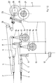
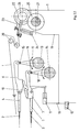
- FIG. 1 schematically shows an embroidery site with such an embroidery site circuit.
- the needle (2) or drill (3) are held in the needle carrier (4) or drill carrier (5) and guided axially.
- the needle pawl (6) or the drill pawl (7) they can be coupled or uncoupled to the needle drive tube (15) or drill drive tube (16).
- Fig. 1.1 shows the pawls in the coupled
- Fig. 1.2 in the uncoupled state.
- the drive tubes (15, 16) are firmly connected to the corresponding drive shaft (13, 14) by means of supports (17, 18). In the coupled state, the oscillating movement of the drive shaft (13, 14) is converted into a linear movement of the corresponding tool (2, 3).
- the embroidery thread (1) is fed to the needle (2) via a thread brake roller (22) and the thread guide (20).
- the thread brake roller (22) is coupled to the thread brake shaft (21) passing through all the embroidery points via pinion (26) and gear (25).
- the thread brake shaft (21) can be braked or driven centrally so as to regulate the thread tension and thread delivery.
- the thread brake roller (22) is mounted on the one-armed thread brake lever (23). In Fig. 1.1 the thread brake roller (22) is coupled to the thread brake shaft (21).
- the actuator (24) the thread brake lever (26) is raised and the pinion (26) and gear (25) are disengaged, whereby the thread brake roller (22) is decoupled from the thread brake shaft (21).
- further actuators of an embroidery location can be activated or deactivated, or coupled or uncoupled to their respective drives, by further actuators.
- One switching element (12) is provided for each embroidery point, which is connected to the actuators (8, 9, 24) by means of appropriate connections (19) (electrical cables, compressed air or hydraulic hoses, ). With a switching of the switching element (12) all actuators (8, 9, 24) of this embroidery point are actuated simultaneously and in the same direction, ie the embroidery point is switched on or off as a whole.
- the connections (19) can be arranged very flexibly, so that no consideration of the common switching has to be taken into account when arranging the tools in an embroidery location.
- Line A represents the beginning of the linearly arranged embroidery points numbered from 1. Depending on the machine length, the number is approximately 100 to 700 embroidery points.
- Line B shows a specific repeat circuit, in this case a three repeat (in embroidery terms a 12/4 repeat), whereby only the first of three needles is embroidered. If you now switch from needle combination A to needle combination B, all the previous embroidery positions had to be reset to a basic position (ON or OFF). Only then could the new combination (eg B) be switched. With the new solution with actuators with fixed end positions, it is first determined in a simple program by comparing combination B and combination C which embroidery points can remain in their switching state (eg embroidery points No. 1, 2, 6, 7, 8, 12 .. .), or which must be switched on (No. 3, 5, 9, 11) or switched off (4, 10). This procedure results in a much shorter changeover time to a different combination of embroidery positions. At the same time, the number of switching operations and thus the necessary switching energy is significantly reduced.
- switching element is understood to mean a pure switching element without force, such as, for example, actuating elements which serve to switch and control a material or energy flow, such as, for example, hydraulic or pneumatic reusable valves, electrical switches and the like.
Landscapes
- Engineering & Computer Science (AREA)
- Textile Engineering (AREA)
- Sewing Machines And Sewing (AREA)
Priority Applications (5)
| Application Number | Priority Date | Filing Date | Title |
|---|---|---|---|
| EP93111062A EP0634512A1 (fr) | 1993-07-10 | 1993-07-10 | Commande et entrainement d'unités de broderie |
| US08/111,135 US5404823A (en) | 1993-07-10 | 1993-08-24 | Embroidery machine including a control element at each embroidery location |
| KR1019930017099A KR950003514A (ko) | 1993-07-10 | 1993-08-31 | 자수기 |
| CH02590/93A CH688052A5 (de) | 1993-07-10 | 1993-09-01 | Stickstellenantrieb und -Schaltung fuer Stickmaschinen. |
| JP5223383A JP2574116B2 (ja) | 1993-07-10 | 1993-09-08 | 刺繍機 |
Applications Claiming Priority (1)
| Application Number | Priority Date | Filing Date | Title |
|---|---|---|---|
| EP93111062A EP0634512A1 (fr) | 1993-07-10 | 1993-07-10 | Commande et entrainement d'unités de broderie |
Publications (1)
| Publication Number | Publication Date |
|---|---|
| EP0634512A1 true EP0634512A1 (fr) | 1995-01-18 |
Family
ID=8213061
Family Applications (1)
| Application Number | Title | Priority Date | Filing Date |
|---|---|---|---|
| EP93111062A Withdrawn EP0634512A1 (fr) | 1993-07-10 | 1993-07-10 | Commande et entrainement d'unités de broderie |
Country Status (5)
| Country | Link |
|---|---|
| US (1) | US5404823A (fr) |
| EP (1) | EP0634512A1 (fr) |
| JP (1) | JP2574116B2 (fr) |
| KR (1) | KR950003514A (fr) |
| CH (1) | CH688052A5 (fr) |
Cited By (5)
| Publication number | Priority date | Publication date | Assignee | Title |
|---|---|---|---|---|
| EP0911437A1 (fr) * | 1997-10-27 | 1999-04-28 | Franz Lässer AG | Machine à broder, en particulier de type Schiffli, avec guide fil mobile |
| CH702907A1 (de) * | 2010-03-26 | 2011-09-30 | Laesser Ag | Schalteinheit zum Zu- und Abschalten eines stichbildenden Organs einer Stick-, Näh- oder Steppmaschine, sowie Stick-, Näh- oder Steppmaschine. |
| EP2381023A1 (fr) | 2010-04-23 | 2011-10-26 | Lässer AG | Machine à broder à plusieurs têtes d'aiguille et procédé de fonctionnement d'une machine à broder à plusieurs têtes d'aiguille |
| DE102012021343A1 (de) * | 2012-10-31 | 2014-04-30 | Saurer Ag | Nadelantrieb für eine Stickmaschine |
| EP3260590A1 (fr) | 2016-06-22 | 2017-12-27 | Forster Rohner Ag | Dispositif d'alimentation pour l'alimentation contrôlée d'un moyen longitudinal, utilisation d'un dispositif d'alimentation et machine de brodage avec dispositif d'alimentation |
Families Citing this family (4)
| Publication number | Priority date | Publication date | Assignee | Title |
|---|---|---|---|---|
| US7607312B2 (en) | 2005-05-27 | 2009-10-27 | Maytag Corporation | Insulated ice compartment for bottom mount refrigerator with temperature control system |
| KR100698704B1 (ko) * | 2006-03-28 | 2007-03-23 | 삼성에스디아이 주식회사 | 데이터 구동부 및 이를 이용한 유기전계발광 표시장치 |
| EP2192221B1 (fr) * | 2008-11-26 | 2017-04-05 | Nähmaschinenfabrik Emil Stutznäcker GmbH & Co. KG | Machine à coudre à plusieurs aiguilles |
| CN106165945A (zh) | 2016-08-25 | 2016-11-30 | 青岛歌尔声学科技有限公司 | 一种滑动式锁止扣 |
Citations (9)
| Publication number | Priority date | Publication date | Assignee | Title |
|---|---|---|---|---|
| CH402585A (it) * | 1963-12-14 | 1965-11-15 | Comerio Ercole Spa | Dispositivo per la messa fuori servizio e viceversa di aghi e boccali operatori nelle macchine da ricamo a telaio automatiche |
| DE2114820A1 (en) * | 1970-12-04 | 1972-06-15 | Comerio Ercole SpA, Busto Arsi zio, Varese (Italien) | Needle selective actuator - tripping embroidering needle(s) to produce pattern |
| US3724405A (en) * | 1970-07-15 | 1973-04-03 | Penn Novelty Co | Color change mechanism for an embroidering machine |
| DE3047928A1 (de) * | 1980-12-19 | 1982-07-01 | Maschinenfabrik Carl Zangs Ag, 4150 Krefeld | Stickmaschine |
| EP0106554A2 (fr) * | 1982-09-20 | 1984-04-25 | Hiraoka Kogyo Kabushiki Kaisha | Appareil de contrôle pour machine à broder |
| CH651081A5 (de) * | 1981-02-04 | 1985-08-30 | Saurer Ag Adolph | Stickmaschine. |
| DE3502887A1 (de) * | 1985-01-29 | 1986-07-31 | Rudolf 5450 Neuwied Reich | Stickmaschine |
| CH660892A5 (de) * | 1982-03-29 | 1987-05-29 | August Heinzle | Schiffchenstickmaschine. |
| JPH0441763A (ja) * | 1990-02-10 | 1992-02-12 | Hiraoka Kogyo Kk | 刺しゅう機に於ける切換機構 |
Family Cites Families (7)
| Publication number | Priority date | Publication date | Assignee | Title |
|---|---|---|---|---|
| US1162009A (en) * | 1912-07-09 | 1915-11-30 | Robert Zahn | Embroidering-machine. |
| DE2900804A1 (de) * | 1979-01-11 | 1980-07-24 | Reich Geb Boettger Elfriede | Einrichtung zum besticken von warenbahnflaechen durch einen oder mehrere flaechen-stickkoepfe mit rapport |
| US4366767A (en) * | 1980-01-28 | 1983-01-04 | Knoos Stellan P | Steering control system for the steering of a boat |
| CH651333A5 (de) * | 1981-02-04 | 1985-09-13 | Saurer Ag Adolph | Stelleinrichtung fuer eine mechanische schalthebelanordnung an einer stickmaschine. |
| CH659499A5 (de) * | 1983-06-16 | 1987-01-30 | Saurer Ag Adolph | Schaltbare bremseinrichtung fuer die faeden einer stickmaschine. |
| CH662140A5 (de) * | 1983-10-06 | 1987-09-15 | Saurer Ag Adolph | Stickmaschine. |
| CH661950A5 (de) * | 1983-10-06 | 1987-08-31 | Saurer Ag Adolph | Stickmaschine. |
-
1993
- 1993-07-10 EP EP93111062A patent/EP0634512A1/fr not_active Withdrawn
- 1993-08-24 US US08/111,135 patent/US5404823A/en not_active Expired - Fee Related
- 1993-08-31 KR KR1019930017099A patent/KR950003514A/ko active IP Right Grant
- 1993-09-01 CH CH02590/93A patent/CH688052A5/de not_active IP Right Cessation
- 1993-09-08 JP JP5223383A patent/JP2574116B2/ja not_active Expired - Lifetime
Patent Citations (9)
| Publication number | Priority date | Publication date | Assignee | Title |
|---|---|---|---|---|
| CH402585A (it) * | 1963-12-14 | 1965-11-15 | Comerio Ercole Spa | Dispositivo per la messa fuori servizio e viceversa di aghi e boccali operatori nelle macchine da ricamo a telaio automatiche |
| US3724405A (en) * | 1970-07-15 | 1973-04-03 | Penn Novelty Co | Color change mechanism for an embroidering machine |
| DE2114820A1 (en) * | 1970-12-04 | 1972-06-15 | Comerio Ercole SpA, Busto Arsi zio, Varese (Italien) | Needle selective actuator - tripping embroidering needle(s) to produce pattern |
| DE3047928A1 (de) * | 1980-12-19 | 1982-07-01 | Maschinenfabrik Carl Zangs Ag, 4150 Krefeld | Stickmaschine |
| CH651081A5 (de) * | 1981-02-04 | 1985-08-30 | Saurer Ag Adolph | Stickmaschine. |
| CH660892A5 (de) * | 1982-03-29 | 1987-05-29 | August Heinzle | Schiffchenstickmaschine. |
| EP0106554A2 (fr) * | 1982-09-20 | 1984-04-25 | Hiraoka Kogyo Kabushiki Kaisha | Appareil de contrôle pour machine à broder |
| DE3502887A1 (de) * | 1985-01-29 | 1986-07-31 | Rudolf 5450 Neuwied Reich | Stickmaschine |
| JPH0441763A (ja) * | 1990-02-10 | 1992-02-12 | Hiraoka Kogyo Kk | 刺しゅう機に於ける切換機構 |
Non-Patent Citations (1)
| Title |
|---|
| PATENT ABSTRACTS OF JAPAN vol. 16, no. 219 (C - 0943) 22 May 1992 (1992-05-22) * |
Cited By (10)
| Publication number | Priority date | Publication date | Assignee | Title |
|---|---|---|---|---|
| EP0911437A1 (fr) * | 1997-10-27 | 1999-04-28 | Franz Lässer AG | Machine à broder, en particulier de type Schiffli, avec guide fil mobile |
| CH702907A1 (de) * | 2010-03-26 | 2011-09-30 | Laesser Ag | Schalteinheit zum Zu- und Abschalten eines stichbildenden Organs einer Stick-, Näh- oder Steppmaschine, sowie Stick-, Näh- oder Steppmaschine. |
| EP2381023A1 (fr) | 2010-04-23 | 2011-10-26 | Lässer AG | Machine à broder à plusieurs têtes d'aiguille et procédé de fonctionnement d'une machine à broder à plusieurs têtes d'aiguille |
| CH703065A1 (de) * | 2010-04-23 | 2011-10-31 | Laesser Ag | Stickmaschine und Verfahren zum Betreiben einer Stickmaschine. |
| CN102234882A (zh) * | 2010-04-23 | 2011-11-09 | 拉瑟股份公司 | 多针头刺绣机以及操作该多针头刺绣机的方法 |
| CN102234882B (zh) * | 2010-04-23 | 2015-09-09 | 拉瑟股份公司 | 多针头刺绣机以及操作该多针头刺绣机的方法 |
| DE102012021343A1 (de) * | 2012-10-31 | 2014-04-30 | Saurer Ag | Nadelantrieb für eine Stickmaschine |
| DE102012021343B4 (de) * | 2012-10-31 | 2015-03-05 | Saurer Ag | Nadelantrieb für eine Stickmaschine |
| EP3260590A1 (fr) | 2016-06-22 | 2017-12-27 | Forster Rohner Ag | Dispositif d'alimentation pour l'alimentation contrôlée d'un moyen longitudinal, utilisation d'un dispositif d'alimentation et machine de brodage avec dispositif d'alimentation |
| WO2017220303A1 (fr) | 2016-06-22 | 2017-12-28 | Forster Rohner Ag | Dispositif d'alimentation pour acheminer de manière contrôlée un produit oblong, utilisation d'un dispositif d'alimentation et machine à broder dotée d'un dispositif d'alimentation |
Also Published As
| Publication number | Publication date |
|---|---|
| JPH0726464A (ja) | 1995-01-27 |
| CH688052A5 (de) | 1997-04-30 |
| KR950003514A (ko) | 1995-02-17 |
| US5404823A (en) | 1995-04-11 |
| JP2574116B2 (ja) | 1997-01-22 |
Similar Documents
| Publication | Publication Date | Title |
|---|---|---|
| EP0634512A1 (fr) | Commande et entrainement d'unités de broderie | |
| CH655034A5 (de) | Einrichtung an einer maschine zur steuerung bzw. ueberwachung. | |
| DE3811330A1 (de) | Tuftingmaschine | |
| EP2381023B1 (fr) | Machine à broder à plusieurs têtes d'aiguille et procédé de fonctionnement d'une machine à broder à plusieurs têtes d'aiguille | |
| DE2940202A1 (de) | Webmaschine | |
| DE19615671C2 (de) | Vorrichtung zur Herstellung von Kettenwirkware mit zwei voneinander unabhängigen Wirkbereichen | |
| DE4308251A1 (de) | Textilmaschine | |
| EP0784111A2 (fr) | Elément de couplage de cadre avec dispositif de déverrouillage | |
| WO2003089815A1 (fr) | Unite de changement de vitesses electropneumatique | |
| DE3228434A1 (de) | Kupplungsvorrichtung fuer die energiezufuhr zu auswechselbaren arbeitseinheiten einer spritzgiessmaschine | |
| EP0617744B1 (fr) | Dispositif de commande pour un fil d'une machine textile | |
| DE3436034A1 (de) | Stickmaschine | |
| EP1012364B1 (fr) | Dispositif de commande de fil | |
| EP0866928B1 (fr) | Commande de boite de vitesses a synchro-baladeur ou boite de vitesses couplable sous charge | |
| EP0601343A2 (fr) | Métier à broder à entraînement central | |
| EP0638681B1 (fr) | Machine à broder à navettes | |
| DE3436017A1 (de) | Stickmaschine | |
| DE19538937C2 (de) | Strickmaschine mit einzeln angetriebenen Nadeln | |
| DE10251627A1 (de) | Schalteinheit | |
| EP0911437B1 (fr) | Machine à broder, en particulier de type Schiffli, avec guide fil mobile | |
| DE3222716C2 (de) | Nähvorrichtung | |
| DE2704855A1 (de) | Verfahren und vorrichtung zum stangenwechsel bei mehrstangengeraeten fuer stick-, naeh- und steppmaschinen | |
| EP1552048B1 (fr) | Procede de maintien d'un fil de trame ; machine a tisser a tuyeres munie d'un dispositif de serrage pour fil de trame, s'utilisant notamment pour mettre ledit procede en oeuvre et cartouche sous forme d'unite modulaire rempla able a inserer dans le tube melangeur d'une machine a tisser a tuyeres | |
| DE2334134A1 (de) | Stickmaschine | |
| DE3447884A1 (de) | Mikrorechnersteuereinheit fuer eine strickmaschine, insbesondere fuer eine flachstrickmaschine |
Legal Events
| Date | Code | Title | Description |
|---|---|---|---|
| PUAI | Public reference made under article 153(3) epc to a published international application that has entered the european phase |
Free format text: ORIGINAL CODE: 0009012 |
|
| AK | Designated contracting states |
Kind code of ref document: A1 Designated state(s): AT DE FR IT |
|
| RIN1 | Information on inventor provided before grant (corrected) |
Inventor name: ZESCH, MANFRED Inventor name: HENZ, JUERG, DR. Inventor name: ABEGGLEN, HANS |
|
| 17P | Request for examination filed |
Effective date: 19950425 |
|
| 17Q | First examination report despatched |
Effective date: 19961029 |
|
| STAA | Information on the status of an ep patent application or granted ep patent |
Free format text: STATUS: THE APPLICATION HAS BEEN WITHDRAWN |
|
| 18W | Application withdrawn |
Withdrawal date: 19970411 |