EP0634102B1 - Abbildungssystem zur Behandlung von transversal geschnittenen Fisch-Sektionen - Google Patents
Abbildungssystem zur Behandlung von transversal geschnittenen Fisch-Sektionen Download PDFInfo
- Publication number
- EP0634102B1 EP0634102B1 EP94110212A EP94110212A EP0634102B1 EP 0634102 B1 EP0634102 B1 EP 0634102B1 EP 94110212 A EP94110212 A EP 94110212A EP 94110212 A EP94110212 A EP 94110212A EP 0634102 B1 EP0634102 B1 EP 0634102B1
- Authority
- EP
- European Patent Office
- Prior art keywords
- fish
- section
- camera
- cameras
- shrouds
- Prior art date
- Legal status (The legal status is an assumption and is not a legal conclusion. Google has not performed a legal analysis and makes no representation as to the accuracy of the status listed.)
- Expired - Lifetime
Links
- 241000251468 Actinopterygii Species 0.000 title claims description 83
- 238000003384 imaging method Methods 0.000 title claims description 32
- 230000002093 peripheral effect Effects 0.000 claims description 6
- 238000012216 screening Methods 0.000 claims description 2
- 238000000034 method Methods 0.000 description 12
- 235000013372 meat Nutrition 0.000 description 8
- 239000012530 fluid Substances 0.000 description 6
- 240000007320 Pinus strobus Species 0.000 description 4
- 239000008280 blood Substances 0.000 description 4
- 210000004369 blood Anatomy 0.000 description 4
- 238000005286 illumination Methods 0.000 description 4
- 230000009278 visceral effect Effects 0.000 description 3
- 210000000988 bone and bone Anatomy 0.000 description 2
- 238000005266 casting Methods 0.000 description 2
- 238000010411 cooking Methods 0.000 description 2
- 239000002699 waste material Substances 0.000 description 2
- XLYOFNOQVPJJNP-UHFFFAOYSA-N water Substances O XLYOFNOQVPJJNP-UHFFFAOYSA-N 0.000 description 2
- 210000001015 abdomen Anatomy 0.000 description 1
- 230000000694 effects Effects 0.000 description 1
- 230000008030 elimination Effects 0.000 description 1
- 238000003379 elimination reaction Methods 0.000 description 1
- 239000000835 fiber Substances 0.000 description 1
- 239000002184 metal Substances 0.000 description 1
- 230000002250 progressing effect Effects 0.000 description 1
- 238000000926 separation method Methods 0.000 description 1
- 238000010025 steaming Methods 0.000 description 1
- 238000010257 thawing Methods 0.000 description 1
- 210000001835 viscera Anatomy 0.000 description 1
Images







Classifications
-
- A—HUMAN NECESSITIES
- A22—BUTCHERING; MEAT TREATMENT; PROCESSING POULTRY OR FISH
- A22B—SLAUGHTERING
- A22B5/00—Accessories for use during or after slaughtering
- A22B5/0064—Accessories for use during or after slaughtering for classifying or grading carcasses; for measuring back fat
- A22B5/007—Non-invasive scanning of carcasses, e.g. using image recognition, tomography, X-rays, ultrasound
-
- A—HUMAN NECESSITIES
- A22—BUTCHERING; MEAT TREATMENT; PROCESSING POULTRY OR FISH
- A22C—PROCESSING MEAT, POULTRY, OR FISH
- A22C25/00—Processing fish ; Curing of fish; Stunning of fish by electric current; Investigating fish by optical means
-
- Y—GENERAL TAGGING OF NEW TECHNOLOGICAL DEVELOPMENTS; GENERAL TAGGING OF CROSS-SECTIONAL TECHNOLOGIES SPANNING OVER SEVERAL SECTIONS OF THE IPC; TECHNICAL SUBJECTS COVERED BY FORMER USPC CROSS-REFERENCE ART COLLECTIONS [XRACs] AND DIGESTS
- Y10—TECHNICAL SUBJECTS COVERED BY FORMER USPC
- Y10T—TECHNICAL SUBJECTS COVERED BY FORMER US CLASSIFICATION
- Y10T83/00—Cutting
- Y10T83/525—Operation controlled by detector means responsive to work
- Y10T83/533—With photo-electric work-sensing means
Definitions
- the present invention relates to fish processing and more particularly to a improved method and apparatus for processing a fish body that has been cut into a plurality of transverse fish body sections, and more particularly relates to an improved imaging apparatus that features imaging of both sides of a transverse fish slab section using automated illumination and background screening to produce an improved image of each of the opposed sides of a fish body section.
- tuna In the processing of fish such as tuna, it is common to freeze a catch of fish at sea, and to process the catch on shore.
- the processing normally involves thawing the fish followed by manual operations of slicing the fish belly and the removal of viscera.
- the visceral cavity is then washed with water, and the tuna inspected for spoilage.
- the tuna is then usually cooked whole in a batch type precooking operation.
- U.S. Patent 3,800,363 issued to J.M. Lapeyre entitled “Tuna Butchering Method and System” describes an automated butchering method and system for separating the edible loin portions of transverse tuna slices provided by subdivision of a frozen whole tuna.
- the present invention solves the aforementioned problem with the features of claim 1, and provides an improved imaging apparatus for processing transversely cut sections (such as transversely cut fish sections) which have generally flat opposing surfaces and a peripheral curved outer surface.
- the apparatus includes a support frame having a pair of spaced-apart shrouds mounted thereon, each of the shrouds having a hollow bore with a central longitudinal axis.
- the central longitudinal axes of the bores can be aligned.
- a pair of video cameras are mounted respectively within the bores of the two shrouds. Each video camera defines a line of sight that generally tracks the central longitudinal portion of its shroud.
- Half of this system can be used (i.e. a single video camera and a single shroud), and the section rotated about a known axis so that the camera takes a video image of each side.
- Another alternative embodiment can use the image from a prior adjacent transversely cut slab for one side of the present slab. This can be done where several transversely cut slabs are being processed in an assembly line. The slabs are cut from a fish body in sequence beginning at one end and progressing to the other end.
- a gap between the shrouds defines a target area that is adapted to receive the fish body section to be processed.
- a holder supports a fish body section to be processed in a position that enables one of the cameras to view one of the flat opposing surfaces of the fish section and the other camera to view the other flat surface of the fish section.
- a line of sight intersects the fish body section and also generally defines the central longitudinal axis of each of the shrouds.
- Means for maintaining the holder in the same position with respect to the line of sight ensures that the images of the fish body sections are referenced to a common frame of reference.
- a illumination system that comprises a plurality of light sources that illuminates all portions of the fish body section. At least some of the light sources are angularly oriented with respect to the line of sight so that the interface between one of the flat surfaces and the peripheral curved edge of the fish body section is enhanced by selectively casting shadows upon the curved edge.
- Some of the light sources emit diffuse light, which is reflected by a reflector to illuminate a flat surface of the fish body section.
- a pair of screens rotate between engaged and disengaged positions.
- a screen is provided for each side of the fish body section so that when one camera is viewing a flat side of the fish body section, a screen is placed behind the fish body section to act as a black backdrop.
- each screen is extended and retracted by an individual pressure-actuated cylinder and is mechanically isolated from the shrouds so that either of the two screens can be placed in position to act as a backdrop for one of the two video cameras without vibrating the imaging apparatus.
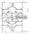
- Figures 1-5 illustrate generally the preferred embodiment of the apparatus of the present invention designated generally by the numeral 10.
- Imaging apparatus 10 for use in processing transversely cut fish sections includes a frame 11 having feet 12 which can rest upon an underlying floor 13, such as for example, a shop floor or the like.
- First and second cylindrical shrouds 14, 15 are supported upon frame 11. Each cylindrical shroud 14, 15 provides an outer wall and an internal cylindrical bore 16, 17 respectively. Shroud walls 18, 19 can be of sheet metal, for example. A gap 20 between the shrouds 14, 15 allows background sheets 29, 30 to be placed behind a transverse section 25 during imaging.
- Holder 21 includes a vertical strut 22 with indexing pins 23 thereon.
- the indexing pins 23 are vertically spaced apart during use.
- Pins 23 affix holder 21 in a known position.
- Holder support 24 is secured to wall 18.
- Holder 21 supports a fish section 25 in a generally vertical orientation so that the opposed surfaces 26, 27 of the transverse fish slab section 25 are generally vertically oriented and at right angles to the camera line of sight.
- the opposed surfaces 26, 27 communicate with a peripheral curved surface 28 (e.g., the skin of the fish if not yet removed).
- background screen sheets 29, 30 are sequentially positioned behind the transverse fish section 25 while an image is being taken of the fish section surface 26 or 27, as selected. Sheets 29, 30 are preferably black in color. One of the background sheets 29, 30 is in position behind the fish section opposite the position of the camera that is imaging the opposed surface 26 or 27.
- Each background sheet 29, 30 can be mounted to a rotating bushing 31, 32, each of which is attached to rotary shaft 33, rotating therewith. The shaft 33 is rotated using link 34 that is powered with pushrod 35 extending from extensible fluid cylinder 36.
- Cylinder 36 can be hydraulically, pneumatically, or electrically operated. Extensible cylinder 36 is attached at cylinder end support 37 to frame 11.
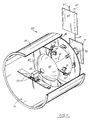
- Each shroud 14, 15 provides a forward baffle plate 38, 39 and a rear baffle plate 40, 41. Openings 42, 43 allow lighting and the video image to pass through the rear baffle plates as shown. Concave/convex members 44, 45 are mounted upon the baffle plates 40, 41 respectively, as shown in Figure 2. Openings 46, 47 respectively are provided in concave/ convex members 44, 45 so that the line of sight 50, 51 is provided between the fish section 25 and each video camera 48, 49. Lighting sources (in the form of strobes, for example) 52, 53, 54, 55 are provided for illuminating the opposed surfaces 26, 27 of the transverse fish slab section 25.
- a plurality of rear light sources 52, 53 is provided, as well as a plurality of forward light sources 54, 55 respectively in the two shrouds 14, 15.
- Each camera 48, 49 is supported upon a camera support 56, 57 respectively.
- a scanned image of the first opposing surface 26 is taken with the surface illuminated uniformly by diffuse lighting emitted by rear light sources 52 and reflected off the concave surface of concave/convex member 44.
- Forward light sources 54 direct light obliquely at edge portions of the first opposing surface 26 to illuminate the surface portion brightly, while casting a shadow at the edge and beyond. In this way accurate images of the edges (i.e., the skin) are obtained. If skinning is not required, edge images need not be taken.
- Diffuse lighting can be provided by fluorescent sources and a single image of the first opposing surface 26 taken without the need for sequential strobing.
- the video camera 48 first scans the first opposing surface 26 with background sheet 29 in position behind the fish slab section 25 to produce an image of the first surface 126.
- the fish slab 25 is shown held by the holder 31 and with the background sheet member 29 in position.
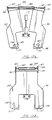
- Figure 4 shows the view that is seen by camera 48.
- the background sheet 29 has been rotated away from the fish slab section 25 and the background sheet 30 has been moved into position so that the camera 49 is now viewing opposed surface 27 of fish slab section 25 along line of sight 51.
- a second embodiment of the apparatus of the present invention is designated generally by the numeral 60.
- a slab 25 is supported upon holder 64, vertically referenced by a positioner 61 in the form of a cylinder having an extensible pushrod 62 extending through carrier 63 to support holder 64.
- Carrier 63 on conveyor rails 74, carries a transverse slab 25 impaled on holder 64 into position above positioner 61.
- the pushrod 62 pushes the holder 64 up through the carrier 63 until the slab 25 is positioned to be viewed by a video camera 48 or 49.
- a pair of screens 65, 66 are respectively mounted upon pushrods 67, 69.
- the pushrods are movable between engaged ad disengaged positions as shown by the movement of arrows 68 and 69 in Figure 6.
- the arrow 70 shows an extended, operative position wherein the screen 66 is shown behind the fish slab 25.
- Arrow 68 illustrates a retracted position of screen 65.
- the camera 68 is imaging a side of the slab 25 with the help of illumination provided by strobes 52, 54.
- the screen 66 would be withdrawn and the screen 68 moved into a position behind the slab 25 to form a backdrop for the video imaging of the slab 25.
- the strobes 53, 55 provide illumination and the screen 65 forms a backdrop.
- the pushrods 67, 69 are operated with a pair of pressure-actuated cylinders 71, 72 which can be pneumatic or hydraulic. Cylinders 71, 72 are anchored to a suitable support 73, preferably mechanically isolated from the rest of the imaging system 60.
- FIG. 8-9 Another embodiment of the imaging apparatus of the invention is shown in Figures 8-9.
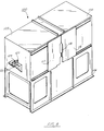
- This embodiment of the apparatus 100 differs from those shown in Figures 1-7 in that shrouds 102, 103 are principally parallelepipeds rather than cylinders.
- reflectors 104, 105 are flat plates (e.g., the backs of the shrouds 102, 103) rather than concave/convex members.
- the shrouds 102, 103 are mounted on a support frame 106.
- Cameras 108, 109 are mounted on stands 124, 125 at the ends of the shrouds 102, 103 and view the target area along longitudinal lines of sight 110, 111 through a central hole 126, 127 in each reflector 104, 105.
- Rearward-facing light sources 112, 113 provide diffuse light reflected off the reflectors 104, 105 for uniformly illuminating the flat surfaces 120, 121 of the fish section 119.
- Forward-facing light sources 114, 115 obliquely illuminate individual portions of the flat surfaces 120, 121 to provide a sharp image of the edges, i.e., the skin.
- Slidable side doors 116, 117 on each side of the apparatus 100 permit access for servicing. When closed, the doors 116, 117 define a port 118 through which the fish section 119 can be conveyed along rails 74.
- a backdrop (not shown in Figure 9) is provided by screens 65, 66 as in Figure 6.
- a device for gripping the holder 64 to maintain the fish body section 119 in known registered position with respect to the lines of sight 110, 111 of the cameras 108, 109 during the imaging process is supported on a support 131 attached to one of the shrouds 102. Fingers 132 protruding from the gripping device 130 retain the holder 64 by means of pneumatic pressure, for instance. After imaging, the fingers 132 are retracted, thereby releasing the holder 64 so that the fish body section 119 can be conveyed out of the imaging station by the carrier 63 along rails 74.
- FIG. 10 Yet another embodiment of the parallelepiped imaging station is shown in Figure 10, in which the strobe lights are replaced by vertically oriented fluorescent tubes 140, 141.
- the tubes 140, 141 are mounted in fixtures 142, 143 attached to the back walls 146, 147 of the shrouds 102, 103.
- Diffusers 144, 145 over the tubes 140, 141 diffuse the emitted light to uniformly illuminate the surfaces 120, 121 of the fish body section 119.
- This imaging station is simpler than that of Figure 9 and can be used when imaging of the edges (i.e., the skin) of the fish body section 119 is not required, such as for a skinned fish.
- the vision cooker 150 in Figures 11-13 comprises two shrouds 151, 152 enclosing steam manifolds 153, 154 connected to a controllable source of steam (not shown) via steam lines 155, 156.
- the shrouds 151, 152 are pivotally pinned at their bottom corners to blocks 157 by pivot pins 158.
- Flanges 159-162 attached to the upper corners of the shrouds 151, 152 extend outward and upward of the shrouds 151, 152.
- Pushrods 167, 168 extending from pneumatic cylinders 163, 164 are pivotally attached at opposing pairs of flanges 159, 160 and 161, 162 by pivot joints 165.
- a source of pneumatic pressure (not shown) operates the cylinders 163, 164 through air lines 166.
- the pushrods 167, 168 are pushed out of the cylinders, thereby exerting a force against the flanges 159-162, which causes the shrouds 151, 152 to pivot open about the pivot pins 158 as indicated by arrows 169.
- the fish body section 119 can be conveyed into or out of the steam chamber 170 by carrier 63 along rails 74.
- the pneumatic pressure is reduced to close the shrouds 151, 152, thereby enclosing the fish body section 119 with its surfaces 120, 121 close to the steam exit holes 172 of the manifolds 153, 154.
- Steam 171 impinging on the surfaces 120, 121 thaws the sheared meat fibers and allows them to rehydrate, which increases the contrast between the light loin portions and the dark blood meat portions. Only a few seconds of steaming is required to adequately produce the desired contrast.
- Exhaust steam exits through the opening 173 in the top of the vision cooker 150.
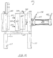
- FIGs 11-13 illustrate another embodiment of the vision cooking apparatus of the present invention designated generally by the numeral 210.
- Flash cooker apparatus 210 includes a flame 211 having a plurality of legs 212 with a plurality of feet 213 respectively.
- the frame includes transversely extending beams 214 and 215.
- Bolted connections 216, 217 secure the beams 214 and 215 to the legs 212 as shown in Figure 11.
- a fluid cylinder 218 such as a pneumatic cylinder is provided for moving a first moving shroud 225 with respect to a fixed shroud 240.
- Flow lines 219, 220 transmit fluid to and from fluid cylinder 218 for powering the extensible pushrod 223 portion thereof as shown by the arrows 221 and 222 in Figure 13.
- the arrow 221 indicates the flow of fluid to cylinder 218 via flowline 220.
- the arrows 222 indicate the movement of extensible pushrod 223 and its attached moving shroud 225 toward a closed position.
- the closed position is shown in Figure 13.
- the open position is shown with arrows 237 indicating an opening movement of shroud 225 with respect to the fixed shroud 240.
- the moving shroud 225 includes rear wall 226, side walls 227, top wall 228, and bottom wall 229.
- the shroud 225 is thus generally rectangular, in the form of a rectangular box with the front, rear, side, and bottom walls being orthogonally connected. Upon closure the shrouds form a box-like enclosure about the fish section to be processed.
- a steam inlet opening 230 communicates with detachable connection 231 to steam inlet line 232.
- Arrow 233 designates the flow of steam into the shrouds 225, 240 when in the closed position of Figure 13.
- the moving shroud 225 can have a pair of spaced apart wheels 234 mounted upon axle 235.
- Recess 236 in top wall accommodates holder 250 when the moving shroud 225 assumes the closed position of Figure 13.
- Arrow 238 in Figure 12 indicates the flow of fluid via flowline 219 into cylinder 218 for moving the extensible pushrod 223 to an inward most retracted position as shown in Figure 12.
- the arrows 237 designate movement of shroud 225 away from fixed shroud 240.
- the fixed shroud 240 includes top wall 241, side walls 242, and bottom walls 243.
- Shroud 240 is preferably similarly shaped and sized to the moving shroud 225 so that the two shrouds form a rectangular box like enclosure about the fish section to be processed when in the closed position of Figure 13.
- Arrow 245 in Figure 13 illustrates the flow of steam into fixed shroud 240 via steam inlet opening 244.
- Steam flowline 246 can be removably attached to inlet 244 using a removable connection for example.
- Holder support bracket 247 includes a pair of spaced apart, generally horizontally extending indexing pins 248, 249 which accommodate holder 250.
- Holder 250 includes a pivoting portion 251 and a blade handle 252.
- a holder such as holder 64 and carriage 63 as in Figure 6 could be used to transport the fish section 253 into and out of the cooker 210 and to support it in place during cooking.
- the holder 250 can grip a transversely cut fish section 253 so that the front flat surface of fish section 255 and the rear flat surface of fish section 253 respectively face the shrouds 225, 240. In this position, the peripheral surface 256 of the fish section 253 faces side walls 227 and 242.
- Each shroud 225, 240 carries a perforated steam panel 257 with a plurality of openings 258 extending over the surface of plate 257 in array form as shown in Figure 11.
- the steam panels 257 are designed to fit closely against the surfaces 254, 255 of the fish section 253 when the shrouds 225, 240 are in a closed position. In this fashion, steam exits each of the plurality of openings 258 producing a uniform precook to at least the outer surface of each flat surface 254, 255 of the fish section 253 which is preferably frozen.
- frozen fish sections 253 are preliminarily cooked in a flash or quick cook fashion so that only the very outermost surfaces 254, 255 are thawed and cooked, producing greater contrast between the lighter edible meat portion as compared with the darker blood meat, bone, and visceral portions of the fish section 253.
- the fish section 253 still remains frozen and stiff, because only a very thin outer layer at each surface 254, 255 is thawed and cooked. This contrast helps in the imaging of each fish section so that a computer can translate the video information into cutting information for an automated cutting knife.
- the aforedescribed improved imaging system provides improved image quality which enhances the accuracy and precision with which a water jet knife can cut the transverse fish slab section 25 as described, for example, in prior U.S. Patent No. 4,748,724 and U.S. Patent No. 4,847,954.
- the support technique provides faster and less involved throughput of transverse fish sections through the visioning/imaging apparatus.
Landscapes
- Engineering & Computer Science (AREA)
- Life Sciences & Earth Sciences (AREA)
- Food Science & Technology (AREA)
- Computer Vision & Pattern Recognition (AREA)
- Biophysics (AREA)
- Wood Science & Technology (AREA)
- Zoology (AREA)
- Processing Of Meat And Fish (AREA)
- Meat, Egg Or Seafood Products (AREA)
- Image Processing (AREA)
- Studio Devices (AREA)
- Closed-Circuit Television Systems (AREA)
Claims (9)
- Videoabbildungsgerät zur Behandlung von transversal geschnittenen Fischscheibensektionen mit einem eßbaren Teil und einem nichteßbaren Teil, wobei die Sektion ein Paar gegenüberliegende ebene Flächen einschließt, die von einem gekrümmten Randteil umgeben sind, dadurch gekennzeichnet, daß es umfaßt:a) einen Rahmen (11);b) eine Videokamera (48, 49, 108, 109) an jeder Seite des Rahmens;c) ein Aufnahmegebiet, das gestaltet ist, um die Fischsektion aufzunehmen;d) einen Halter (21, 64) zum entfernbaren Halten einer zu behandelnden Fischsektion in einer Position, die einer der Kameras ermöglicht, eine ebene Seite der Fischsektion zu sehen, und der anderen Kamera ermöglicht, die andere Seite der Fischsektion zu sehen.
- Gerät nach Anspruch 1, dadurch gekennzeichnet, daß der Rahmen ein Paar Mantelringe (14, 15, 102, 103) einschließt, die die Videokameras umgeben.
- Gerät nach Anspruch 1, dadurch gekennzeichnet, daß der Halter (21, 64) eine Verbindung mit der Fischkörpersektion an dem Randteil bildet.
- Gerät nach Anspruch 1, dadurch gekennzeichnet, daß das Aufnahmegebiet im allgemeinen zwischen den Kameras (48, 49, 108, 109) und äquidistant zu jeder Kamera positioniert ist, so daß das von jeder Kamera erzeugte Bild ungefähr dieselbe Größe wie das andere erzeugte Bild aufweist.
- Gerät nach Anspruch 1, dadurch gekennzeichnet, daß der Rahmen (11) Mantelringeinrichtungen (14, 15, 102, 103) einschließt, die zu den Kameras entlang einer Längsachse ausgerichtet sind, die die Sichtlinie zwischen jeder Kamera und der zu behandelnden Fischsektion bildet.
- Gerät nach Anspruch 1, dadurch gekennzeichnet, daß der Rahmen ein Paar Mantelringe (14, 15, 102, 103) einschließt, die im allgemeinen entgegengesetzt sind und jeweils zu den Kameras ausgerichtet sind, und jeder Mantelring eine Längsachse aufweist, die eine Sichtlinie zwischen den Kameras und der zu behandelnden Fischsektion bildet.
- Gerät nach Anspruch 1, dadurch gekennzeichnet, daß außerdem eine Hintergrundeinrichtung zur Abschirmung (29, 30, 65, 66) hinter der Fischsektion während der Abbildung vorgesehen ist.
- Gerät nach Anspruch 7, dadurch gekennzeichnet, daß die Hintergrundeinrichtung ein Paar Hintergrundflächen (29, 30, 65, 66) umfaßt, die an dem Rahmen beweglich befestigt sind, so daß eine ausgewählte Fläche hinter der zu betrachtenden Fischsektionsfläche plaziert werden kann.
- Gerät nach Anspruch 1, dadurch gekennzeichnet, daß es außerdem eine Positioniereinrichtung zum Bewegen des Halters (21, 64), der die zu behandelnde Fischsektion hält, in die Position in dem Aufnahmegebiet umfaßt, die einer der Kameras ermöglicht, eine ebene Seite zu sehen, und der anderen Kamera ermöglicht, die andere ebene Seite der Fischsektion zu sehen.
Applications Claiming Priority (2)
| Application Number | Priority Date | Filing Date | Title |
|---|---|---|---|
| US08/090,819 US5352153A (en) | 1993-07-13 | 1993-07-13 | Imaging system for use in processing transversely cut fish body sections |
| US90819 | 1993-07-13 |
Publications (2)
| Publication Number | Publication Date |
|---|---|
| EP0634102A1 EP0634102A1 (de) | 1995-01-18 |
| EP0634102B1 true EP0634102B1 (de) | 1997-05-02 |
Family
ID=22224476
Family Applications (1)
| Application Number | Title | Priority Date | Filing Date |
|---|---|---|---|
| EP94110212A Expired - Lifetime EP0634102B1 (de) | 1993-07-13 | 1994-06-30 | Abbildungssystem zur Behandlung von transversal geschnittenen Fisch-Sektionen |
Country Status (8)
| Country | Link |
|---|---|
| US (1) | US5352153A (de) |
| EP (1) | EP0634102B1 (de) |
| JP (1) | JPH07194343A (de) |
| KR (1) | KR960013210A (de) |
| AU (1) | AU669446B2 (de) |
| CA (1) | CA2127402A1 (de) |
| DE (1) | DE69402915T2 (de) |
| NO (1) | NO942615L (de) |
Families Citing this family (24)
| Publication number | Priority date | Publication date | Assignee | Title |
|---|---|---|---|---|
| US5378194A (en) * | 1993-07-27 | 1995-01-03 | Royal Seafoods, Inc. | Device for processing flat fish |
| US5591076A (en) * | 1995-04-21 | 1997-01-07 | Nordischer Maschinenbau Rud. Baader Gmbh & Co Kg | Apparatus for processing flat fish |
| AU722769B2 (en) * | 1996-08-23 | 2000-08-10 | Her Majesty The Queen In Right Of Canada As Represented By The Department Of Agriculture And Agri-Food Canada | Method and apparatus for using image analysis to determine meat and carcass characteristics |
| DE19906021C2 (de) * | 1999-02-16 | 2003-02-27 | Holger Wente | Verfahren und Vorrichtung zum Abtrennen scheibenförmiger Körper von einem Ursprungskörper |
| DE00928257T1 (de) * | 1999-04-20 | 2005-12-15 | Formax, Inc., Mokena | Gerät zur automatischen abtastung eines produktes sowie aufschnittschneidemaschine mit einem solchen gerät |
| PL354491A1 (en) * | 1999-07-28 | 2004-01-26 | Marine Harvest Norvay Sa | Method and apparatus for determining quality properties of fish |
| GB2364894B8 (en) | 2000-07-19 | 2010-07-07 | Fmc Corp | Three axis portioning method |
| WO2003037090A1 (en) * | 2001-11-01 | 2003-05-08 | Stein Grov Eilertsen | Apparatus and method for trimming of fish fillets |
| DK1583427T3 (da) * | 2003-01-17 | 2007-07-30 | Hans Moeller Rasmussen | Fremgangsmåde til forarbejdning af fileter |
| US7373217B2 (en) * | 2003-04-08 | 2008-05-13 | Hormel Foods, Llc | Apparatus for slicing a food product and method therefore |
| NO319624B1 (no) | 2003-09-15 | 2005-09-05 | Trouw Internat Bv | Fiskefôr for laksefisk i ferskvann og anvendelse av slikt fôr. |
| AU2005213846B2 (en) * | 2004-02-20 | 2010-05-13 | Scanvaegt International A/S | Method and apparatus for portion cutting of food products or similar items |
| NO323529B1 (no) * | 2004-05-13 | 2007-06-04 | Trouw Internat Bv | Framgangsmate for reduksjon av innholdet av uonskede naeringsstoffer i avlopsvann fra fiskeoppdrettsanlegg. |
| IS7959A (is) * | 2004-12-16 | 2006-06-17 | Skaginn Hf. | Athferth og bunathur vith sj βlfvirka beingarthst”ku, skurth meth vatni og snyrtingu β afurth |
| DE102005047752B3 (de) * | 2005-09-28 | 2006-10-05 | Nordischer Maschinenbau Rud. Baader Gmbh + Co Kg | Vorrichtung und Verfahren zum Oberflächentrimmen von Fleisch sowie Vorrichtung zum Verarbeiten von Fleisch mit einer Vorrichtung zum Oberflächentrimmen |
| US7467994B2 (en) * | 2006-08-14 | 2008-12-23 | Terry Cemlyn Griffiths | Variable size carcass contaminant removal |
| BRPI0622044A2 (pt) * | 2006-10-06 | 2014-06-10 | Nordischer Maschinenbau | Método e dispositivo para o processamento de peixes, aves domésticas ou outros produtos de carne de qualquer tipo e forma |
| US7566260B1 (en) * | 2008-09-24 | 2009-07-28 | Terry Cemlyn Griffiths | Split carcass washer |
| US8549996B2 (en) | 2010-05-28 | 2013-10-08 | Dole Fresh Vegetables, Inc. | System for topping and tailing lettuce heads using a camera-guided servo-controlled water knife |
| CA2833488C (en) | 2012-12-19 | 2020-07-28 | Laitram, L.L.C. | Shrimp processing system and methods |
| EP3133927A4 (de) | 2014-04-24 | 2017-10-18 | Laitram, L.L.C. | Verarbeitungssystem für garnelen und verfahren |
| PH12021550342B1 (en) | 2018-08-16 | 2024-05-24 | Thai Union Group Public Co Ltd | Multi-view imaging system and methods for non-invasive inspection in food processing |
| US11120540B2 (en) | 2018-08-16 | 2021-09-14 | Thai Union Group Public Company Limited | Multi-view imaging system and methods for non-invasive inspection in food processing |
| US10881115B1 (en) * | 2019-08-19 | 2021-01-05 | James Ronald Inscho, Jr. | Automated poultry orientation and shackling system |
Family Cites Families (28)
| Publication number | Priority date | Publication date | Assignee | Title |
|---|---|---|---|---|
| US3089775A (en) * | 1959-01-23 | 1963-05-14 | Unilever Ltd | Method of removing meat from bone |
| GB889787A (en) * | 1959-08-07 | 1962-02-21 | Rudolf Georg Theodor Baader | Improvements relating to beheading of fish |
| US3594191A (en) * | 1969-02-14 | 1971-07-20 | James M Lapeyre | Method of processing tuna |
| US3593370A (en) * | 1969-09-19 | 1971-07-20 | James M Lapeyre | Method of butchering tuna |
| US3675273A (en) * | 1970-11-27 | 1972-07-11 | Star Kist Foods | Fish butchering apparatus |
| US3800363A (en) * | 1972-12-29 | 1974-04-02 | Laitram Corp | Tuna butchering method and system |
| US3978748A (en) * | 1974-11-25 | 1976-09-07 | Camsco, Inc. | Fluid jet cutting system |
| US4020528A (en) * | 1975-08-15 | 1977-05-03 | Stig Lindbladh | Method and apparatus for removing skin from salted, seasoned or otherwise pre-treated fish, preferably herring filets |
| US4217679A (en) * | 1978-08-04 | 1980-08-19 | Matthew Gordon | Meat deboning process |
| US4738004A (en) * | 1982-04-05 | 1988-04-19 | The Laitram Corporation | Tuna butchering method |
| US4520702A (en) * | 1982-06-14 | 1985-06-04 | Key Technology, Inc. | Inspection and cutting apparatus |
| US4557019A (en) * | 1984-08-10 | 1985-12-10 | Seafreeze Limited Partnership | Automatic portion-cutting method and machine |
| US4669229A (en) * | 1985-07-10 | 1987-06-02 | Flow Systems, Inc. | Energy dissipating receptacle for high-velocity fluid jet |
| DE3524906C1 (de) * | 1985-07-12 | 1986-02-13 | Nordischer Maschinenbau Rud. Baader GmbH + Co KG, 2400 Lübeck | Vorrichtung zur Handhabung der Filets von Fischen zwecks deren Qualitaetskontrolle |
| US4868951A (en) * | 1986-03-01 | 1989-09-26 | Nestec S.A. | Cutting of material for obtaining a portion of predetermined weight |
| US4651476A (en) * | 1986-05-07 | 1987-03-24 | Flow Systems, Inc. | Compact receptacle with automatic feed for dissipating a high-velocity fluid jet |
| DE3623002A1 (de) * | 1986-07-09 | 1988-02-04 | Nordischer Maschinenbau | Einrichtung zum teilen von fischfilets |
| USRE33917E (en) * | 1987-05-12 | 1992-05-05 | The Laitram Corporation | Support apparatus for use in video imaging and processing of transverse fish sections |
| US4748724A (en) * | 1987-05-12 | 1988-06-07 | The Laitram Corporation | Support apparatus for use in video imaging and processing of transverse fish sections |
| US4847954A (en) * | 1987-05-12 | 1989-07-18 | The Laitram Corporation | Support apparatus for use in video imaging and processing of transverse fish sections |
| US5249491A (en) * | 1987-08-21 | 1993-10-05 | Aaron U. Jones | Sawmill method and apparatus with movable scanning means |
| US4875254A (en) * | 1988-03-22 | 1989-10-24 | Design Systems, Inc. | Method and apparatus for automatically cutting food products to predetermined weight or shape |
| DK160903C (da) * | 1988-06-23 | 1997-04-07 | Lumetech As | Fremgangsmåde til lokalisering af uønskede forekomster i et stykke fiskekød ved belysning |
| DE3924374A1 (de) * | 1989-07-22 | 1991-01-31 | Nordischer Maschinenbau | Einrichtung zum teilen von filets |
| SE9003215D0 (sv) * | 1990-10-09 | 1990-10-09 | Frigoscandia Ab | Foerfarande och anordning foer inspektion av och/eller skaerning i biologisk vaevnad |
| FR2672775B1 (fr) * | 1991-02-14 | 1993-05-21 | Normaclass Rd | Procede pour le classement de carcasses de gros bovins, veaux, porcs ou ovins et dispositif pour sa mise en óoeuvre. |
| US5205779A (en) * | 1991-09-04 | 1993-04-27 | Texas Beef Group | Method and apparatus for automatically segmenting animal carcasses |
| US5133687A (en) * | 1991-09-04 | 1992-07-28 | Texas Beef Group | Water jet/abrasive jet cutting head |
-
1993
- 1993-07-13 US US08/090,819 patent/US5352153A/en not_active Expired - Lifetime
-
1994
- 1994-06-30 EP EP94110212A patent/EP0634102B1/de not_active Expired - Lifetime
- 1994-06-30 DE DE69402915T patent/DE69402915T2/de not_active Expired - Fee Related
- 1994-07-05 CA CA002127402A patent/CA2127402A1/en not_active Abandoned
- 1994-07-06 AU AU67322/94A patent/AU669446B2/en not_active Ceased
- 1994-07-12 NO NO942615A patent/NO942615L/no unknown
- 1994-07-12 KR KR1019940016760A patent/KR960013210A/ko not_active Abandoned
- 1994-07-13 JP JP6183094A patent/JPH07194343A/ja active Pending
Also Published As
| Publication number | Publication date |
|---|---|
| JPH07194343A (ja) | 1995-08-01 |
| DE69402915T2 (de) | 1997-08-14 |
| NO942615D0 (no) | 1994-07-12 |
| KR960013210A (ko) | 1996-05-22 |
| AU669446B2 (en) | 1996-06-06 |
| DE69402915D1 (de) | 1997-06-05 |
| US5352153A (en) | 1994-10-04 |
| EP0634102A1 (de) | 1995-01-18 |
| AU6732294A (en) | 1995-01-27 |
| CA2127402A1 (en) | 1995-01-14 |
| NO942615L (no) | 1995-01-16 |
Similar Documents
| Publication | Publication Date | Title |
|---|---|---|
| US5352153A (en) | Imaging system for use in processing transversely cut fish body sections | |
| US4847954A (en) | Support apparatus for use in video imaging and processing of transverse fish sections | |
| US5123872A (en) | Poultry processing apparatus and method | |
| US4748724A (en) | Support apparatus for use in video imaging and processing of transverse fish sections | |
| US3800363A (en) | Tuna butchering method and system | |
| US4558490A (en) | Poultry cut up machine | |
| US4738004A (en) | Tuna butchering method | |
| EP0512636B2 (de) | Verfahren und Vorrichtung zum mechanischem Ausnehmen von Schlachtgeflügel | |
| JPS6125438A (ja) | 家禽から胸肉を分離する方法および家禽処理装置 | |
| US5367929A (en) | Fluid jet cutting knife apparatus | |
| USRE33917E (en) | Support apparatus for use in video imaging and processing of transverse fish sections | |
| US6328645B1 (en) | Method and apparatus for venting/opening, of poultry | |
| AU6819900A (en) | Arrangement for laying-down half carcasses, and based automatic cutting-up system in connection therewith | |
| CA2345504C (en) | Meat deboning apparatus and method | |
| CA2117395C (fr) | Dispositif pour le classement de carcasses de gros bovins, veaux, porcs ou ovins | |
| EP3399862B1 (de) | Vorrichtung und verfahren zum ausschälen von knochen, wie zum beispiel rippen, aus dem bauchstück eines geschlachteten tieres | |
| KR102728308B1 (ko) | 생선살 슬라이스 장치 | |
| DK538289A (da) | Fremgangsmaade og apparat til adskillelse af skeletdele fra en slagtekrop | |
| EP1278425B1 (de) | Verfahren und vorrichtung zur inspektion von schlachtgeflügel, insbesondere brathühnen | |
| US5569068A (en) | Method and apparatus for skinning fish | |
| JP2006230321A (ja) | 枝肉の解体脱骨方法及び解体脱骨システム | |
| JP2006230322A (ja) | 枝肉の分割方法及び装置 | |
| JP2926483B2 (ja) | 鶏の屠殺装置 | |
| JPH10150912A (ja) | 屠体処理装置のレッグプロセッサー | |
| JPH01300842A (ja) | 魚分割部の処理装置 |
Legal Events
| Date | Code | Title | Description |
|---|---|---|---|
| PUAI | Public reference made under article 153(3) epc to a published international application that has entered the european phase |
Free format text: ORIGINAL CODE: 0009012 |
|
| AK | Designated contracting states |
Kind code of ref document: A1 Designated state(s): DE DK ES FR GB GR IT NL PT SE |
|
| 17P | Request for examination filed |
Effective date: 19950621 |
|
| GRAG | Despatch of communication of intention to grant |
Free format text: ORIGINAL CODE: EPIDOS AGRA |
|
| 17Q | First examination report despatched |
Effective date: 19960708 |
|
| GRAH | Despatch of communication of intention to grant a patent |
Free format text: ORIGINAL CODE: EPIDOS IGRA |
|
| GRAH | Despatch of communication of intention to grant a patent |
Free format text: ORIGINAL CODE: EPIDOS IGRA |
|
| GRAA | (expected) grant |
Free format text: ORIGINAL CODE: 0009210 |
|
| ITF | It: translation for a ep patent filed | ||
| AK | Designated contracting states |
Kind code of ref document: B1 Designated state(s): DE DK ES FR GB GR IT NL PT SE |
|
| PG25 | Lapsed in a contracting state [announced via postgrant information from national office to epo] |
Ref country code: NL Free format text: LAPSE BECAUSE OF FAILURE TO SUBMIT A TRANSLATION OF THE DESCRIPTION OR TO PAY THE FEE WITHIN THE PRESCRIBED TIME-LIMIT Effective date: 19970502 Ref country code: GR Free format text: LAPSE BECAUSE OF FAILURE TO SUBMIT A TRANSLATION OF THE DESCRIPTION OR TO PAY THE FEE WITHIN THE PRESCRIBED TIME-LIMIT Effective date: 19970502 Ref country code: ES Free format text: THE PATENT HAS BEEN ANNULLED BY A DECISION OF A NATIONAL AUTHORITY Effective date: 19970502 Ref country code: DK Effective date: 19970502 |
|
| REF | Corresponds to: |
Ref document number: 69402915 Country of ref document: DE Date of ref document: 19970605 |
|
| PG25 | Lapsed in a contracting state [announced via postgrant information from national office to epo] |
Ref country code: PT Effective date: 19970804 |
|
| ET | Fr: translation filed | ||
| NLV1 | Nl: lapsed or annulled due to failure to fulfill the requirements of art. 29p and 29m of the patents act | ||
| PLBE | No opposition filed within time limit |
Free format text: ORIGINAL CODE: 0009261 |
|
| STAA | Information on the status of an ep patent application or granted ep patent |
Free format text: STATUS: NO OPPOSITION FILED WITHIN TIME LIMIT |
|
| 26N | No opposition filed | ||
| PGFP | Annual fee paid to national office [announced via postgrant information from national office to epo] |
Ref country code: GB Payment date: 20000502 Year of fee payment: 7 |
|
| PGFP | Annual fee paid to national office [announced via postgrant information from national office to epo] |
Ref country code: SE Payment date: 20000602 Year of fee payment: 7 Ref country code: FR Payment date: 20000602 Year of fee payment: 7 |
|
| PG25 | Lapsed in a contracting state [announced via postgrant information from national office to epo] |
Ref country code: GB Free format text: LAPSE BECAUSE OF NON-PAYMENT OF DUE FEES Effective date: 20010630 |
|
| PG25 | Lapsed in a contracting state [announced via postgrant information from national office to epo] |
Ref country code: SE Free format text: LAPSE BECAUSE OF NON-PAYMENT OF DUE FEES Effective date: 20010701 |
|
| GBPC | Gb: european patent ceased through non-payment of renewal fee |
Effective date: 20010630 |
|
| PG25 | Lapsed in a contracting state [announced via postgrant information from national office to epo] |
Ref country code: FR Free format text: LAPSE BECAUSE OF NON-PAYMENT OF DUE FEES Effective date: 20020228 |
|
| EUG | Se: european patent has lapsed |
Ref document number: 94110212.1 |
|
| PGFP | Annual fee paid to national office [announced via postgrant information from national office to epo] |
Ref country code: DE Payment date: 20030630 Year of fee payment: 10 |
|
| PG25 | Lapsed in a contracting state [announced via postgrant information from national office to epo] |
Ref country code: DE Free format text: LAPSE BECAUSE OF NON-PAYMENT OF DUE FEES Effective date: 20050101 |
|
| PG25 | Lapsed in a contracting state [announced via postgrant information from national office to epo] |
Ref country code: IT Free format text: LAPSE BECAUSE OF NON-PAYMENT OF DUE FEES Effective date: 20050630 |