EP0633830B1 - Spindel zum festspannen von kreissägeblättern - Google Patents
Spindel zum festspannen von kreissägeblättern Download PDFInfo
- Publication number
- EP0633830B1 EP0633830B1 EP19930911566 EP93911566A EP0633830B1 EP 0633830 B1 EP0633830 B1 EP 0633830B1 EP 19930911566 EP19930911566 EP 19930911566 EP 93911566 A EP93911566 A EP 93911566A EP 0633830 B1 EP0633830 B1 EP 0633830B1
- Authority
- EP
- European Patent Office
- Prior art keywords
- blade
- radius
- mounting
- center point
- vertical axis
- Prior art date
- Legal status (The legal status is an assumption and is not a legal conclusion. Google has not performed a legal analysis and makes no representation as to the accuracy of the status listed.)
- Expired - Lifetime
Links
Images


Classifications
-
- B—PERFORMING OPERATIONS; TRANSPORTING
- B23—MACHINE TOOLS; METAL-WORKING NOT OTHERWISE PROVIDED FOR
- B23D—PLANING; SLOTTING; SHEARING; BROACHING; SAWING; FILING; SCRAPING; LIKE OPERATIONS FOR WORKING METAL BY REMOVING MATERIAL, NOT OTHERWISE PROVIDED FOR
- B23D61/00—Tools for sawing machines or sawing devices; Clamping devices for these tools
- B23D61/02—Circular saw blades
- B23D61/025—Details of saw blade body
-
- B—PERFORMING OPERATIONS; TRANSPORTING
- B28—WORKING CEMENT, CLAY, OR STONE
- B28D—WORKING STONE OR STONE-LIKE MATERIALS
- B28D1/00—Working stone or stone-like materials, e.g. brick, concrete or glass, not provided for elsewhere; Machines, devices, tools therefor
- B28D1/02—Working stone or stone-like materials, e.g. brick, concrete or glass, not provided for elsewhere; Machines, devices, tools therefor by sawing
- B28D1/12—Saw-blades or saw-discs specially adapted for working stone
- B28D1/121—Circular saw blades
-
- B—PERFORMING OPERATIONS; TRANSPORTING
- B27—WORKING OR PRESERVING WOOD OR SIMILAR MATERIAL; NAILING OR STAPLING MACHINES IN GENERAL
- B27B—SAWS FOR WOOD OR SIMILAR MATERIAL; COMPONENTS OR ACCESSORIES THEREFOR
- B27B5/00—Sawing machines working with circular or cylindrical saw blades; Components or equipment therefor
- B27B5/29—Details; Component parts; Accessories
- B27B5/30—Details; Component parts; Accessories for mounting or securing saw blades or saw spindles
- B27B5/32—Devices for securing circular saw blades to the saw spindle
-
- Y—GENERAL TAGGING OF NEW TECHNOLOGICAL DEVELOPMENTS; GENERAL TAGGING OF CROSS-SECTIONAL TECHNOLOGIES SPANNING OVER SEVERAL SECTIONS OF THE IPC; TECHNICAL SUBJECTS COVERED BY FORMER USPC CROSS-REFERENCE ART COLLECTIONS [XRACs] AND DIGESTS
- Y10—TECHNICAL SUBJECTS COVERED BY FORMER USPC
- Y10T—TECHNICAL SUBJECTS COVERED BY FORMER US CLASSIFICATION
- Y10T83/00—Cutting
- Y10T83/929—Tool or tool with support
- Y10T83/9372—Rotatable type
- Y10T83/9403—Disc type
Definitions
- the present invention relates to a mounting device for rotating saw cutting blades. More specifically, the invention relates to a specially configured arbor and correspondingly configured aperture in a circular concrete saw blade to prevent the cutting blade from being mismounted on the saw.
- Circular saw blades are normally driven by rotating shafts connected to motors.
- the rotating cutting blades have circular holes through the center for acceptance of a circular drive shaft.
- the shafts often have a smaller diameter mounting portion which extends from a larger primary portion of the drive shaft to form a shoulder.
- the blades are typically pressed over the smaller diameter mounting portion until they are stopped against the shoulder formed by the main drive portion of the shaft.
- the blade is then locked onto the shaft by clamping it between the shoulder on the main portion of the drive shaft and either a threaded locking nut which is threaded onto the end of the small diameter mounting portion or a bolt threaded into a threaded hole in the end of the shaft. The friction from the clamping force prevents the blade from rotating with the shaft.
- non-circular arbor sleeves or cutting blade mounting members
- the arbor sleeves are normally securely mounted to the drive shaft, so they do not rotate. For example they can be clamped, welded, pinned to the shaft, keyed, or held by set screws.
- a surface of the arbor sleeve is used as the surface upon which the rotating cutting blade is then mounted.
- the cutting blade is configured to have a mounting hole of the same size and shape of the arbor to allow it to be positioned over the arbor to be driven by the motor drive shaft.
- Arbor sleeves are normally square or a circular shaft with symmetric flutes, although they may have other symmetric configurations.
- the shape of the arbor sleeve is symmetrical on its outer surface, in order that the cutting blade may be easily mounted on it without much alignment effort.
- the cutting blade may not slip, as the hole of the blade and the outside of the arbor sleeve have sides which contact one another.
- the drive shaft can be configured to have a symmetric non-circular end, and the cutting blade configured to have a correspondingly shaped hole through which the arbor can be inserted. While it is possible to have the blade mounting area of the drive shaft, or arbor, itself be machined into the desired shape, sleeves are more easily machined at lower cost.
- the cutting blade may be mounted so that either side of the cutting blade faces the saw. Normally, the person installing the saw will orientate the cutting blade so the teeth on the blade are in the correct orientation relative to the direction the saw is to travel during cutting. For wood cutting saw, the saw teeth orientation is apparent, and the blade can be easily orientated to rotate in the correct direction relative to the direction that the saw will travel during cutting.
- Concrete cutting saw blades are made with diamond impregnated cutting segments that are symmetrically shaped. When used to cut hardened concrete and when water lubricated, the blades can be used in either orientation, or with either side of the blade toward the saw when the saw is traveling in the same direction. Thus the orientation of the water lubricated blade on the saw does not matter for cured, hardened concrete.
- the cutting segments are formed by having harder cutting media, such as diamond chips or tungsten carbide particles, being placed in a softer support or binding matrix, such as bronze or other softer metals.
- the cutting segments are either formed on the metal support disk, or formed separately and then bonded to the support disk.
- the cutting segments are dressed by slightly abrading the cutting segments to remove enough of the binding matrix to expose the cutting particles. This dressing typically leaves one side of the cutting particles exposed while the opposite side has a trail of the softer binding matrix extending from the cutting particle (FIG. 10).
- the blade cuts well. If, however, the blade is orientated the other way so that the exposed portion of the cutting particles face away from the direction of the blade rotation, then the cutting blade will not cut well because only the binding material and not the cutting particles contact the concrete. This will also occur if the blade is not dressed sufficiently and the cutting particles are not exposed adequately before cutting. When the blade is mismounted or is insufficiently dressed, chattering of the blade and spalling and/or chipping of the concrete occurs when the blade is used to cut the concrete.
- the blade is not water lubricated when cutting wet or very green concrete, the friction created between the concrete and the binding material causes extreme heat build-up, causing the blade to warp, which in turn damages the surface of the concrete surrounding the cutting blade. In some cases, the heat build-up combined with the chattering of the warped blade will cause the cutting segments to detach from the blade. This situation is dangerous, as the cutting segments may be propelled into the user and cause injury, or be propelled into and damage the saw.
- European Document No. 0 028 285 to Robert Bosch GmbH and German Document No. 1 878 647 to Baier each describes the mounting of a saw blade on a shaft such that the unidirectionality of the cutting teeth of the blade is respected. Both documents provide a mounting surface of nonsymmetric shape, a cutting blade having a mounting hole of a corresponding shape, and a method for mounting the blade with a given orientation on the shaft. However, neither of these documents discloses or suggests a mounting surface generally in the shape of a nonsymmetric triangle or trapezium.
- a specially shaped mounting for use with rotating cutting blades and cutting saws having drive shafts which is especially suitable for concrete cutting saws and blades.
- the mounting is preferably located on an arbor sleeve, although it may be located on an arbor itself.
- the sleeve is configured so that its shape cooperates with a hole in the cutting blade to allow the blade to be mounted on the sleeve in only one orientation.
- the hole in the cutting blade may be generally in the shape of either a triangle or a trapezium.
- the arbor sleeve of the present invention is located on a drive shaft of a saw and used to rotated the cutting blade.
- the drive shaft of the saw has a shoulder, and a threaded portion, all along a longitudinal axis.
- the arbor sleeve has a proximal and distal end, the proximal end being located nearer the saw.
- the arbor sleeve has a shaft mounting member with a longitudinal hole therein sized to accommodate the insertion of at least a portion of the drive shaft.
- a flange extends radially outward from the shaft mounting member. The flange prevents the cutting blade from sliding along the shaft.
- a blade mounting member or mounting surface is also provided on the arbor sleeve
- the blade mounting member is the mounting surface on which the cutting blade is mounted.
- the blade mounting member is located distal of the flange on the sleeve.
- the blade mounting member has a primarily triangular exterior or outer surface and a circular bore in its middle for acceptance of a motor drive shaft.
- Two of the triangular sides of the blade mounting member are substantially straight, these two sides being advantageously connected at their intersection by a generally rounded or arcuate corner.
- the third side of the triangular blade mounting member is convex in shape, and connects with the first and second sides at generally rounded or arcuate corners.
- the three sides of the triangle are of unequal length.
- the blade mounting member thus has a non-symmetrical shape about an axis orthogonal to the longitudinal axis through the center of the hole, and about which the mounting member rotates during cutting.
- the arbor sleeve of the present invention is designed to be used with a rotating cutting blade having a plurality of concrete cutting segments located about the periphery of the disc.
- the blade has a first side and a second side, and a mounting hole therein for mounting the blade to the drive shaft for rotation of the blade about a longitudinal axis through the hole.
- the hole in the blade when viewed from the first side, is the same as the shape of the blade mounting member.
- the hole is non-symmetric in shape, however, such that when viewed from one direction along the longitudinal axis can not be rotated about the longitudinal axis so as to coincide with the shape of the hole when viewed from the other direction along the longitudinal axis.
- the blade will fit onto the arbor sleeve in only one orientation.
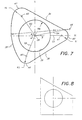
- One specific configuration of the blade mounting member has a center point with a horizontal and vertical axis therethrough.
- “in front of” the vertical axis means to the right of the vertical axis or in the positive horizontal direction, and “behind” the vertical axis means the opposite thereof; “above the horizontal” means on top of the horizontal axis or in the positive vertical diretion, and “below” the horizontal means the opposite thereof.
- a first corner of the triangle is located at a radius R1 which emanates from a point located a distance D1 away from the center point in front of the vertical and along the horizontal axis.
- a second corner is located at a radius R2 such that R2 approximately equals 1.2 R1, and emanates from a point located behind the vertical axis a distance D2 away from the center point and at an angle 0 of about 54 degrees above the horizontal axis.
- the distance D2 approximately equals .93 D1.
- a third corner of the triangle has a radius R3 such that R3 approximately equals 1.06 R1, and emanates from a point located behind the vertical axis a distance D3 away from the center point and at an angle a of about 66 degrees below the horizontal axis.
- the distance D3 approximately equals .89 D1.
- a first side of the triangle tangentially connects the outside of the first and second corners, and a second side tangentially connects the outside of said second and third corners.
- a third side having a radius R4 emanating from a pointed located in front of the vertical axis a distance D4 away from the center point and at an angle of about 9 degrees above the horizontal axis. D4 approximately equals 1.32 D1, where said third side tangentially connects the outside of said first and third corners.
- a method of orienting the rotating concrete cutting blade on the drive shaft in the correct orientation comprises providing a blade mounting member which is non-symmetrical when rotated 180 degrees about an axis orthogonal to the longitudinal axis of the drive shaft about which the blade rotates during cutting.
- a hole which is generally in the shape of a triangle or a trapezium, is provided in the blade, where the hole when viewed from the first side of the blade is the same as the shape of the blade mounting member, but not when viewed from the opposite side of the blade.
- the blade is then placed on the blade mounting member so that the hole in the blade coincides with and fits over the blade mounting member, and the blade is secured to the shaft.
- the blade is secured by placing a washer on the shaft distal of the blade, and then placing a nut on the threaded portion of the shaft whereby the nut provides a clamping force to clamp the blade between the washer and the flange of the sleeve.
- This method and apparatus prevents the user from attaching the rotating cutting blade to the arbor sleeve in an incorrect orientation.
- cutting blades used to cut wet or green concrete may not be mismounted so as to cut in the wrong direction and cause chipping and spalling, and will not overheat and warp, further causing damage to the concrete.
- the arbor sleeve of the present invention will also help prevent the use of a cutting blade which is not designed for use with a concrete saw which is fitted with this arbor. In this manner, users will be prevented from accidentally using a cutting blade which was not intended for use with the particular concrete saw.
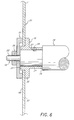
- FIGS. 1-3 and 6-7 there is shown the mounting of the present invention in the form of an arbor sleeve 10.
- the arbor sleeve 10 is for use with a saw, such as a concrete saw 12 having a motor 14.
- a drive shaft 16 is rotated by the motor 14 about the longitudinal axis of the shaft 16.
- the drive shaft 16 has a free end 18 for acceptance of a cutting blade 21.
- the free end 18 of the drive shaft 16 extends to a shoulder 19 with a smaller threaded shaft 20 extending longitudinally from the shoulder 19 away from the saw 12.
- a concrete cutting saw such as that described in U.S. Patent No.
- the drive shaft 16 is turned such that the blade 21 will cut in an up-cut direction, as shown relative to the direction of travel 27 of the saw 12.
- the arbor sleeve 10 has a proximal end 23 and a distal end 25 relative to the saw 12, with the proximal end 23 being closer to the saw 12 and the distal end 25 being further away.
- the arbor sleeve 10 also has a shaft mounting portion 22, a blade mounting member 24, and a central bore 26 therethrough.
- the shaft mounting portion 22 is generally cylindrical in shape, and is located at the proximal end 23 of the arbor sleeve 10.
- the shaft mounting portion 22 has an outer diameter of about .81 inches (20.6 mm) and a length of about .39 inches (9.9 mm). The length is primarily a function of the desired contact area between the drive shaft 16 and the arbor sleeve 10. The outer diameter is only slightly larger than the diameter of the shaft 16 upon which the arbor sleeve 10 is mounted.
- the shaft mounting portion 22 is the part of the arbor sleeve 10 which is used to connect the sleeve to the free end 18 of the drive shaft 16. The shaft mounting portion 22, as illustrated, is secured to the free end 18 of the drive shaft 16.
- the mounting portion 22 may be welded, or attached by screws, pins, friction or other means known to those skilled in the art so as to prevent rotation of arbor sleeve 10 relative to shaft 16.
- the shoulder 19 advantageously abuts with the distal end 23 of the sleeve.
- a blade support flange 30 extends radially outward from between the shaft mounting member 24 and the blade mounting member 26.
- the blade support flange 30 is also cylindrical in shape, but has a larger diameter than the mounting portion 22.
- the flange 30, as illustrated, has an outer diameter of about 1.5 inches (38.1 mm).
- the flange 30 has a thickness of about .22 inches (5.6 mm).
- the flange 30 is sized to prevent the cutting blade 21 from sliding past the blade mounting member 24 and along the drive shaft 16.
- the central bore 26 passes through the center of the flange 30 as well.
- the blade mounting member 24 contains a specially shaped mounting surface of the arbor sleeve 10.
- the blade mounting member 24, as illustrated, is generally triangular in shape, with three sides of unequally length and rounded corners. Advantageously, two of the sides are substantially straight while the third side is convex.
- the blade mounting member 24 thus has three sides 34, 36, 38, joined at three corners 40, 42, 44, and with the central bore 26 running therethrough.
- the mounting member 24 may be defined from a center point 28 located at the center of the bore 26 and an arbitrary horizontal axis H and vertical axis V running through this center point.
- the first corner 40 is, as illustrated, rounded, having a radius R1 of about .135 inches (3.4 mm), the radius extending from a first point 41 located in front of the vertical along the horizontal axis H (or at an angle of 0 degrees along the horizontal axis H) a distance D1 of about .487 inches (12.4 mm) from the center point 28.
- the second corner 42 is also rounded, having a radius R2 of about .163 inches (4.1 mm).
- the radius of the second corner 42 extends from a second point 43 located behind the vertical axis V, being a distance D2 of about .447 inches (11.4 mm) from the center point 28 and at an angle 0 of about 54 degrees above horizontal axis H.
- the third corner 44 is also rounded, having a radius R3 of about .143 inches (3.6 mm).
- the radius of the third corner 44 extends from a third point 45 located behind the vertical axis V, being about .432 inches (11.0 mm) from the center point 28 and at an angle a of about 66 degrees below the horizontal axis H.
- the first side 34 is substantially straight, and as illustrated, connects the first corner 40 and second corner 42 in a tangent fashion, thus having a length of about .830 inches (21.1 mm).
- the second side 36 is also generally straight, connecting the first corner 42 and third corner 44 in a tangential fashion, thus having a length of about .771 inches (1.96 mm).
- the third side 38 is arcuate in shape, having a radius R4 of about 1.095 inches (27.8 mm).
- the radius of the third side 38 extends from a fourth point 46 located in front of the vertical axis V, being a distance D4 of about .644 inches (16.4 mm) from the center point 28 and at an angle of about 9 degrees above the horizontal axis H.
- the third side 38 intersects the second corner 42 and third corner 44 in a tangential fashion.
- the central bore 26 has a radius of about .313 inches (7.9 mm), radiating about the center point 28.
- the shaft bore 26 may, of course, be a different diameter, depending on the diameter of the drive shaft 16 on which it is to be mounted.
- the dimensions of the blade mounting member 24 may be assigned as follows.
- the first corner 40 radius (R1 second corner 42 radius (R2) and third corner 44 radius (R3) have a relation such that R2 approximately equals 1.2 R1 and R3 approximately equals 1.06 R1.
- the distance from the center point 28 to the first point 41 (D1 second point 42 (D2) and third point 43 (D3) is such that D2 approximately equals .93 D1 and D3 approximately equals .89 D1 when the lines from the center point 28 to each point 41, 43, 45 are along about the same angle as defined above.
- the first side 36 and second side 34 are of such a length as to intersect the outside of corners 40, 42, 44 in a tangential fashion.
- the third side 38 is of such a radius as to intersect the outside of the second corner 42 and third corner 44 in a tangential fashion, when the fourth point 46 is along the angle defined above and a distance D4 of about 1.32 D1.
- the central bore 26 has a radius RB equal to about 2.32 times R1.
- blade mounting member 24 is generally triangular in shape, it is not symmetric. Scalene triangular shapes, where each side is a different length, are believed advantageous.
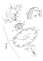
- the cutting blade 21 has a first distal side 48, second proximal side 50, and a mounting hole 52 therein.
- the mounting hole 52 is shaped so that when the cutting blade 21 is viewed from its distal side 48, the hole 52 has the same shape as the blade mounting member 24 and is only larger in size to the extent necessary to allow the blade to be positioned on the mounting member 24.
- a tolerance of about .002 to .003 inches (.05 to .08 mm) between the size of the hole 52 and mounting member 24 works well.
- the cutting blade 21 may be mounted on the blade mounting member 24 of arbor sleeve 10 as illustrated in FIG. 4.
- the blade 21 is secured by placing a washer 54 distally of the blade on the threaded end 20 of the drive shaft 16.
- the washer 54 is, as illustrated in FIG. 6, a metal disk having a hollow center section which faces the blade and a center hole to allow the passage of the smaller diameter threaded shaft 20 therethrough.
- a nut 56 is then positioned on the threaded smaller shaft 20 of the drive shaft 16 and tightened so as to press the blade 21 between the peripheral portion of washer 54 and the flange 30 of the arbor sleeve 10. As shown in FIG. 6, friction from the clamping force exerted by nut 56 prevents rotation of the sleeve 10 and blade 21.
- the sleeve 10 can be secured to shaft 16 as previously described.
- a set screw 55 is shown in phantom in FIG. 6 being inserted into hole 57 in shaft 16.
- the nut 56 and washer 54 could also be combined into one part rather than two separate pieces.
- the blade 21 may alternatively be secured by a threaded bolt 58 engaging a threaded hole 59.
- the drive shaft 16 does not have a threaded portion 20, and instead has the threaded hole 59 in its end along its longitudinal axis.
- the blade 21 is pressed between the flange 30 of the sleeve 10 and the washer 54 by the bolt 58 which is tightened into the hole 59 in the shaft 16.
- the washer 54 and the bolt 58 could be formed as one piece an operate in the same manner.
- the mounting hole 52 corresponds in shape to the blade mounting member 24 and will not be repeated in detail.
- the hole 52 is created by punching from the cutting blade 21 the mounting member 24 shape.
- the hole 52 could also be created by machining. It is to be understood that the dimensions detailed above for the sleeve 10 and for the hole 52 may be varied moderately and still achieve the same shapes and tolerances.
- the blade 21 can only be mounted upon the arbor sleeve 10 in one orientation.
- the cutting blade 21 is manufactured so that it will only cut properly if rotating in one specific direction.
- the cutting blade 21 is machined such that when the first side 48 faces away from the saw 12, the blade will cut in the correct up-cut direction.
- FIG. 5 if a user attempts to position the cutting blade 21 on the arbor sleeve 10 in a position where the second side 50 of the blade faces away from the saw 12, the blade 21 will not fit on the mounting member 24. This is because when the blade 21 is flipped over, the blade mounting member 24 and the hole 52 in the blade 21 have shapes that no longer coincide.
- This feature is provided by having the blade mounting member 28 of the arbor sleeve 10 and the mounting hole 52 in the cutting blade 21 be non-symmetrical, so that the mirror image of the hole 52 or member 24 is not the same as the shape of the hole 52 or member 24 viewed directly.
- any number of shapes for blade mounting member 24 are possible.
- the primary requirement in order to prevent mismounting is that the blade mounting member 28 and corresponding mounting hole 52 be of a non-symmetrical shape when viewed from opposite sides along the longitudinal axis, as illustrated by comparing FIGS. 4 & 5 where the blade 21 is rotated 180 degrees about vertical axis V (FIG. 7). This can be accomplished by the asymmetric triangular shape discussed above, but four or more sided figures will also work.
- an arbor or arbor sleeve with blade mounting member having a trapezium shape could work (FIG. 8).
- Such shapes need not necessarily have straight sides, as the mounting above does not.
- a three sided arbor or arbor sleeve 10 is preferred, however, because it reduces machining costs. Further, the fewer number of sides makes it easier for the user to mount the blade 21 on the sleeve 10, as there are fewer blade 21 and sleeve 10 positions which must be either visually or manually eliminated in order to find the correct alignment.
- the shape of the blade mounting member 24 may be machined directly on the end of the drive shaft 16 itself (not shown), instead of being formed on a sleeve 10 which is then secured to the shaft 16.
- an arbor or arbor sleeve 10 on the drive shaft 16 of a saw 12.
- the blade mounting member 24 of the arbor sleeve 10 has a mounting surface 24 shaped so that when viewed directly and in a mirror, the shapes cannot coincide.
- the mounting hole 52 in the cutting blade's 21 first side 48 has a shape which corresponds to that of the mounting member 24.
- the cutting blade 21 is pressed onto the mounting member 24 of the sleeve 10 with the first side 48 facing away from the saw 12, as is the only orientation in which the blade 21 will fit onto the sleeve 10.
- the washer 54 is then placed on the shaft 16 against the first side 48 of the blade 21, and the nut 56 is threaded onto the smaller portion of the shaft 20 to secure the blade 21 to the sleeve 10 between the washer 54 and the flange 30.
- the blade 21 may be secured by inserting the threaded bolt 58 into the hole 59 in the shaft 16 in order to press the blade 21 between the washer 54 and the flange 30, as was discussed above.
Landscapes
- Engineering & Computer Science (AREA)
- Mechanical Engineering (AREA)
- Life Sciences & Earth Sciences (AREA)
- Wood Science & Technology (AREA)
- Forests & Forestry (AREA)
- Mining & Mineral Resources (AREA)
- Processing Of Stones Or Stones Resemblance Materials (AREA)
- Polishing Bodies And Polishing Tools (AREA)
- Sawing (AREA)
- Nonmetal Cutting Devices (AREA)
- Structures Of Non-Positive Displacement Pumps (AREA)
- Milling Processes (AREA)
- Harvester Elements (AREA)
- Drilling Tools (AREA)
- Knives (AREA)
Claims (20)
Applications Claiming Priority (3)
| Application Number | Priority Date | Filing Date | Title |
|---|---|---|---|
| US07/863,708 US5303688A (en) | 1992-04-03 | 1992-04-03 | Mounting arbor for saw cutting blades |
| US863708 | 1992-04-03 | ||
| PCT/US1993/002968 WO1993019907A1 (en) | 1992-04-03 | 1993-03-31 | Mounting arbor for saw cutting blades |
Publications (3)
| Publication Number | Publication Date |
|---|---|
| EP0633830A1 EP0633830A1 (de) | 1995-01-18 |
| EP0633830B1 true EP0633830B1 (de) | 1995-11-15 |
| EP0633830B2 EP0633830B2 (de) | 2000-04-19 |
Family
ID=25341617
Family Applications (1)
| Application Number | Title | Priority Date | Filing Date |
|---|---|---|---|
| EP19930911566 Expired - Lifetime EP0633830B2 (de) | 1992-04-03 | 1993-03-31 | Spindel zum festspannen von kreissägeblättern |
Country Status (12)
| Country | Link |
|---|---|
| US (4) | US5303688A (de) |
| EP (1) | EP0633830B2 (de) |
| JP (1) | JP2829357B2 (de) |
| KR (1) | KR100295713B1 (de) |
| AT (1) | ATE130238T1 (de) |
| AU (1) | AU672199B2 (de) |
| CA (1) | CA2132195C (de) |
| DE (1) | DE69300824T3 (de) |
| DK (1) | DK0633830T4 (de) |
| ES (1) | ES2079978T5 (de) |
| HK (1) | HK40997A (de) |
| WO (1) | WO1993019907A1 (de) |
Families Citing this family (106)
| Publication number | Priority date | Publication date | Assignee | Title |
|---|---|---|---|---|
| US5303688A (en) * | 1992-04-03 | 1994-04-19 | Chiuminatta Edward R | Mounting arbor for saw cutting blades |
| US5477845A (en) * | 1994-08-12 | 1995-12-26 | Zuzelo; Edward A. | Saw blade and mounting means for the same |
| SE506537C2 (sv) * | 1995-04-05 | 1998-01-12 | Eriksson Ab A K | Sågaxel för flytande montering av ett antal sågklingor till följd av formlåsning samt en sågklinga att monteras på axel |
| US5799558A (en) * | 1996-03-06 | 1998-09-01 | Pacific Saw And Knife Company | Arbor and circular saw with asymmetric spline having generally radial force-transmitting face |
| US6230600B1 (en) | 1996-07-12 | 2001-05-15 | Precision Arbor Systems, Inc. | Saw arbor and guided circular saw |
| US5901629A (en) * | 1996-07-12 | 1999-05-11 | Precision Arbour Systems, Inc. | Saw arbor and guided circular saw |
| US6493934B2 (en) | 1996-11-12 | 2002-12-17 | Salman Akram | Method for sawing wafers employing multiple indexing techniques for multiple die dimensions |
| US6250192B1 (en) | 1996-11-12 | 2001-06-26 | Micron Technology, Inc. | Method for sawing wafers employing multiple indexing techniques for multiple die dimensions |
| USD390435S (en) | 1996-11-29 | 1998-02-10 | Sankyo Diamond Industrial Co., Ltd. | Diamond abrasive saw blade |
| US5950612A (en) * | 1997-10-20 | 1999-09-14 | Edward A. Zuzelo | Apparatus for cutting concrete |
| IT1299363B1 (it) | 1998-03-06 | 2000-03-16 | Lupi Quintilio | Sistema ad elementi componibili per lavorazone ad asportazione di materiali per marmo, pietra e simili |
| US6203416B1 (en) * | 1998-09-10 | 2001-03-20 | Atock Co., Ltd. | Outer-diameter blade, inner-diameter blade, core drill and processing machines using same ones |
| USD427042S (en) * | 1999-09-14 | 2000-06-27 | Black & Decker Inc. | Cutting tool hole |
| USD424076S (en) * | 1999-02-24 | 2000-05-02 | Black & Decker Inc. | Mounting device for a cutting tool |
| USD417598S (en) * | 1999-02-24 | 1999-12-14 | Black & Decker Inc. | Rotatable cutting tool |
| CA2290178A1 (en) * | 1999-03-08 | 2000-09-08 | Black & Decker Inc. | Saw blade and mounting device for the same |
| US6439091B1 (en) * | 1999-04-19 | 2002-08-27 | Black & Decker Inc. | Clutch mechanism |
| JP3440888B2 (ja) * | 1999-06-21 | 2003-08-25 | 株式会社村田製作所 | ダイシングブレード及び電子部品の製造方法 |
| US6340022B1 (en) | 1999-10-01 | 2002-01-22 | Daniel J. Schroer | Blade and arbor adaptor for circular saw |
| DE10040330A1 (de) * | 2000-08-17 | 2002-02-28 | Hilti Ag | Elektrowerkzeug mit Spanneinrichtung |
| US6945862B2 (en) * | 2000-12-07 | 2005-09-20 | C. & E. Fein Gmbh | Power tool having a receptacle for securing a tool |
| DE10061559A1 (de) | 2000-12-07 | 2002-06-13 | C & E Fein Gmbh & Co Kg | Aufnahme zur Befestigung eines Werkzeuges an einer Antriebswelle und Adapter hierzu |
| US20020185121A1 (en) * | 2001-06-06 | 2002-12-12 | Farnworth Warren M. | Group encapsulated dicing chuck |
| US20030044481A1 (en) * | 2001-08-28 | 2003-03-06 | Beaudry Wallace J. | Cast ceramic edge or embossed surface for a cutting die |
| US6682272B2 (en) * | 2001-10-12 | 2004-01-27 | B & J Manufacturing | Rubber cutting apparatus |
| DE20117159U1 (de) * | 2001-10-16 | 2002-02-14 | C. & E. Fein GmbH & Co KG, 70176 Stuttgart | Werkzeugmaschine mit Befestigungsflansch |
| US6729220B2 (en) * | 2001-11-30 | 2004-05-04 | Black & Decker Inc. | Spring loaded diamond arbor |
| US7287310B2 (en) * | 2003-02-06 | 2007-10-30 | Edward Zuzelo | Method of forming and attaching a blade that can receive both symmetrical and asymmetrical arbors |
| US6651644B1 (en) | 2003-02-06 | 2003-11-25 | Edward Zuzelo | Blade for circular saw having universal mounting hole for receiving a plurality of symmetrical and asymmetrical arbors |
| US20040244558A1 (en) * | 2003-06-05 | 2004-12-09 | Lowder Jeremy A. | Vibration dampener for a circular saw blade |
| US20050011329A1 (en) * | 2003-07-14 | 2005-01-20 | Briggs Edward L. | Circular saw blade mounting assembly |
| USD513952S1 (en) * | 2003-07-30 | 2006-01-31 | Ehwa Diamond Ind. Co., Ltd. | Saw blade |
| US20050229915A1 (en) * | 2004-04-14 | 2005-10-20 | Vangundy Jeffery R | Apparatus for cutting concrete using abrasive cable |
| DE102004027032B4 (de) * | 2004-06-02 | 2007-04-12 | MV Marketing und Vertriebs-GmbH & Co. KG Wieländer + Schill | Materialabtragendes Werkzeug sowie Verfahren zum Auftrennen von Schweißnähten |
| US20060185492A1 (en) * | 2005-02-18 | 2006-08-24 | Francois Chianese | Shoulder bushing for saw blades |
| US9216481B1 (en) | 2005-04-18 | 2015-12-22 | Edward A. Zuzelo | Method of producing a circular saw blade having reversible arbor mounting hole that receives an asymmetrical arbor |
| US7444914B2 (en) * | 2005-05-25 | 2008-11-04 | Saint-Gobain Abrasives Technology Company | Saw blade with multiple bore sizes |
| US7387563B2 (en) * | 2005-07-21 | 2008-06-17 | Robert Bosch Gmbh | Mandrel and accessory and related combination for use with a rotary tool |
| USD570175S1 (en) * | 2006-02-23 | 2008-06-03 | Bingham Everett D | Tool attachment |
| USD579297S1 (en) * | 2006-05-25 | 2008-10-28 | Robert Bosch Gmbh | Circular saw blade |
| US8549973B2 (en) * | 2006-07-24 | 2013-10-08 | Michael Patrick Burke | Rotating blade arbor hole |
| DE102006048315A1 (de) * | 2006-10-12 | 2008-04-17 | Robert Bosch Gmbh | Handwerkzeugmaschine, insbesondere elektrische Schere |
| DE102007018467A1 (de) | 2007-04-19 | 2008-10-23 | Robert Bosch Gmbh | Motorisch angetriebene Werkzeugmaschine |
| DE202008009525U1 (de) * | 2008-07-08 | 2009-11-19 | C. & E. Fein Gmbh | Werkzeug mit einer Befestigungsöffnung zur formschlüssigen Verbindung mit verschiedenen oszillierend antreibbaren Antriebswellen |
| JP2010116196A (ja) * | 2008-11-14 | 2010-05-27 | Nihon Tetra Pak Kk | シート状包装材料で被包した方形状包装物の切断開封装置 |
| USD609545S1 (en) * | 2009-02-03 | 2010-02-09 | Sanwa Kenma, Ltd. | Grindstone |
| US8425282B2 (en) * | 2009-10-15 | 2013-04-23 | PFERD Inc. | Accessory for power tool |
| USD623034S1 (en) | 2009-12-18 | 2010-09-07 | Techtronic Power Tools Technology Limited | Tool arbor |
| USD619152S1 (en) | 2009-12-18 | 2010-07-06 | Techtronic Power Tools Technology Limited | Adapter |
| GB2494004B8 (en) | 2010-01-26 | 2017-05-03 | Husqvarna Ab | A laying machine |
| US8925931B2 (en) | 2010-04-29 | 2015-01-06 | Black & Decker Inc. | Oscillating tool |
| US9073195B2 (en) | 2010-04-29 | 2015-07-07 | Black & Decker Inc. | Universal accessory for oscillating power tool |
| US9186770B2 (en) | 2010-04-29 | 2015-11-17 | Black & Decker Inc. | Oscillating tool attachment feature |
| US8616562B2 (en) | 2010-06-16 | 2013-12-31 | Robert Bosch Gmbh | Adapter for coupling an accessory tool to a drive member of a power tool |
| USD646540S1 (en) * | 2010-06-16 | 2011-10-11 | Robert Bosch Gmbh | Accessory tool adapter |
| USD646539S1 (en) * | 2010-06-16 | 2011-10-11 | Robert Bosch Gmbh | Accessory tool adapter |
| DE102010037109A1 (de) * | 2010-08-23 | 2012-02-23 | Bernhard Teufel | Messerscheibe zum Zerschneiden eines Materials |
| USD653523S1 (en) | 2010-09-29 | 2012-02-07 | Milwaukee Electric Tool Corporation | Adapter for a tool |
| USD651062S1 (en) | 2010-09-29 | 2011-12-27 | Milwaukee Electric Tool Corporation | Tool interface for an accessory |
| USD646542S1 (en) | 2010-09-29 | 2011-10-11 | Milwaukee Electric Tool Corporation | Accessory interface for a tool |
| US9149923B2 (en) | 2010-11-09 | 2015-10-06 | Black & Decker Inc. | Oscillating tools and accessories |
| IT1402777B1 (it) * | 2010-11-17 | 2013-09-18 | Ferrari & Cigarini S R L | Apparecchiatura per l'accoppiamento di un utensile rotante al relativo mandrino |
| USD638863S1 (en) * | 2010-11-19 | 2011-05-31 | Jae Hwan Huh | Grinding wheel blade |
| USD652274S1 (en) | 2010-12-14 | 2012-01-17 | Techtronic Power Tools Technology Limited | Universal interface for accessory blades |
| USD651877S1 (en) | 2010-12-14 | 2012-01-10 | Techtronic Power Tools Technology Limited | Universal interface for accessory blades |
| USD651876S1 (en) | 2010-12-14 | 2012-01-10 | Techtronic Power Tools Technology Limited | Universal interface for accessory blades |
| USD651878S1 (en) | 2010-12-14 | 2012-01-10 | Techtronic Power Tools Technology Limited | Universal interface for accessory blades |
| USD651875S1 (en) | 2010-12-14 | 2012-01-10 | Techtronic Power Tools Technology Limited | Universal interface for accessory blades |
| USD651874S1 (en) | 2010-12-14 | 2012-01-10 | Techtronic Power Tools Technology Limited | Universal interface for accessory blades |
| USD694598S1 (en) | 2012-06-25 | 2013-12-03 | Techtronic Power Tools Technology Limited | Universal interface for accessory blades |
| USD694599S1 (en) | 2012-06-25 | 2013-12-03 | Techtronic Power Tools Technology Limited | Universal interface for accessory blades |
| USD694596S1 (en) | 2012-06-25 | 2013-12-03 | Techtronic Power Tools Technology Limited | Universal interface for accessory blades |
| USD694597S1 (en) | 2012-06-25 | 2013-12-03 | Techtronic Power Tools Technology Limited | Universal interface for accessory blades |
| USD694076S1 (en) | 2012-06-25 | 2013-11-26 | Techtronic Power Tools Technology Limited | Universal interface for accessory blades |
| CN102717441A (zh) * | 2012-06-28 | 2012-10-10 | 福建南安市华天机械有限公司 | 一种低摩擦高锋利性金刚石刀头 |
| USD832666S1 (en) | 2012-07-16 | 2018-11-06 | Black & Decker Inc. | Oscillating saw blade |
| US9555554B2 (en) | 2013-05-06 | 2017-01-31 | Milwaukee Electric Tool Corporation | Oscillating multi-tool system |
| CN103640041B (zh) * | 2013-09-09 | 2016-02-10 | 宇宙纸巾技术有限公司 | 圆刀切割装置 |
| US9491997B2 (en) * | 2013-12-02 | 2016-11-15 | Soft Lines International, Ltd. | Drum assembly, cosmetic device with drum assembly, and battery compartment for cosmetic device |
| US20160319617A1 (en) * | 2015-04-28 | 2016-11-03 | Baker Hughes Incorporated | Casing Exit Mill Assemblies with Replaceable Blade Sleeve |
| US10113837B2 (en) | 2015-11-03 | 2018-10-30 | N2 Imaging Systems, LLC | Non-contact optical connections for firearm accessories |
| USD782261S1 (en) * | 2015-11-19 | 2017-03-28 | JPL Global, LLC | Arbor for cutting blades |
| US9956626B2 (en) * | 2016-03-05 | 2018-05-01 | Siruceo Dustless LLC | Dustless table saw |
| CN109891076B (zh) * | 2016-10-21 | 2021-05-18 | 本田技研工业株式会社 | 隔热插入部件及具备该隔热插入部件的发动机 |
| US10265778B2 (en) | 2017-01-16 | 2019-04-23 | Black & Decker Inc. | Accessories for oscillating power tools |
| USD814900S1 (en) | 2017-01-16 | 2018-04-10 | Black & Decker Inc. | Blade for oscillating power tools |
| JP2019069488A (ja) * | 2017-10-10 | 2019-05-09 | 株式会社オグラ | アダプターおよび切断装置 |
| US10753709B2 (en) | 2018-05-17 | 2020-08-25 | Sensors Unlimited, Inc. | Tactical rails, tactical rail systems, and firearm assemblies having tactical rails |
| CN108555386A (zh) * | 2018-06-22 | 2018-09-21 | 廊坊盛森磨具有限公司 | 一种装夹装置 |
| US10742913B2 (en) | 2018-08-08 | 2020-08-11 | N2 Imaging Systems, LLC | Shutterless calibration |
| US10921578B2 (en) | 2018-09-07 | 2021-02-16 | Sensors Unlimited, Inc. | Eyecups for optics |
| US11122698B2 (en) | 2018-11-06 | 2021-09-14 | N2 Imaging Systems, LLC | Low stress electronic board retainers and assemblies |
| US10801813B2 (en) | 2018-11-07 | 2020-10-13 | N2 Imaging Systems, LLC | Adjustable-power data rail on a digital weapon sight |
| US10796860B2 (en) | 2018-12-12 | 2020-10-06 | N2 Imaging Systems, LLC | Hermetically sealed over-molded button assembly |
| US11833598B2 (en) * | 2018-12-14 | 2023-12-05 | Fisher Controls International Llc | Stabilized cutting tool assemblies |
| US11143838B2 (en) | 2019-01-08 | 2021-10-12 | N2 Imaging Systems, LLC | Optical element retainers |
| US10693341B1 (en) * | 2019-02-08 | 2020-06-23 | N2 Imaging Systems, LLC | Motor hubs for shutter mechanisms |
| USD931069S1 (en) | 2019-05-03 | 2021-09-21 | Tti (Macao Commercial Offshore) Limited | Blade |
| USD882650S1 (en) * | 2019-08-16 | 2020-04-28 | Ali Industries, Inc. | Hex driver drum sander |
| USD880967S1 (en) | 2019-12-05 | 2020-04-14 | JPL Global, LLC | Arbor for cutting blades |
| JP7569868B2 (ja) * | 2020-06-25 | 2024-10-18 | フェスツール ゲーエムベーハー | ピボット・アセンブリ及びピボット・バイアス機構を備えた丸鋸 |
| US11738398B2 (en) | 2020-11-18 | 2023-08-29 | Milwaukee Electric Tool Corporation | Accessory for an oscillating power tool |
| CN112873294A (zh) * | 2021-03-24 | 2021-06-01 | 湖南华望科技股份有限公司 | 一种蜂窝纸板开槽用刀具 |
| USD1039009S1 (en) | 2022-02-25 | 2024-08-13 | Milwaukee Electric Tool Corporation | Early entry concrete saw |
| USD1102495S1 (en) | 2022-03-16 | 2025-11-18 | Techtronic Cordless Gp | Mandrel |
| USD1002319S1 (en) * | 2022-08-31 | 2023-10-24 | Procut Tool, Inc. | Diamond saw blade |
Family Cites Families (18)
| Publication number | Priority date | Publication date | Assignee | Title |
|---|---|---|---|---|
| US367211A (en) * | 1887-07-26 | ax-beet kimball | ||
| US1077572A (en) * | 1912-10-07 | 1913-11-04 | Edward L Chott | Dental-engine stone and mandrel. |
| US1130914A (en) * | 1914-04-28 | 1915-03-09 | John A Maker | Disk-holder. |
| US1947662A (en) * | 1933-02-20 | 1934-02-20 | Ind Of America Inc | Means for fastening wheels to spindles |
| US2572042A (en) * | 1948-07-13 | 1951-10-23 | Charles A Martin | Means for mounting cutting blades on shafts |
| US2649868A (en) * | 1951-07-05 | 1953-08-25 | Borg Warner | Mounting rotors on arbors of various transaxial contours |
| US2822648A (en) * | 1956-10-15 | 1958-02-11 | Super Cut | Rotary tool mounting and method of assembling the same |
| US2831514A (en) * | 1957-02-25 | 1958-04-22 | Avard Paul | Machine for slitting the bark of logs |
| US2912021A (en) * | 1958-03-10 | 1959-11-10 | Borg Warner | Mounting rotors on arbors of various transaxial contours |
| US2997819A (en) * | 1960-09-20 | 1961-08-29 | Norton Co | Abrasive disc |
| DE1878647U (de) * | 1963-04-30 | 1963-08-29 | Otto Baier | Verbindungsanordnung zwischen einer antriebswelle und einem kreissaegeblatt, insbesondere bei elektrohandsaegen. |
| US3869795A (en) * | 1973-06-20 | 1975-03-11 | Richards Mfg Co | Cutting blade for use with an oscillating cast cutter |
| US4454901A (en) * | 1979-04-02 | 1984-06-19 | Wilfred Thorsness | Multi-directional rotary saw |
| DE2941358A1 (de) * | 1979-10-12 | 1981-04-23 | Robert Bosch Gmbh, 7000 Stuttgart | Befestigungsvorrichtung fuer ein kreissaegeblatt auf einem antriebszapfen |
| US4267814A (en) * | 1979-12-06 | 1981-05-19 | Federal-Mogul Corporation | Abrasive saw blade for trapezoidal grooving |
| US4456303A (en) * | 1982-04-05 | 1984-06-26 | Due Joseph E | Machine and method for grooving pavement |
| US4928662B1 (en) * | 1986-03-25 | 1995-04-11 | Edward Chiuminatta | Skid plate for cutting unhardened concrete. |
| US5303688A (en) * | 1992-04-03 | 1994-04-19 | Chiuminatta Edward R | Mounting arbor for saw cutting blades |
-
1992
- 1992-04-03 US US07/863,708 patent/US5303688A/en not_active Expired - Lifetime
-
1993
- 1993-03-31 DK DK93911566T patent/DK0633830T4/da active
- 1993-03-31 DE DE69300824T patent/DE69300824T3/de not_active Expired - Lifetime
- 1993-03-31 CA CA 2132195 patent/CA2132195C/en not_active Expired - Lifetime
- 1993-03-31 EP EP19930911566 patent/EP0633830B2/de not_active Expired - Lifetime
- 1993-03-31 KR KR1019940703462A patent/KR100295713B1/ko not_active Expired - Fee Related
- 1993-03-31 AU AU40447/93A patent/AU672199B2/en not_active Expired
- 1993-03-31 JP JP51763493A patent/JP2829357B2/ja not_active Expired - Fee Related
- 1993-03-31 ES ES93911566T patent/ES2079978T5/es not_active Expired - Lifetime
- 1993-03-31 AT AT93911566T patent/ATE130238T1/de not_active IP Right Cessation
- 1993-03-31 WO PCT/US1993/002968 patent/WO1993019907A1/en not_active Ceased
-
1994
- 1994-01-25 US US08/186,030 patent/US5373834A/en not_active Expired - Lifetime
- 1994-11-16 US US08/340,614 patent/US5660161A/en not_active Expired - Lifetime
-
1995
- 1995-06-07 US US08/477,849 patent/US5603310A/en not_active Expired - Lifetime
-
1997
- 1997-04-03 HK HK40997A patent/HK40997A/en not_active IP Right Cessation
Also Published As
| Publication number | Publication date |
|---|---|
| AU672199B2 (en) | 1996-09-26 |
| KR100295713B1 (ko) | 2001-10-24 |
| AU4044793A (en) | 1993-11-08 |
| ES2079978T5 (es) | 2000-10-16 |
| JP2829357B2 (ja) | 1998-11-25 |
| EP0633830B2 (de) | 2000-04-19 |
| DK0633830T3 (da) | 1995-12-18 |
| US5373834A (en) | 1994-12-20 |
| WO1993019907A1 (en) | 1993-10-14 |
| US5660161A (en) | 1997-08-26 |
| EP0633830A1 (de) | 1995-01-18 |
| ES2079978T3 (es) | 1996-01-16 |
| US5303688A (en) | 1994-04-19 |
| JPH08501734A (ja) | 1996-02-27 |
| DE69300824T2 (de) | 1996-04-25 |
| DE69300824T3 (de) | 2001-01-11 |
| DE69300824D1 (de) | 1995-12-21 |
| CA2132195C (en) | 1999-01-19 |
| HK40997A (en) | 1997-04-11 |
| US5603310A (en) | 1997-02-18 |
| ATE130238T1 (de) | 1995-12-15 |
| DK0633830T4 (da) | 2000-09-25 |
| CA2132195A1 (en) | 1993-10-04 |
Similar Documents
| Publication | Publication Date | Title |
|---|---|---|
| EP0633830B1 (de) | Spindel zum festspannen von kreissägeblättern | |
| US5304018A (en) | Plunge cutting device and method for plastic pipe members such as pipe couplings, flanges, hubs, and the like | |
| US5477845A (en) | Saw blade and mounting means for the same | |
| US6439091B1 (en) | Clutch mechanism | |
| KR100274523B1 (ko) | 휴대식 구동 공구용 원반형 공구 비트 및 이 원반형 공구 비트를 장착한 휴대식 구동 공구 | |
| EP1034870A2 (de) | Sägeblatt und seine Montagevorrichtung | |
| US5951389A (en) | Drive system for small diameter abrasive discs | |
| US6079302A (en) | Saw and saw blade for simultaneously cutting and beveling | |
| FI89468B (fi) | Fastsaettningssystem foer delningsbett och kantningsfraes | |
| US20090156108A1 (en) | Hand-held power tool with locking nut | |
| US20050135886A1 (en) | Arbor arrangement | |
| AU3371995A (en) | Multi-handed milling cutter having indexable wedges and inserts | |
| US4507999A (en) | Saw retaining arrangement | |
| US6785971B2 (en) | Electric powered rotary hacksaw | |
| US4534687A (en) | Polymeric belt cutting apparatus | |
| US6799358B2 (en) | Method for assembling and disassembling cutting inserts | |
| US20050265795A1 (en) | Cutter head blade clamp | |
| US20040031475A1 (en) | Saw blade mounting arrangement | |
| JPH081491A (ja) | 面取り装置 | |
| US11504871B2 (en) | Shaft cutting tool | |
| US4496269A (en) | Polymeric belt cutting apparatus and method of making same | |
| US2755117A (en) | Machine tool spindles | |
| EP0995558A2 (de) | Kreisförmiges Schneidwerkzeug mit Auswechselbaren Klingen | |
| US4534102A (en) | Method of making polymeric belt cutting apparatus | |
| CA2388831A1 (en) | Insert drill with replaceable end cap |
Legal Events
| Date | Code | Title | Description |
|---|---|---|---|
| PUAI | Public reference made under article 153(3) epc to a published international application that has entered the european phase |
Free format text: ORIGINAL CODE: 0009012 |
|
| 17P | Request for examination filed |
Effective date: 19940914 |
|
| AK | Designated contracting states |
Kind code of ref document: A1 Designated state(s): AT BE CH DE DK ES FR GB GR IE IT LI LU MC NL PT SE |
|
| 17Q | First examination report despatched |
Effective date: 19950208 |
|
| GRAA | (expected) grant |
Free format text: ORIGINAL CODE: 0009210 |
|
| AK | Designated contracting states |
Kind code of ref document: B1 Designated state(s): AT BE CH DE DK ES FR GB GR IE IT LI LU MC NL PT SE |
|
| PG25 | Lapsed in a contracting state [announced via postgrant information from national office to epo] |
Ref country code: MC Free format text: LAPSE BECAUSE OF NON-PAYMENT OF DUE FEES Effective date: 19951115 Ref country code: GR Free format text: LAPSE BECAUSE OF FAILURE TO SUBMIT A TRANSLATION OF THE DESCRIPTION OR TO PAY THE FEE WITHIN THE PRESCRIBED TIME-LIMIT Effective date: 19951115 Ref country code: AT Effective date: 19951115 |
|
| REF | Corresponds to: |
Ref document number: 130238 Country of ref document: AT Date of ref document: 19951215 Kind code of ref document: T |
|
| REG | Reference to a national code |
Ref country code: IE Ref legal event code: FG4D Free format text: 66220 |
|
| REG | Reference to a national code |
Ref country code: DK Ref legal event code: T3 |
|
| REF | Corresponds to: |
Ref document number: 69300824 Country of ref document: DE Date of ref document: 19951221 |
|
| ITF | It: translation for a ep patent filed | ||
| REG | Reference to a national code |
Ref country code: ES Ref legal event code: FG2A Ref document number: 2079978 Country of ref document: ES Kind code of ref document: T3 |
|
| PG25 | Lapsed in a contracting state [announced via postgrant information from national office to epo] |
Ref country code: SE Effective date: 19960215 Ref country code: PT Effective date: 19960215 |
|
| REG | Reference to a national code |
Ref country code: CH Ref legal event code: NV Representative=s name: CABINET ROLAND NITHARDT CONSEILS EN PROPRIETE INDU |
|
| ET | Fr: translation filed | ||
| PG25 | Lapsed in a contracting state [announced via postgrant information from national office to epo] |
Ref country code: LU Free format text: LAPSE BECAUSE OF NON-PAYMENT OF DUE FEES Effective date: 19960331 Ref country code: IE Free format text: LAPSE BECAUSE OF NON-PAYMENT OF DUE FEES Effective date: 19960331 |
|
| PLBI | Opposition filed |
Free format text: ORIGINAL CODE: 0009260 |
|
| PLBF | Reply of patent proprietor to notice(s) of opposition |
Free format text: ORIGINAL CODE: EPIDOS OBSO |
|
| 26 | Opposition filed |
Opponent name: ROBERT BOSCH GMBH Effective date: 19960815 |
|
| NLR1 | Nl: opposition has been filed with the epo |
Opponent name: ROBERT BOSCH GMBH |
|
| PLBF | Reply of patent proprietor to notice(s) of opposition |
Free format text: ORIGINAL CODE: EPIDOS OBSO |
|
| PLAW | Interlocutory decision in opposition |
Free format text: ORIGINAL CODE: EPIDOS IDOP |
|
| RAP2 | Party data changed (patent owner data changed or rights of a patent transferred) |
Owner name: TRENT, ALAN, RAY Owner name: CHIUMINATTA, EDWARD R. |
|
| RIN2 | Information on inventor provided after grant (corrected) |
Free format text: CHIUMINATTA, EDWARD R. * TRENT, ALAN, RAY |
|
| PLAW | Interlocutory decision in opposition |
Free format text: ORIGINAL CODE: EPIDOS IDOP |
|
| RIN2 | Information on inventor provided after grant (corrected) |
Free format text: CHIUMINATTA, EDWARD R. * TRENT, ALAN RAY |
|
| RAP2 | Party data changed (patent owner data changed or rights of a patent transferred) |
Owner name: SOFF-CUT INTERNATIONAL INC. |
|
| NLT2 | Nl: modifications (of names), taken from the european patent patent bulletin |
Owner name: SOFF-CUT INTERNATIONAL INC. |
|
| PUAH | Patent maintained in amended form |
Free format text: ORIGINAL CODE: 0009272 |
|
| STAA | Information on the status of an ep patent application or granted ep patent |
Free format text: STATUS: PATENT MAINTAINED AS AMENDED |
|
| 27A | Patent maintained in amended form |
Effective date: 20000419 |
|
| AK | Designated contracting states |
Kind code of ref document: B2 Designated state(s): AT BE CH DE DK ES FR GB GR IE IT LI LU MC NL PT SE |
|
| REG | Reference to a national code |
Ref country code: CH Ref legal event code: AEN Free format text: MAINTIEN DU BREVET DONT L'ETENDUE A ETE MODIFIEE |
|
| NLR2 | Nl: decision of opposition | ||
| ITF | It: translation for a ep patent filed | ||
| ET3 | Fr: translation filed ** decision concerning opposition | ||
| NLR3 | Nl: receipt of modified translations in the netherlands language after an opposition procedure | ||
| REG | Reference to a national code |
Ref country code: CH Ref legal event code: PUE Owner name: CHIUMINATTA, EDWARD R.;CHIUMINATTA, ALAN, RAY -DAN |
|
| REG | Reference to a national code |
Ref country code: DK Ref legal event code: T4 |
|
| REG | Reference to a national code |
Ref country code: ES Ref legal event code: DC2A Kind code of ref document: T5 Effective date: 20000718 |
|
| NLS | Nl: assignments of ep-patents |
Owner name: SOFF-CUT INTERNATIONAL INC. |
|
| NLT1 | Nl: modifications of names registered in virtue of documents presented to the patent office pursuant to art. 16 a, paragraph 1 |
Owner name: EDWARD R. CHIUMINATTA;ALAN RAY TRENT |
|
| REG | Reference to a national code |
Ref country code: GB Ref legal event code: IF02 |
|
| PGFP | Annual fee paid to national office [announced via postgrant information from national office to epo] |
Ref country code: IT Payment date: 20060331 Year of fee payment: 14 |
|
| REG | Reference to a national code |
Ref country code: CH Ref legal event code: PCAR Free format text: CABINET ROLAND NITHARDT CONSEILS EN PROPRIETE INDUSTRIELLE S.A.;Y-PARC RUE GALILEE;1400 YVERDON-LES-BAINS (CH) |
|
| PG25 | Lapsed in a contracting state [announced via postgrant information from national office to epo] |
Ref country code: IT Free format text: LAPSE BECAUSE OF NON-PAYMENT OF DUE FEES Effective date: 20070331 |
|
| PGFP | Annual fee paid to national office [announced via postgrant information from national office to epo] |
Ref country code: ES Payment date: 20100319 Year of fee payment: 18 Ref country code: DK Payment date: 20100122 Year of fee payment: 18 Ref country code: CH Payment date: 20100131 Year of fee payment: 18 |
|
| PGFP | Annual fee paid to national office [announced via postgrant information from national office to epo] |
Ref country code: FR Payment date: 20100209 Year of fee payment: 18 |
|
| PGFP | Annual fee paid to national office [announced via postgrant information from national office to epo] |
Ref country code: GB Payment date: 20100115 Year of fee payment: 18 Ref country code: BE Payment date: 20100121 Year of fee payment: 18 |
|
| PGFP | Annual fee paid to national office [announced via postgrant information from national office to epo] |
Ref country code: DE Payment date: 20100121 Year of fee payment: 18 |
|
| BERE | Be: lapsed |
Owner name: *SOFF-CUT INTERNATIONAL INC. Effective date: 20110331 |
|
| REG | Reference to a national code |
Ref country code: NL Ref legal event code: V1 Effective date: 20111001 |
|
| REG | Reference to a national code |
Ref country code: CH Ref legal event code: PL Ref country code: DK Ref legal event code: EBP |
|
| GBPC | Gb: european patent ceased through non-payment of renewal fee |
Effective date: 20110331 |
|
| REG | Reference to a national code |
Ref country code: FR Ref legal event code: ST Effective date: 20111130 |
|
| PG25 | Lapsed in a contracting state [announced via postgrant information from national office to epo] |
Ref country code: BE Free format text: LAPSE BECAUSE OF NON-PAYMENT OF DUE FEES Effective date: 20110331 |
|
| PG25 | Lapsed in a contracting state [announced via postgrant information from national office to epo] |
Ref country code: DE Free format text: LAPSE BECAUSE OF NON-PAYMENT OF DUE FEES Effective date: 20111001 Ref country code: LI Free format text: LAPSE BECAUSE OF NON-PAYMENT OF DUE FEES Effective date: 20110331 Ref country code: FR Free format text: LAPSE BECAUSE OF NON-PAYMENT OF DUE FEES Effective date: 20110331 Ref country code: CH Free format text: LAPSE BECAUSE OF NON-PAYMENT OF DUE FEES Effective date: 20110331 Ref country code: NL Free format text: LAPSE BECAUSE OF NON-PAYMENT OF DUE FEES Effective date: 20111001 |
|
| REG | Reference to a national code |
Ref country code: DE Ref legal event code: R119 Ref document number: 69300824 Country of ref document: DE Effective date: 20111001 |
|
| PG25 | Lapsed in a contracting state [announced via postgrant information from national office to epo] |
Ref country code: GB Free format text: LAPSE BECAUSE OF NON-PAYMENT OF DUE FEES Effective date: 20110331 |
|
| REG | Reference to a national code |
Ref country code: ES Ref legal event code: FD2A Effective date: 20120424 |
|
| PG25 | Lapsed in a contracting state [announced via postgrant information from national office to epo] |
Ref country code: DK Free format text: LAPSE BECAUSE OF NON-PAYMENT OF DUE FEES Effective date: 20110331 |
|
| PG25 | Lapsed in a contracting state [announced via postgrant information from national office to epo] |
Ref country code: ES Free format text: LAPSE BECAUSE OF NON-PAYMENT OF DUE FEES Effective date: 20110401 |
|
| PGFP | Annual fee paid to national office [announced via postgrant information from national office to epo] |
Ref country code: NL Payment date: 20100331 Year of fee payment: 18 |