EP0633808B1 - Blood separation filter assembly and method - Google Patents
Blood separation filter assembly and method Download PDFInfo
- Publication number
- EP0633808B1 EP0633808B1 EP92915673A EP92915673A EP0633808B1 EP 0633808 B1 EP0633808 B1 EP 0633808B1 EP 92915673 A EP92915673 A EP 92915673A EP 92915673 A EP92915673 A EP 92915673A EP 0633808 B1 EP0633808 B1 EP 0633808B1
- Authority
- EP
- European Patent Office
- Prior art keywords
- filter
- well
- blood
- filter assembly
- serum
- Prior art date
- Legal status (The legal status is an assumption and is not a legal conclusion. Google has not performed a legal analysis and makes no representation as to the accuracy of the status listed.)
- Expired - Lifetime
Links
- 210000004369 blood Anatomy 0.000 title claims abstract description 68
- 239000008280 blood Substances 0.000 title claims abstract description 68
- 238000000926 separation method Methods 0.000 title claims abstract description 49
- 238000000034 method Methods 0.000 title claims abstract description 21
- 239000003365 glass fiber Substances 0.000 claims abstract description 58
- 239000000463 material Substances 0.000 claims abstract description 49
- 210000002966 serum Anatomy 0.000 claims abstract description 35
- 238000001914 filtration Methods 0.000 claims description 19
- 239000012491 analyte Substances 0.000 claims description 14
- 230000006835 compression Effects 0.000 claims description 9
- 238000007906 compression Methods 0.000 claims description 9
- 230000008569 process Effects 0.000 claims description 8
- 239000012530 fluid Substances 0.000 claims description 5
- 239000000126 substance Substances 0.000 claims description 5
- 239000005388 borosilicate glass Substances 0.000 claims description 2
- 230000000712 assembly Effects 0.000 abstract description 9
- 238000000429 assembly Methods 0.000 abstract description 9
- 239000000835 fiber Substances 0.000 abstract description 9
- 238000005119 centrifugation Methods 0.000 abstract description 3
- 239000010410 layer Substances 0.000 description 47
- 210000003743 erythrocyte Anatomy 0.000 description 25
- 238000002474 experimental method Methods 0.000 description 12
- 238000012360 testing method Methods 0.000 description 10
- 238000012856 packing Methods 0.000 description 9
- RZVAJINKPMORJF-UHFFFAOYSA-N Acetaminophen Chemical compound CC(=O)NC1=CC=C(O)C=C1 RZVAJINKPMORJF-UHFFFAOYSA-N 0.000 description 8
- HVYWMOMLDIMFJA-DPAQBDIFSA-N cholesterol Chemical compound C1C=C2C[C@@H](O)CC[C@]2(C)[C@@H]2[C@@H]1[C@@H]1CC[C@H]([C@H](C)CCCC(C)C)[C@@]1(C)CC2 HVYWMOMLDIMFJA-DPAQBDIFSA-N 0.000 description 8
- 238000011084 recovery Methods 0.000 description 8
- ZFXYFBGIUFBOJW-UHFFFAOYSA-N theophylline Chemical compound O=C1N(C)C(=O)N(C)C2=C1NC=N2 ZFXYFBGIUFBOJW-UHFFFAOYSA-N 0.000 description 8
- 239000003153 chemical reaction reagent Substances 0.000 description 7
- 150000002632 lipids Chemical class 0.000 description 6
- 239000000203 mixture Substances 0.000 description 6
- 102000003855 L-lactate dehydrogenase Human genes 0.000 description 5
- 108700023483 L-lactate dehydrogenases Proteins 0.000 description 5
- 238000002405 diagnostic procedure Methods 0.000 description 5
- WQZGKKKJIJFFOK-GASJEMHNSA-N Glucose Natural products OC[C@H]1OC(O)[C@H](O)[C@@H](O)[C@@H]1O WQZGKKKJIJFFOK-GASJEMHNSA-N 0.000 description 4
- 239000003146 anticoagulant agent Substances 0.000 description 4
- 229940127219 anticoagulant drug Drugs 0.000 description 4
- 235000012000 cholesterol Nutrition 0.000 description 4
- 239000011521 glass Substances 0.000 description 4
- 239000008103 glucose Substances 0.000 description 4
- 239000012528 membrane Substances 0.000 description 4
- 229960005489 paracetamol Drugs 0.000 description 4
- 229960000278 theophylline Drugs 0.000 description 4
- 102000004190 Enzymes Human genes 0.000 description 3
- 108090000790 Enzymes Proteins 0.000 description 3
- 230000008859 change Effects 0.000 description 3
- 229940079593 drug Drugs 0.000 description 3
- 239000003814 drug Substances 0.000 description 3
- 239000013618 particulate matter Substances 0.000 description 3
- 239000012466 permeate Substances 0.000 description 3
- 239000004033 plastic Substances 0.000 description 3
- 239000002390 adhesive tape Substances 0.000 description 2
- WQZGKKKJIJFFOK-VFUOTHLCSA-N beta-D-glucose Chemical compound OC[C@H]1O[C@@H](O)[C@H](O)[C@@H](O)[C@@H]1O WQZGKKKJIJFFOK-VFUOTHLCSA-N 0.000 description 2
- 210000004027 cell Anatomy 0.000 description 2
- 238000006243 chemical reaction Methods 0.000 description 2
- 230000000694 effects Effects 0.000 description 2
- 230000001788 irregular Effects 0.000 description 2
- 230000014759 maintenance of location Effects 0.000 description 2
- 238000005259 measurement Methods 0.000 description 2
- 239000002207 metabolite Substances 0.000 description 2
- 239000011148 porous material Substances 0.000 description 2
- 108090000623 proteins and genes Proteins 0.000 description 2
- 102000004169 proteins and genes Human genes 0.000 description 2
- WHBMMWSBFZVSSR-UHFFFAOYSA-N 3-hydroxybutyric acid Chemical compound CC(O)CC(O)=O WHBMMWSBFZVSSR-UHFFFAOYSA-N 0.000 description 1
- LTMHDMANZUZIPE-AMTYYWEZSA-N Digoxin Natural products O([C@H]1[C@H](C)O[C@H](O[C@@H]2C[C@@H]3[C@@](C)([C@@H]4[C@H]([C@]5(O)[C@](C)([C@H](O)C4)[C@H](C4=CC(=O)OC4)CC5)CC3)CC2)C[C@@H]1O)[C@H]1O[C@H](C)[C@@H](O[C@H]2O[C@@H](C)[C@H](O)[C@@H](O)C2)[C@@H](O)C1 LTMHDMANZUZIPE-AMTYYWEZSA-N 0.000 description 1
- 208000003870 Drug Overdose Diseases 0.000 description 1
- 206010033296 Overdoses Diseases 0.000 description 1
- 238000004458 analytical method Methods 0.000 description 1
- 238000010420 art technique Methods 0.000 description 1
- 238000003556 assay Methods 0.000 description 1
- 230000009286 beneficial effect Effects 0.000 description 1
- 210000000601 blood cell Anatomy 0.000 description 1
- 210000001124 body fluid Anatomy 0.000 description 1
- 239000010839 body fluid Substances 0.000 description 1
- 150000001875 compounds Chemical class 0.000 description 1
- 230000001419 dependent effect Effects 0.000 description 1
- LTMHDMANZUZIPE-PUGKRICDSA-N digoxin Chemical compound C1[C@H](O)[C@H](O)[C@@H](C)O[C@H]1O[C@@H]1[C@@H](C)O[C@@H](O[C@@H]2[C@H](O[C@@H](O[C@@H]3C[C@@H]4[C@]([C@@H]5[C@H]([C@]6(CC[C@@H]([C@@]6(C)[C@H](O)C5)C=5COC(=O)C=5)O)CC4)(C)CC3)C[C@@H]2O)C)C[C@@H]1O LTMHDMANZUZIPE-PUGKRICDSA-N 0.000 description 1
- 229960005156 digoxin Drugs 0.000 description 1
- LTMHDMANZUZIPE-UHFFFAOYSA-N digoxine Natural products C1C(O)C(O)C(C)OC1OC1C(C)OC(OC2C(OC(OC3CC4C(C5C(C6(CCC(C6(C)C(O)C5)C=5COC(=O)C=5)O)CC4)(C)CC3)CC2O)C)CC1O LTMHDMANZUZIPE-UHFFFAOYSA-N 0.000 description 1
- 201000010099 disease Diseases 0.000 description 1
- 208000037265 diseases, disorders, signs and symptoms Diseases 0.000 description 1
- 231100000725 drug overdose Toxicity 0.000 description 1
- 239000002657 fibrous material Substances 0.000 description 1
- 230000036541 health Effects 0.000 description 1
- 230000003862 health status Effects 0.000 description 1
- 239000004615 ingredient Substances 0.000 description 1
- 238000003780 insertion Methods 0.000 description 1
- 230000037431 insertion Effects 0.000 description 1
- 238000011835 investigation Methods 0.000 description 1
- 150000002605 large molecules Chemical class 0.000 description 1
- 210000000265 leukocyte Anatomy 0.000 description 1
- 229920002521 macromolecule Polymers 0.000 description 1
- 238000001471 micro-filtration Methods 0.000 description 1
- 239000004745 nonwoven fabric Substances 0.000 description 1
- 239000002245 particle Substances 0.000 description 1
- 239000000843 powder Substances 0.000 description 1
- 230000000979 retarding effect Effects 0.000 description 1
- YGSDEFSMJLZEOE-UHFFFAOYSA-M salicylate Chemical compound OC1=CC=CC=C1C([O-])=O YGSDEFSMJLZEOE-UHFFFAOYSA-M 0.000 description 1
- 229960001860 salicylate Drugs 0.000 description 1
- 239000002356 single layer Substances 0.000 description 1
- 150000003384 small molecules Chemical class 0.000 description 1
- 238000012800 visualization Methods 0.000 description 1
- 238000005406 washing Methods 0.000 description 1
- 238000009736 wetting Methods 0.000 description 1
Images


Classifications
-
- B—PERFORMING OPERATIONS; TRANSPORTING
- B01—PHYSICAL OR CHEMICAL PROCESSES OR APPARATUS IN GENERAL
- B01D—SEPARATION
- B01D39/00—Filtering material for liquid or gaseous fluids
- B01D39/14—Other self-supporting filtering material ; Other filtering material
- B01D39/20—Other self-supporting filtering material ; Other filtering material of inorganic material, e.g. asbestos paper, metallic filtering material of non-woven wires
- B01D39/2003—Glass or glassy material
- B01D39/2017—Glass or glassy material the material being filamentary or fibrous
-
- G—PHYSICS
- G01—MEASURING; TESTING
- G01N—INVESTIGATING OR ANALYSING MATERIALS BY DETERMINING THEIR CHEMICAL OR PHYSICAL PROPERTIES
- G01N33/00—Investigating or analysing materials by specific methods not covered by groups G01N1/00 - G01N31/00
- G01N33/48—Biological material, e.g. blood, urine; Haemocytometers
- G01N33/483—Physical analysis of biological material
- G01N33/487—Physical analysis of biological material of liquid biological material
- G01N33/49—Blood
- G01N33/491—Blood by separating the blood components
-
- Y—GENERAL TAGGING OF NEW TECHNOLOGICAL DEVELOPMENTS; GENERAL TAGGING OF CROSS-SECTIONAL TECHNOLOGIES SPANNING OVER SEVERAL SECTIONS OF THE IPC; TECHNICAL SUBJECTS COVERED BY FORMER USPC CROSS-REFERENCE ART COLLECTIONS [XRACs] AND DIGESTS
- Y10—TECHNICAL SUBJECTS COVERED BY FORMER USPC
- Y10T—TECHNICAL SUBJECTS COVERED BY FORMER US CLASSIFICATION
- Y10T436/00—Chemistry: analytical and immunological testing
- Y10T436/25—Chemistry: analytical and immunological testing including sample preparation
- Y10T436/25375—Liberation or purification of sample or separation of material from a sample [e.g., filtering, centrifuging, etc.]
Definitions
- This invention relates generally to filter assemblies according to the preamble of claim 1. Furtheron it refers to a clinical diagnostic device applying such filter material and to a process for separating fluids from particulate matter and particularly to the separation of plasma or serum from blood by filtration with such filter material.
- This invention is particularly directed to filtration assemblies using glass fibers under direct pressure resulting in compression of the glass fibers to specified densities. The high or positive pressure on the filter or filter layers is applied and maintained throughout the filtering process.
- Blood is used for diagnostic determinations or tests in order to provide information about the health status of patients.
- Blood is comprised mainly of corpuscular or particulate matter, for example, red and white blood cells and fluid matter such as serum or plasma.
- corpuscular or particulate matter for example, red and white blood cells and fluid matter such as serum or plasma.
- fluid matter such as serum or plasma.
- the patient's blood which has been transported to the laboratory is first separated from the serum (blood is allowed to clot with no anticoagulants present) or plasma (blood is drawn in the presence of anticoagulants) by centrifugation.
- the plasma or serum is used for the measurement of the particular analyte using automated instrumentation.
- This is a time-consuming process.
- tests or assays need to be performed which can yield results rapidly and at the patients' site. These urgent situations cannot be satisfactorily met with tests that need transportation, automated instrumentation or highly trained personnel. Therefore, the tests or devices which can be used for on-site testing with a rapid turn around time require a blood separation method which will permit the separation of serum or plasma from blood in less than 15 seconds and preferably in 2-10 seconds, will completely remove red blood cells, and will not be technique dependent, such as wiping or washing of red blood cells.
- the present invention provides filter assemblies according to the characterising part of claim 1, and the process of claim 4 to quickly separate plasma or serum from whole blood.
- the invention provides a fast (fifteen (15) seconds or less) and simple means for completely separating plasma or serum from whole blood, not just retarding, without the need of centrifugation.
- the present invention further serves for separating red blood cells from serum or plasma which is fast (in less than 15 seconds and preferably in 2 to 10 seconds) and in which the complete separation of serum from blood under these conditions does not affect the recovery of small molecules, such as glucose, lipid molecules, such as cholesterol, or large molecules, such as enzymes (Lactate dehydrogenase etc.).
- small molecules such as glucose, lipid molecules, such as cholesterol, or large molecules, such as enzymes (Lactate dehydrogenase etc.).
- glass fibers when it is desired to achieve separation of serum or plasma from blood, glass fibers produce the fastest flow rate when maintained in a compressed state under pressure. That is, a direct high positive pressure that produces or results in a high packing density of glass fibers which is higher than 0.5 gm/cm 3 , can be used to effectuate the fastest separation, i.e., in less than 15 seconds and preferably in 2 to 10 seconds.
- the high density of filter material instead of slowing down the rate of filtration, increases the rate of filtration of the fluid part from the particulate part, for example, of serum or plasma from red blood cells.
- the filtration is as effective when the filtering layer, which is under pressure, comprises at least two or more separate layers of glass fiber material instead of one layer of the same total thickness. That is, when two separate layers of glass fibers, as opposed to one comparable single layer, are placed one on top of the other under pressure, the different interfaces between the separate layers do not significantly affect the separation.
- a specific device and composition to carry out the processor method of the instant invention is also shown.
- the complete recovery of small and large molecular weight analytes including lipids utilizing the separation system of the instant invention is also demonstrated.
- the present invention may be used in any device having means of providing and maintaining positive pressure on the glass fibers themselves, such as described in US-A-5 104 619.
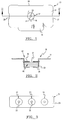
- FIG. 1 shows a separation filter assembly of this invention as a diagnostic card structure 10.
- the filter material 15 is shown contained in well structure 12 of a generally planar body 11.
- the card body 10 has alignment or positioning slots 19 and 20 and holding tab 18 to provide both for insertion of card 10 into an associated diagnostic meter for reading and for physical manipulation for observation, although these particular features are not essential for purposes of this invention.
- FIG. 3 shows the separation filter assembly as a diagnostic test strip 21 having planar body 25 with multiple well structures 22, 23 and 24. Any or all of these well structures may contain a filter material 15 for particular multiple testing purposes.
- FIG. 2 shows more detail of the filter assembly 15 of FIG. 1 and showing the cylindrical well wall 13 of well structure 12.
- the filter material 15 is shown sandwiched between the retaining cover structure 16 and the well bottom 14. Importantly, the filter material 15 is maintained compressed into the well structure 12 to provide the fast separation of serum or plasma from a blood sample, for example, introduced throughout central aperture 17.
- FIG. 4 shows a diagnostic test card 30 having centrally located raised cylindrical portion 35 with a well 36 within which the filter material 15 can be placed and held in a state of compression.
- the well 36 is positioned vertically with respect to top surface 33 which further has a perimeter lip 31 separated by a raised rib 32, although the last two mentioned features are not essential for the instant invention.
- the sectional view of FIG. 5 shows the cylindrical portion 35 having a folded lip 37, annular recess 38 and an upper horizontal shelf 39 which defines the well 36 as shown by well wall 40 and well bottom 41.
- the filter assembly 15 is contained within the well wall 40 and between the bottom upper surface 42 and a retaining structure, such as a snap fit cover 44 (FIGS. 7-9), cover 49 (FIGS. 10 and 11) or similar means which may be snapped within the annular recess 38 of card 30, for example.
- FIGS. 7-11 illustrate compression and retaining structures of the filter assemblies of the diagnostic card and strip wells.
- FIGS. 7-9 show a flat snap lid or cover 44 having a circular body 45, outer edge 46 and a central aperture 47 to receive the fluid or blood sample for separation.
- a grid structure 48 may span the aperture 47 to aid in compressingly engaging the filter material 15.
- FIGS. 10 and 11 show cylindrical cover 49 having outer circumferential lip 50, top portion 51 and aperture 52.
- Tapered side wall 53 is provided to snap into folded lip 37 and annular recess 38 with slightly different shape of that shown in FIG. 5 to, thereby, maintain the filter material 15 in a predetermined compressed state.
- FIG. 13 shows another means to compress and maintain a filter material for purposes of this invention.
- a well structure 55 has a body 56 with a well bottom 58 and cylindrical wall 57 having a number of interior adjustment ridges 62, 63 and 64 between which a retaining structure or cover 60 can be adjustably fixed to compressingly hold filter layers 65, 66 and reagent layer 67.
- a blood sample is introduced through aperture 61 and the test result is read through aperture 59, for example.
- another device could be used and made in the shape of a long rigid plastic strip on which the filter layer(s) and reactive layer are placed and compressed together by means of a strong adhesive tape to provide the positive pressure.
- FIG. 6 illustrates a filter material 15 having fiber filter layers 26 and 27. 28 designates a lower reagent impregnated layer, for example, to produce a measurable signal.
- various layer combinations including specific filter layer and reagent layers are usable to provide the filter assemblies and separation methods of this invention.
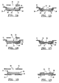
- FIG. 14 shows a filter assembly having only one filter layer 26 and a reagent impregnated layer 28 contained in well structure 70 of card structure 71.
- the impregnated layer 28 and the filter material 15 are placed on well bottom 72 and the filter layer 26 is shown in its uncompressed state.
- FIG. 15 shows the cover member 73 positioned in the well structure 70 whereby the filter layer 26 is held compressed by the cover member 73.
- FIG. 16 shows the filter assembly having two filter layers 68 and 69. As shown in Fig. 17, the positioning of the cover member 73 into the well shows the filter layers 68 and 69 being compressed. As further shown, the filter layers 69 and 69, when combined, have the same thickness as that of single filter layer 26.
- the wells or pockets of the above structures confine the fiber materials or glass fiber filter layers and associated matrices which contain reagents to produce measurably signals to indicate the presence of an analyte, for example.
- the rigid lids or covers 73 of the structures of FIGS. 14-17 are in direct contact with the filter material and are used to apply positive pressure and compression of the respective filter layers within the wells 70 to provide a higher packing density than the original or uncompressed material density. That is, in these devices the pressure on the glass fiber filters or membranes are applied and maintained by the rigid covers or lids 73 which are slapped into the respective wells 70 wherein the filter material is contained.
- the effective well depth for the compressed material is the space between the well bottom 72 and the snapped in top 73 regardless of the dimension of the well depth.
- the device can contain a lower reagent layer 28 to provide the necessary chemicals to react with the serum or plasma.
- a blood sample is introduced into aperture 76 and read at bottom aperture 77.
- FIG. 18 shows an alternate filter assembly where the filter material 15 is placed on top of a rigid base structure 74, such as a piece of rigid or semi-rigid plastic.
- FIG. 19 shows positive pressure applied to the filter material 15 by means of a strip of adhesive tape 75 which is shown to compress the filter layer 26 according to the teachings of this invention.
- the tape piece 75 has an aperture 78 for addition of a blood sample.
- the base structure 74 could be clear plastic so that any reaction can be visualized therethrough. Alternatively, an aperture may be provided in the base structure 74 for visualization or meter reading purposes. Any other devices or assemblies that can exert positive pressure and, therefore, compress the glass fibers into a higher packing density can be used to practice this invention.
- One important aspect of the invention is that separation of red blood cells from plasma can be accomplished in less than 15 seconds utilizing layers of glass fiber filter material with a small volume of blood, for example, 10-65 ⁇ l.
- the invention can be carried out by taking selected commercially available material(s) and modifying them sufficiently by pressure.
- many prior art or commercially available materials used for blood separation have proven not to be useful for the desired separation required and taught by this invention.
- the present invention allows the application of whole blood directly to the side of the device in contact with the glass fibers, and the fast observation, from the opposite side, of the reactions produced by the desired analyte present in the blood sample. Separation of the red cells is achieved mainly as a result of mechanical retention of particles.
- the irregular size and shape of the commercially available glass fibers it is not possible to determine or specify a defined pore size for such filters.
- glass fibers are often made of a high percent borosilicate glass and are composed of irregular filtering fibers typically varying in diameter between 0.1 ⁇ m and 7.0 ⁇ m.
- a key feature of the present invention is that the separation can be made independently of the diameters of the fibers provided that the positive pressure is high enough to compensate for low diameter fibers by increasing the packing density appropriately. For example, with some of the large diameter fibers a packing density of 0.60 gm/cm 3 can be successfully used, while with some of the small diameter fibers a packing density of 0.85 gm/cm 3 may be necessary to achieve the same separation. In all cases, a minimum depth of glass filters of 1 millimeter (0.04") was found desirable.
- a number of commercially available glass fiber filters or membranes can be utilized with the invention, but not all, to keep with the practical constraints of the invention, for example, sample size. Numerous glass fibers were tested for the purpose of this invention from various commercial sources as described in Table 1: Table 1 COMPANY FILTER NUMBER Millipore Corporation Bedford, Mass. AP-15, AP-20, AP-25, AP-40 Whatman, Inc.
- the device consists of a flat card containing a well 12 which has a diameter of 6.35 mm (0.25”) and a groove placed at a depth of 11.43 mm (0.45"). All the filter matrices or membranes used here were cut into 5.56 mm (0.219”) circles and were placed in the well. The bottom of the well has a hole of 3.96 mm (0.156”) to observe the change visually or to read the change with a reflectance meter.
- the lid or top 16 has a diameter of 6.35 mm (0.25"), a thickness of 0.76 mm (0.03”) and a hole of 3.96 mm (0.156”) which fits very tightly in the groove of the well.
- the control experiment was set up which consisted of placing one type of glass fibers layers, as shown in the following Table 2, with a total thickness or depth of 2.29 mm (0.09") on a Whatman 54 layer used as the reactive layer which has a thickness of about 0.127 mm (0.005"). No lid was placed in the device. Sixty-five (65) microliters ( ⁇ l) of freshly drawn blood was placed on the top of the glass fibers. A second experiment was performed with the same procedure as mentioned above except that the lid was placed in the groove located at the top of the well. As the effective well depth is only 1.143 mm (0.045”), the glass fibers, in the latter case, were compressed.
- Example 2 The material and methods of this example were the same as in Example 1 except that two different types of glass fibers were used to make up the total thickness of 2.29 mm (0.09") within the well. In one case, a combination of two S&S 24 and one S&S 30 were used. In the second case, a combination of one AP-25 and four AP-20 were used. The bottom layer was observed for time or speed (sec.) of wetting. The beneficial effect of positive pressure on the fastness of the separation when two types of glass fibers are used in combination, is demonstrated in Table 3. The observation for the presence or absence of RBC's was repeated after ten (10) minutes. In this example, the density of compressed material was 0.8-2.8 g/cm 3 .
- the thickness of the filtering materials was reduced to 1.52 mm (0.06").
- the device of Example 1 was used except that the effective well depth was different, i.e., the distance between the bottom of the lid when snapped in the groove and the bottom of the well was 1.0 mm (0.04").
- the glass fiber filter was a combination of one AP-25 and one AP-20 layer.
- Fifty-five microliters (55 ⁇ l) of freshly drawn blood was applied to the device with and without the lid and the time for separation was measured. Table 4 demonstrates that the speed of separation was further increased to 2-5 seconds. The observation to determine if blood cells came through was extended to ten (10) minutes.
- the diameter of the well in the device of FIG. 1 was reduced to 5.56 mm (0.219"). Therefore, the diameter of the filtering matrices was also reduced to 4.75 mm (0.187") circles.
- the effective depth of the well i.e., the distance between the snapped lid and the bottom of the well was 1.0 mm (0.04").
- Thirty microliters (30 ⁇ l) of freshly drawn blood was applied to the top glass fiber filters which was a combination of one AP-25 and one AP-20 filters and a reactive layer of Whatman 54 with and without the lid, and the time for separation was measured.
- Table 5 demonstrates that the speed of separation was the same as in Example 3 , i.e., 2-5 seconds in presence of the lid or under conditions of pressure. The observation to determine if red blood cells came through was extended to ten (10) minutes. The application of the lid increased the packing density by more than 30% in this configuration resulting in a compressed material density of about 0.6 gm/cm 3 . TABLE 5 Glass Fiber Configuration Time to Wet Bottom Pad Presence (+)/Absence (-) of RBCs One AP-25 and One AP-20 -with lid 2-5 seconds (-) -without lid > 30 seconds (+)
- Example 6 In another experiment utilizing the device dimensions of Example 3 , the following combination of glass fibers shown in Table 6, also showed separation times of less than ten (10) seconds when 55 ⁇ l of blood was applied to the surface of glass fibers and separated under positive pressure. In this experiment, the compression resulted in hither than 25% compression of glass fibers with a density of more than 0.5 gm/cm 3 .
- the instant invention achieves the complete separation or filtration of plasma or serum from blood with a seed of less than 15 seconds, preferably in 2-5 seconds, when positive or high pressure is applied.
- the glass fibers need to be compressed more than 25% of the original thickness or depth to produce a density of higher than 0.5 gm/cm 3 and need to have a minimum depth or thickness of 1 millimeter (0.04") in order to obtain complete separation.
- the extremely fast separation achieved is not a retardation of red blood cells as shown by the fact that even after ten (10) minutes no red blood cells came through. This process of separation can be achieved with any device similar to the ones shown in the drawing figures where positive pressure can be applied.
- Blood samples were obtained by drawing the patient's blood into glass Vacutainer, tubes. Blood samples were used for the analytical determination of metabolites such as Glucose, Cholesterol, and enzymes such as Lactate dehydrogenase.
- the blood samples used for the determination of other analytes and drugs such as B-hydroxybutyrate, acetaminophen or theophylline were spiked gravimetrically with the particular analyte under investigation. Part of each blood sample was centrifuged after letting it stand at room temperature for 20 minutes and serum was thus obtained. The serum was split into two aliquots for the following experiments.
- the device as described in Example 4 was used.
- the first serum aliquot 30 ⁇ l, was placed at the aperture of the cover of the device containing glass fiber filters, such combination of AP-25 and AP-20 (compressed by the snap fit cover), and a bottom reactive layer 28 which was impregnated with the necessary ingredients (i.e. chemicals known in the prior art which react with the particular analyte and which produce color proportionate to the concentration of analyte present in the sample) and dried at 50° for 5 minutes.
- the second serum aliquot was directly placed on the reactive layer of a second device which did not contain glass fiber filters. In both cases, the color produced in the reactive layer was measured as reflectance by a Macbeth reflectance meter at a fixed time. For each analyte, the reflectance value in both situations compared within 93-106% of each other.
- Example 4 an aliquot of the same whole blood, 30 ⁇ l, which was not centrifuged was placed on a third device, as described in Example 4 , consisting of glass filters such as a combination of AP-25 and AP-20 (compressed by a snap fit cover), and the same reactive bottom layer 28.
- the reflectance produced by the color at the bottom layer was compared with the reflectance value obtained in the first device where serum was used.
- Table 7 the analytes' recovery were 94-106% when blood was compared to serum irrespective of the molecular weight (from 113 to 140,000) of the chemical tested, or composition of the analyte (lipid or protein).
- a complete removal of RBCs was observed and the separation of serum from blood using glass fibers under positive pressure took place in 2-5 seconds.
Landscapes
- Life Sciences & Earth Sciences (AREA)
- Health & Medical Sciences (AREA)
- Engineering & Computer Science (AREA)
- Chemical & Material Sciences (AREA)
- Biomedical Technology (AREA)
- Hematology (AREA)
- Physics & Mathematics (AREA)
- Medicinal Chemistry (AREA)
- Biochemistry (AREA)
- Urology & Nephrology (AREA)
- Ecology (AREA)
- Food Science & Technology (AREA)
- Biophysics (AREA)
- Analytical Chemistry (AREA)
- Molecular Biology (AREA)
- General Health & Medical Sciences (AREA)
- General Physics & Mathematics (AREA)
- Immunology (AREA)
- Pathology (AREA)
- Geology (AREA)
- Chemical Kinetics & Catalysis (AREA)
- Investigating Or Analysing Biological Materials (AREA)
- Lubricants (AREA)
Abstract
Description
- This invention relates generally to filter assemblies according to the preamble of claim 1. Furtheron it refers to a clinical diagnostic device applying such filter material and to a process for separating fluids from particulate matter and particularly to the separation of plasma or serum from blood by filtration with such filter material. This invention is particularly directed to filtration assemblies using glass fibers under direct pressure resulting in compression of the glass fibers to specified densities. The high or positive pressure on the filter or filter layers is applied and maintained throughout the filtering process.
- Compounds associated with diseases or health conditions such as metabolites or drugs are often found in body fluids such as blood. Therefore, in clinical laboratories, blood is used for diagnostic determinations or tests in order to provide information about the health status of patients. Blood is comprised mainly of corpuscular or particulate matter, for example, red and white blood cells and fluid matter such as serum or plasma. Generally, in clinical laboratories, when a test for a particular blood analyte is needed, the patient's blood which has been transported to the laboratory, is first separated from the serum (blood is allowed to clot with no anticoagulants present) or plasma (blood is drawn in the presence of anticoagulants) by centrifugation. Subsequently, the plasma or serum is used for the measurement of the particular analyte using automated instrumentation. This is a time-consuming process. However, when an urgent or emergency situation arises, tests or assays need to be performed which can yield results rapidly and at the patients' site. These urgent situations cannot be satisfactorily met with tests that need transportation, automated instrumentation or highly trained personnel. Therefore, the tests or devices which can be used for on-site testing with a rapid turn around time require a blood separation method which will permit the separation of serum or plasma from blood in less than 15 seconds and preferably in 2-10 seconds, will completely remove red blood cells, and will not be technique dependent, such as wiping or washing of red blood cells.
- A number of techniques have been devised to accomplish this difficult separation. All techniques utilize a filtering step capable of separating red blood cells. Numerous materials have been used in the past as filters utilizing certain conditions, composition, and devices. Papers, non-woven fabrics, sheet-like filter material composed of powders or fibers such as man-made fibers or glass fibers and membrane filters having suitable pore sizes have been proposed. Although glass fibers have been known in the prior art as a material used for this separation process, subsequent improvements utilizing several specific methods have been claimed to give different degrees of speed and/or completion of separation. For example, Moyer et al. uses glass fibers for filtration of blood as described in U.S. patent No. 3,791,933. U.S. Patent No. 4,256,693 to Kondo et al. discloses a number of filter materials, including glass fibers, in a multi-layered integral chemical analysis element for use in blood separation. Subsequently, Vogel et al., U.S. Patent No. 4,477,575, showed a composition and process for allowing the separation of serum from whole blood consisting of glass fibers having an average diameter of 0.2 µm to 5 µm and a density of 0.1 gm/cm3 to 0.5 gm/cm3 without applying any positive pressure and which generally takes 1 to 5 minutes for separation of plasma from blood. Subsequently, Hillman et al., in U.S. Patent No. 4,753,776, showed a blood separation device using glass fibers to separate plasma from blood where the filtration is carried out at low pressures. The filter in this latter invention only retards the flow of red blood cells. However, these prior art techniques are not suitable where faster flow rates, for example, in less than 15 seconds and preferably in 2-10 seconds, are desired as well as the complete retention of the cells, i.e., determination of analytes needed for urgent care drug overdose cases, such as acetaminophen, theophylline, digoxin, salicylate, etc. Despite the need for assemblies and methods to quickly separate plasma or serum from whole blood, and which overcome the limitations and problems of the prior art, none insofar as is known has been proposed or developed.
- Accordingly, it is an object of the present invention to provide assemblies and methods to further refine and advance blood separation techniques.
- To achieve this object the present invention provides filter assemblies according to the characterising part of claim 1, and the process of claim 4 to quickly separate plasma or serum from whole blood. The invention provides a fast (fifteen (15) seconds or less) and simple means for completely separating plasma or serum from whole blood, not just retarding, without the need of centrifugation.
- The present invention further serves for separating red blood cells from serum or plasma which is fast (in less than 15 seconds and preferably in 2 to 10 seconds) and in which the complete separation of serum from blood under these conditions does not affect the recovery of small molecules, such as glucose, lipid molecules, such as cholesterol, or large molecules, such as enzymes (Lactate dehydrogenase etc.).
- In this invention it has surprisingly been found that when it is desired to achieve separation of serum or plasma from blood, glass fibers produce the fastest flow rate when maintained in a compressed state under pressure. That is, a direct high positive pressure that produces or results in a high packing density of glass fibers which is higher than 0.5 gm/cm3, can be used to effectuate the fastest separation, i.e., in less than 15 seconds and preferably in 2 to 10 seconds. Unexpectedly, the high density of filter material, instead of slowing down the rate of filtration, increases the rate of filtration of the fluid part from the particulate part, for example, of serum or plasma from red blood cells. To effectuate complete filtration of the particulate matter under these conditions, one can use a depth of filter material of 1,0 mm (0.04") or higher, while the diameter of glass filter material can vary. To attain such fast and complete separation, one must change the characteristics of commercially available material by applying significant pressure to achieve a resultant significant compression.
- Furthermore, the filtration is as effective when the filtering layer, which is under pressure, comprises at least two or more separate layers of glass fiber material instead of one layer of the same total thickness. That is, when two separate layers of glass fibers, as opposed to one comparable single layer, are placed one on top of the other under pressure, the different interfaces between the separate layers do not significantly affect the separation.
- A specific device and composition to carry out the processor method of the instant invention is also shown. The complete recovery of small and large molecular weight analytes including lipids utilizing the separation system of the instant invention is also demonstrated.
- These and other benefits of this invention will become clear from the following description by reference to the drawings.
-
- FIG. 1 is a top view of a diagnostic test card having a well structure having the filter assembly of this invention;
- FIG. 2 is a sectional view taken along line 2-2 of FIG. 1;
- FIG. 3 is a top view of a diagnostic test strip having a plurality of well structures;
- FIG. 4 is a top view of a diagnostic test card having another well structure embodiment having the filter assembly of this invention;
- FIG. 5 is a sectional view taken along line 5-5 of FIG. 4;
- FIG. 6 is a perspective view of a filter layer structure of this invention;
- FIG. 7 is a top view of a cover structure for use in the well structures of diagnostic cards and strips to contain the filter layers of this invention;
- FIG. 8 is a lateral view of the cover structure of FIG. 7;
- FIG. 9 is a top view of another cover structure for use in this invention;
- FIG. 10 is a top view of another cover structure for use in this invention;
- FIG. 11 is a sectional view taken along line 11-11 of FIG. 10;
- FIG. 12 is a sectional view of another well structure designed to fit the cover shown in FIGS. 10 and 11.
- FIG. 13 is a sectional view of another well structure for containing the filter assembly of this invention;
- FIG. 14 is a sectional view of an uncompressed filter assembly placed in a well structure,
- FIG. 15 is a sectional view of the filter assembly of Fig. 14 held compressed in the well structure;
- FIG. 16 is a sectional view of another uncompressed filter assembly placed in a well structure;
- FIG. 17 is a sectional view of the filter assembly of FIG. 16 held compressed in the well structure;
- FIG. 18 is a sectional view of a filter assembly placed on a base structure; and
- FIG. 19 is a sectional view of the filter assembly of FIG. 18 held compressed onto the base structure according to the teachings of this invention.
- The present invention may be used in any device having means of providing and maintaining positive pressure on the glass fibers themselves, such as described in US-A-5 104 619.
- For example, FIG. 1 shows a separation filter assembly of this invention as a
diagnostic card structure 10. Thefilter material 15 is shown contained inwell structure 12 of a generallyplanar body 11. Thecard body 10 has alignment orpositioning slots tab 18 to provide both for insertion ofcard 10 into an associated diagnostic meter for reading and for physical manipulation for observation, although these particular features are not essential for purposes of this invention. FIG. 3 shows the separation filter assembly as adiagnostic test strip 21 havingplanar body 25 with multiplewell structures filter material 15 for particular multiple testing purposes. - FIG. 2 shows more detail of the
filter assembly 15 of FIG. 1 and showing thecylindrical well wall 13 ofwell structure 12. Thefilter material 15 is shown sandwiched between the retainingcover structure 16 and the well bottom 14. Importantly, thefilter material 15 is maintained compressed into thewell structure 12 to provide the fast separation of serum or plasma from a blood sample, for example, introduced throughoutcentral aperture 17. - FIG. 4 shows a
diagnostic test card 30 having centrally located raisedcylindrical portion 35 with a well 36 within which thefilter material 15 can be placed and held in a state of compression. The well 36 is positioned vertically with respect totop surface 33 which further has aperimeter lip 31 separated by a raisedrib 32, although the last two mentioned features are not essential for the instant invention. The sectional view of FIG. 5 shows thecylindrical portion 35 having a foldedlip 37,annular recess 38 and an upperhorizontal shelf 39 which defines the well 36 as shown bywell wall 40 and well bottom 41. Thefilter assembly 15 is contained within thewell wall 40 and between the bottomupper surface 42 and a retaining structure, such as a snap fit cover 44 (FIGS. 7-9), cover 49 (FIGS. 10 and 11) or similar means which may be snapped within theannular recess 38 ofcard 30, for example. - FIGS. 7-11 illustrate compression and retaining structures of the filter assemblies of the diagnostic card and strip wells. FIGS. 7-9 show a flat snap lid or cover 44 having a
circular body 45,outer edge 46 and acentral aperture 47 to receive the fluid or blood sample for separation. Agrid structure 48 may span theaperture 47 to aid in compressingly engaging thefilter material 15. A different configuration of lid or cover, which is not flat, is shown in FIGS. 10 and 11, showingcylindrical cover 49 having outercircumferential lip 50,top portion 51 andaperture 52.Tapered side wall 53 is provided to snap into foldedlip 37 andannular recess 38 with slightly different shape of that shown in FIG. 5 to, thereby, maintain thefilter material 15 in a predetermined compressed state. A slightly different shape of the well havingannular ridge 54 and associatedlid 49 are shown in FIG. 12. FIG. 13 shows another means to compress and maintain a filter material for purposes of this invention. Awell structure 55 has abody 56 with a well bottom 58 andcylindrical wall 57 having a number ofinterior adjustment ridges hold filter layers reagent layer 67. A blood sample is introduced throughaperture 61 and the test result is read throughaperture 59, for example. Alternatively, another device could be used and made in the shape of a long rigid plastic strip on which the filter layer(s) and reactive layer are placed and compressed together by means of a strong adhesive tape to provide the positive pressure. - The filter assembly compositions and arrangement will be described with further particularity, in the Tables and examples set forth hereafter. However, FIG. 6 illustrates a
filter material 15 having fiber filter layers 26 and 27. 28 designates a lower reagent impregnated layer, for example, to produce a measurable signal. As will be discussed, various layer combinations including specific filter layer and reagent layers are usable to provide the filter assemblies and separation methods of this invention. - FIG. 14 shows a filter assembly having only one
filter layer 26 and a reagent impregnatedlayer 28 contained inwell structure 70 ofcard structure 71. The impregnatedlayer 28 and thefilter material 15 are placed on well bottom 72 and thefilter layer 26 is shown in its uncompressed state. FIG. 15 shows thecover member 73 positioned in thewell structure 70 whereby thefilter layer 26 is held compressed by thecover member 73. FIG. 16 shows the filter assembly having twofilter layers cover member 73 into the well shows the filter layers 68 and 69 being compressed. As further shown, the filter layers 69 and 69, when combined, have the same thickness as that ofsingle filter layer 26. - In summary, the wells or pockets of the above structures confine the fiber materials or glass fiber filter layers and associated matrices which contain reagents to produce measurably signals to indicate the presence of an analyte, for example. The rigid lids or covers 73 of the structures of FIGS. 14-17 are in direct contact with the filter material and are used to apply positive pressure and compression of the respective filter layers within the
wells 70 to provide a higher packing density than the original or uncompressed material density. That is, in these devices the pressure on the glass fiber filters or membranes are applied and maintained by the rigid covers orlids 73 which are slapped into therespective wells 70 wherein the filter material is contained. Thus, when thelid 73 is snapped into the well groove, the effective well depth for the compressed material is the space between the well bottom 72 and the snapped in top 73 regardless of the dimension of the well depth. As shown, the device can contain alower reagent layer 28 to provide the necessary chemicals to react with the serum or plasma. In use, a blood sample is introduced intoaperture 76 and read atbottom aperture 77. - FIG. 18 shows an alternate filter assembly where the
filter material 15 is placed on top of arigid base structure 74, such as a piece of rigid or semi-rigid plastic. FIG. 19 shows positive pressure applied to thefilter material 15 by means of a strip ofadhesive tape 75 which is shown to compress thefilter layer 26 according to the teachings of this invention. Thetape piece 75 has anaperture 78 for addition of a blood sample. Thebase structure 74 could be clear plastic so that any reaction can be visualized therethrough. Alternatively, an aperture may be provided in thebase structure 74 for visualization or meter reading purposes. Any other devices or assemblies that can exert positive pressure and, therefore, compress the glass fibers into a higher packing density can be used to practice this invention. - One important aspect of the invention is that separation of red blood cells from plasma can be accomplished in less than 15 seconds utilizing layers of glass fiber filter material with a small volume of blood, for example, 10-65 µl. The invention can be carried out by taking selected commercially available material(s) and modifying them sufficiently by pressure. However, many prior art or commercially available materials used for blood separation have proven not to be useful for the desired separation required and taught by this invention. The present invention allows the application of whole blood directly to the side of the device in contact with the glass fibers, and the fast observation, from the opposite side, of the reactions produced by the desired analyte present in the blood sample. Separation of the red cells is achieved mainly as a result of mechanical retention of particles. However, because of the irregular size and shape of the commercially available glass fibers, it is not possible to determine or specify a defined pore size for such filters.
- Commercially available glass fibers are often made of a high percent borosilicate glass and are composed of irregular filtering fibers typically varying in diameter between 0.1 µm and 7.0 µm. A key feature of the present invention is that the separation can be made independently of the diameters of the fibers provided that the positive pressure is high enough to compensate for low diameter fibers by increasing the packing density appropriately. For example, with some of the large diameter fibers a packing density of 0.60 gm/cm3 can be successfully used, while with some of the small diameter fibers a packing density of 0.85 gm/cm3 may be necessary to achieve the same separation. In all cases, a minimum depth of glass filters of 1 millimeter (0.04") was found desirable.
- A number of commercially available glass fiber filters or membranes can be utilized with the invention, but not all, to keep with the practical constraints of the invention, for example, sample size. Numerous glass fibers were tested for the purpose of this invention from various commercial sources as described in Table 1:
Table 1 COMPANY FILTER NUMBER Millipore Corporation Bedford, Mass. AP-15, AP-20, AP-25, AP-40 Whatman, Inc. GF/C, GF/B, GF/D, GF/F, 934-H Clifford, NJ PD 00823B143, PD813C120 PD 00812c53, PD008-11 Ahlstrom (Mount Holly Springs, PA) AHLSTROM 153, AHLSTROM 113 Schliecher & Schuell (Keene, NH) S&S 24,S&S 30, S&S 20 (3362)S&S 25Microfiltration Systems (MFS) (Dublin, CA) GA-200, GB-100R, GC-90 Hollingsworth & Vost Last Wapole, MA HB-5342, BG-08805 Eaton Dikeman (now Ahlstrom) Carlisle, PA 111, 121, 131, 141, 151, & 161 Mechery & Nagel Duren, W.G. 85/90F - These glass fiber filters were tested individually, and in combination with one another, for their ability to effect the separation of serum or plasma from blood. For most of the examples the devices shown in FIGS. 1, 4 and 19 were used. However, the devices of FIGS. 1 and 4 can produce more consistent pressure on the glass fiber layers and are easier to use. The effectiveness of positive pressure, which increases the packing density of glass fibers to higher than 0.5 gm/cm3, in producing better and faster separation of blood by using one or more glass fiber layers is clearly demonstrated in Examples 1-5. Analytical recovery section further demonstrates that using the device and the method of the instant invention, complete recovery of analytes with vastly different molecular weights or lipid composition can be achieved.
- The importance of positive high pressure provided on glass fibers in altering the speed of filtration of serum or plasma from whole blood and the complete removal of Red Blood Cells (RBC) is clearly demonstrated in this example.
- In this experiment, a device as shown in FIG. 1 was used. The device consists of a flat card containing a well 12 which has a diameter of 6.35 mm (0.25") and a groove placed at a depth of 11.43 mm (0.45"). All the filter matrices or membranes used here were cut into 5.56 mm (0.219") circles and were placed in the well. The bottom of the well has a hole of 3.96 mm (0.156") to observe the change visually or to read the change with a reflectance meter. The lid or top 16 has a diameter of 6.35 mm (0.25"), a thickness of 0.76 mm (0.03") and a hole of 3.96 mm (0.156") which fits very tightly in the groove of the well.
- To test the effect of positive pressure in removal of RBC's from serum, the following experiment was performed. The control experiment was set up which consisted of placing one type of glass fibers layers, as shown in the following Table 2, with a total thickness or depth of 2.29 mm (0.09") on a Whatman 54 layer used as the reactive layer which has a thickness of about 0.127 mm (0.005"). No lid was placed in the device. Sixty-five (65) microliters (µl) of freshly drawn blood was placed on the top of the glass fibers. A second experiment was performed with the same procedure as mentioned above except that the lid was placed in the groove located at the top of the well. As the effective well depth is only 1.143 mm (0.045"), the glass fibers, in the latter case, were compressed. Sixty-five (65) µl of freshly drawn blood was also applied. The appearance of serum on Whatman 54 paper was observed visually as indicated by complete wetness of Whatman 54 paper. The Whatman paper was additionally observed for the appearance of red blood cells. This layer was, furthermore, monitored several minutes to assure that the red blood cells were not just retarded. Table 2, column 1, describes various glass fibers used in this experiment with a total thickness of 2.29 mm (0.09"). To obtain this total thickness, two layers of AP-25 (Millipore Co.), each of 1.143 mm (0.045") thickness, were used and nine layers of AP-20 (Millipore Co.), each of 0.25 mm (0.01"), were used.
Column 2 shows the time required to wet the bottom pad. Column 3 describes either the presence of RBC's observed on Whatman 54 paper by (+) sign, or complete absence of RBC's observed by (-) sign, immediately, as well as the the end of ten (10) minutes. In this example, the density of compressed material was in the range of 0.7-4.0 gm/cm3.TABLE 2 Glass Fiber Configuration Time to Wet Bottom Pad Presence (+)/Absence (-) of RBCs AP-25 -with lid 11-13 seconds (-) -without lid >360 seconds (-) AP-20 -with lid 255 seconds (-) -without lid Did not permeate at all The results obtained were the same when whole blood in the presence of anticoagulant was used. - The material and methods of this example were the same as in Example 1 except that two different types of glass fibers were used to make up the total thickness of 2.29 mm (0.09") within the well. In one case, a combination of two
S&S 24 and oneS&S 30 were used. In the second case, a combination of one AP-25 and four AP-20 were used. The bottom layer was observed for time or speed (sec.) of wetting. The beneficial effect of positive pressure on the fastness of the separation when two types of glass fibers are used in combination, is demonstrated in Table 3. The observation for the presence or absence of RBC's was repeated after ten (10) minutes. In this example, the density of compressed material was 0.8-2.8 g/cm3.TABLE 3 Glass Fiber Configuration Time to Wet Bottom Pad Presence (+)/Absence (-) of RBCs Two S&S 24 and One S&S 30-with lid 8-9 seconds (-) -without lid Did not permeate at all ne AP-25 and Four AP-20 -with lid 11 seconds (-) -without lid Did not permeate at all - To increase the speed and efficiency of the blood separation, the thickness of the filtering materials was reduced to 1.52 mm (0.06"). The device of Example 1 was used except that the effective well depth was different, i.e., the distance between the bottom of the lid when snapped in the groove and the bottom of the well was 1.0 mm (0.04"). In this case, the glass fiber filter was a combination of one AP-25 and one AP-20 layer. Fifty-five microliters (55 µl) of freshly drawn blood was applied to the device with and without the lid and the time for separation was measured. Table 4 demonstrates that the speed of separation was further increased to 2-5 seconds. The observation to determine if blood cells came through was extended to ten (10) minutes. The application of the lid increased the packing density more than 30% in this configuration resulting in a compressed density material of about 0.6 gm/cm3.
TABLE 4 Glass Fiber Configuration Time to Wet Bottom Pad Presence (+)/Absence (-) of RBCs One AP-25 and One AP-20 -with lid 2-5 seconds (-) -without lid > 30 seconds (+) - To decrease the blood volume required for the blood separation and subsequent testing, the diameter of the well in the device of FIG. 1 was reduced to 5.56 mm (0.219"). Therefore, the diameter of the filtering matrices was also reduced to 4.75 mm (0.187") circles. The effective depth of the well, i.e., the distance between the snapped lid and the bottom of the well was 1.0 mm (0.04"). Thirty microliters (30 µl) of freshly drawn blood was applied to the top glass fiber filters which was a combination of one AP-25 and one AP-20 filters and a reactive layer of
Whatman 54 with and without the lid, and the time for separation was measured. Table 5 demonstrates that the speed of separation was the same as in Example 3, i.e., 2-5 seconds in presence of the lid or under conditions of pressure. The observation to determine if red blood cells came through was extended to ten (10) minutes. The application of the lid increased the packing density by more than 30% in this configuration resulting in a compressed material density of about 0.6 gm/cm3.TABLE 5 Glass Fiber Configuration Time to Wet Bottom Pad Presence (+)/Absence (-) of RBCs One AP-25 and One AP-20 -with lid 2-5 seconds (-) -without lid > 30 seconds (+) - The same experiment was repeated using blood with anticoagulant present and the device of FIG. 18 with similar results.
- In another experiment utilizing the device dimensions of Example 3, the following combination of glass fibers shown in Table 6, also showed separation times of less than ten (10) seconds when 55 µl of blood was applied to the surface of glass fibers and separated under positive pressure. In this experiment, the compression resulted in hither than 25% compression of glass fibers with a density of more than 0.5 gm/cm3.
TABLE 6 Glass Fiber Configuration with 0.01 reagent pad Thickness before Compression Time to Wet Bottom Pad Presence (+)/Absence (-) of RBCs Two GF/D with lid 1.52 mm (0.06") 5-7 seconds (-) One MFS GA-200 with lid 1.143 mm (0.045") 2-3 seconds (-) Two MFS GB-100R with lid 1.321 mm (0.052") 4-5 seconds (-) - It is evident from the above examples that the instant invention achieves the complete separation or filtration of plasma or serum from blood with a seed of less than 15 seconds, preferably in 2-5 seconds, when positive or high pressure is applied. In all cases, the glass fibers need to be compressed more than 25% of the original thickness or depth to produce a density of higher than 0.5 gm/cm3 and need to have a minimum depth or thickness of 1 millimeter (0.04") in order to obtain complete separation. The extremely fast separation achieved is not a retardation of red blood cells as shown by the fact that even after ten (10) minutes no red blood cells came through. This process of separation can be achieved with any device similar to the ones shown in the drawing figures where positive pressure can be applied.
- Experiments were performed to determine if glass fibers under high pressure could be used in determination of various analytes in blood by measuring recovery of these analytes.
- Blood samples were obtained by drawing the patient's blood into glass Vacutainer, tubes. Blood samples were used for the analytical determination of metabolites such as Glucose, Cholesterol, and enzymes such as Lactate dehydrogenase. The blood samples used for the determination of other analytes and drugs such as B-hydroxybutyrate, acetaminophen or theophylline were spiked gravimetrically with the particular analyte under investigation. Part of each blood sample was centrifuged after letting it stand at room temperature for 20 minutes and serum was thus obtained. The serum was split into two aliquots for the following experiments.
- For each analyte measurement, the device as described in Example 4 was used. The first serum aliquot, 30 µl, was placed at the aperture of the cover of the device containing glass fiber filters, such combination of AP-25 and AP-20 (compressed by the snap fit cover), and a bottom
reactive layer 28 which was impregnated with the necessary ingredients (i.e. chemicals known in the prior art which react with the particular analyte and which produce color proportionate to the concentration of analyte present in the sample) and dried at 50° for 5 minutes. The second serum aliquot was directly placed on the reactive layer of a second device which did not contain glass fiber filters. In both cases, the color produced in the reactive layer was measured as reflectance by a Macbeth reflectance meter at a fixed time. For each analyte, the reflectance value in both situations compared within 93-106% of each other. These results clearly show that the glass fiber filters did not retain any of the analytes tested. - Furthermore, an aliquot of the same whole blood, 30 µl, which was not centrifuged was placed on a third device, as described in Example 4, consisting of glass filters such as a combination of AP-25 and AP-20 (compressed by a snap fit cover), and the same reactive
bottom layer 28. The reflectance produced by the color at the bottom layer was compared with the reflectance value obtained in the first device where serum was used. As demonstrated in Table 7, the analytes' recovery were 94-106% when blood was compared to serum irrespective of the molecular weight (from 113 to 140,000) of the chemical tested, or composition of the analyte (lipid or protein). In these experiments, a complete removal of RBCs was observed and the separation of serum from blood using glass fibers under positive pressure took place in 2-5 seconds. - These experiments clearly show that whole blood can be successfully used with these devices and methods of the present invention, and is interchangeable with serum; in the determination of small molecular weight analytes such as glucose, B-hydroxybutyrate, lipid molecules such as cholesterol, drug concentration in blood such as theophylline and acetaminophen, as well as high molecular weight proteins or enzymes such as lactate dehydrogenase (LDH).
TABLE 7 Analyte Molecular Weight % recovery of the analyte blood/serum Glucose 118 95-105 β-hydroxybutyrate 113 95-102 Cholesterol (Lipids) 386 95-105 Acetaminophen 151 98-101 Theophylline 180 95-105 Lactate dehydrogenase 140,000 94-106
Claims (9)
- A filter assembly having a filter material and means to compress the filter material to a predetermined thickness under positive pressure for the fast separation of serum or plasma from whole blood, the filter material comprising at least one layer of glass fibers having an average diameter ranging from 0.2 µm to 7.0 µm, characterized in that the filter material is compressed at least 25% in thickness and to a compressed density higher than 0.5 g/cm3.
- A clinical diagnostic device comprising a filter assembly according to claim 1 characterized in that the filter material has a compressed thickness of at least 1.0 mm (0.04 inches) being capable of separating serum or plasma from a specified volume of whole blood in less than 15 seconds.
- A clinical diagnostic device according to claim 2 characterized in that it has a body, the means to compress the filter material are a pocket for containing the filter material and a closure means to close the pocket, inlet means to receive a fluid sample into the pocket and a reactive layer for determination of an analyte separated by the filtration material which is in contact with the reactive layer.
- A process for fast separation of serum or plasma from whole blood comprising:providing a filter assembly having a well of a predetermined depth, a cover for the well and means to introduce whole blood into the well;placing at least one glass fiber filter layer into the well, the glass fibers of the filter layer having an average diameter ranging from 0.2 µm to 7.0 µm;placing the cover into the well and compressing the glass fiber filters at least 25% in thickness and to a compressed density higher than 0.5 g/cm3 the cover in the well to maintain the glass fibers in the compressed state; andintroducing whole blood into the well for the first separation of serum of plasma.
- The filter assembly of any of claims 1-2, characterized in that the filter assembly is further comprised of a diagnostic card having a well structure and in that the filter material compression means is comprised of a snap-fit cover for securing the filter material in the well under constant pressure.
- The filter assembly of any of claims 1-3, characterized in that the glass fibers are comprised of borosilicate glass.
- The filter assembly of any of claims 1-3, characterized in that the glass fiber material consists of at least two separate filter layers.
- The filter assembly of any of claims 1-3, characterized in that the filter material permits the passage of analytes present in blood, the analytes ranging from having a molecular weight of 30 to 2000 to proteinous substances having a molecular weight of over 5000.
- The process according to claim 4, characterized in that the compressed glass fibers are capable of filtering a volume sample from 10 to 65 µl of blood in less than 15 seconds.
Applications Claiming Priority (3)
| Application Number | Priority Date | Filing Date | Title |
|---|---|---|---|
| US07/675,452 US5139685A (en) | 1991-03-26 | 1991-03-26 | Blood separation filter assembly and method |
| CA002133407A CA2133407C (en) | 1991-03-26 | 1992-03-30 | Blood separation filter assembly and method |
| PCT/US1992/002567 WO1993019831A1 (en) | 1991-03-26 | 1992-03-30 | Blood separation filter assembly and method |
Publications (3)
| Publication Number | Publication Date |
|---|---|
| EP0633808A1 EP0633808A1 (en) | 1995-01-18 |
| EP0633808A4 EP0633808A4 (en) | 1995-04-12 |
| EP0633808B1 true EP0633808B1 (en) | 1996-11-13 |
Family
ID=25677540
Family Applications (1)
| Application Number | Title | Priority Date | Filing Date |
|---|---|---|---|
| EP92915673A Expired - Lifetime EP0633808B1 (en) | 1991-03-26 | 1992-03-30 | Blood separation filter assembly and method |
Country Status (7)
| Country | Link |
|---|---|
| US (1) | US5139685A (en) |
| EP (1) | EP0633808B1 (en) |
| AU (1) | AU2314892A (en) |
| CA (1) | CA2133407C (en) |
| DE (1) | DE69215238T2 (en) |
| ES (1) | ES2132125T3 (en) |
| WO (1) | WO1993019831A1 (en) |
Cited By (1)
| Publication number | Priority date | Publication date | Assignee | Title |
|---|---|---|---|---|
| US9023292B2 (en) | 2007-11-02 | 2015-05-05 | Commissariat A L'energie Atomique Et Aux Energies Alternatives | Blood sampling device comprising at least one filter |
Families Citing this family (116)
| Publication number | Priority date | Publication date | Assignee | Title |
|---|---|---|---|---|
| US5139685A (en) * | 1991-03-26 | 1992-08-18 | Gds Technology, Inc. | Blood separation filter assembly and method |
| DE4393316T1 (en) | 1992-07-13 | 1995-05-11 | Pall Corp | Automated system and method for treating a biological fluid |
| US5460974A (en) * | 1992-10-13 | 1995-10-24 | Miles Inc. | Method of assaying whole blood for HDL cholesterol |
| EP0760950B1 (en) * | 1994-05-19 | 2002-10-23 | Troell, Martha T. | Method and apparatus for the collection, storage, and real time analysis of blood and other bodily fluids |
| US5597532A (en) | 1994-10-20 | 1997-01-28 | Connolly; James | Apparatus for determining substances contained in a body fluid |
| GB9422504D0 (en) | 1994-11-08 | 1995-01-04 | Robertson Patricia M B | Blood testing |
| US5728306A (en) * | 1994-12-23 | 1998-03-17 | Baxter International Inc. | Leukodepletion filter and method for filtering leukocytes from freshly drawn blood |
| US5916521A (en) * | 1995-01-04 | 1999-06-29 | Spectral Diagnostics, Inc. | Lateral flow filter devices for separation of body fluids from particulate materials |
| US5733507A (en) * | 1995-06-07 | 1998-03-31 | Inphocyte, Inc. | Biological cell sample holder for use in infrared and/or Raman spectroscopy analysis holder |
| US6241886B1 (en) * | 1995-06-09 | 2001-06-05 | Toyo Boseki Kabushiki Kaisha | Plasma separation filter |
| US5981294A (en) * | 1995-11-29 | 1999-11-09 | Metrika, Inc. | Device for blood separation in a diagnostic device |
| US5848977A (en) * | 1996-02-16 | 1998-12-15 | Inphocyte, Inc. | Sample holder for cells |
| AUPO087196A0 (en) * | 1996-07-05 | 1996-08-01 | Belclan Pty. Limited | Blood separation module |
| US6391265B1 (en) * | 1996-08-26 | 2002-05-21 | Biosite Diagnostics, Inc. | Devices incorporating filters for filtering fluid samples |
| US5766469A (en) * | 1996-10-18 | 1998-06-16 | Filtertek, Inc. | Orifice filter |
| JP3903098B2 (en) * | 1997-07-18 | 2007-04-11 | 富士フイルム株式会社 | Blood filtration method |
| US6036924A (en) | 1997-12-04 | 2000-03-14 | Hewlett-Packard Company | Cassette of lancet cartridges for sampling blood |
| JPH11237378A (en) * | 1998-02-19 | 1999-08-31 | Fuji Photo Film Co Ltd | Method for separating serum from whole blood |
| US6524533B1 (en) | 1998-03-06 | 2003-02-25 | Biosafe Medical Technologies, Inc. | Device for collecting and drying a body fluid |
| US6391005B1 (en) | 1998-03-30 | 2002-05-21 | Agilent Technologies, Inc. | Apparatus and method for penetration with shaft having a sensor for sensing penetration depth |
| AU3776499A (en) * | 1998-05-01 | 1999-11-23 | Biosafe Medical Technologies, Inc. | Device for collecting and drying a body fluid |
| US6036659A (en) | 1998-10-09 | 2000-03-14 | Flexsite Diagnostics, Inc. | Collection device for biological samples and methods of use |
| JP3990505B2 (en) * | 1999-02-02 | 2007-10-17 | 富士フイルム株式会社 | Blood component analysis method |
| KR100615010B1 (en) * | 1999-09-17 | 2006-08-25 | 엔테그리스, 아이엔씨. | Filter cartridge for filtering a slurry |
| US6696240B1 (en) | 1999-10-26 | 2004-02-24 | Micronix, Inc. | Capillary test strip to separate particulates |
| US7247245B1 (en) * | 1999-12-02 | 2007-07-24 | Entegris, Inc. | Filtration cartridge and process for filtering a slurry |
| EP1272255B1 (en) * | 2000-04-10 | 2008-12-03 | Millipore Corporation | Mechanical interlock for filters |
| JP2001321368A (en) * | 2000-05-16 | 2001-11-20 | Fuji Photo Film Co Ltd | Plasma taking tool |
| US8641644B2 (en) | 2000-11-21 | 2014-02-04 | Sanofi-Aventis Deutschland Gmbh | Blood testing apparatus having a rotatable cartridge with multiple lancing elements and testing means |
| US6869405B2 (en) * | 2001-03-30 | 2005-03-22 | Becton, Dickinson And Company | Blunt cannula and filter assembly and method of use with point-of-care testing cartridge |
| CA2455345C (en) * | 2001-05-31 | 2009-08-25 | Pall Corporation | Well for processing a fluid |
| US7682318B2 (en) | 2001-06-12 | 2010-03-23 | Pelikan Technologies, Inc. | Blood sampling apparatus and method |
| US7041068B2 (en) | 2001-06-12 | 2006-05-09 | Pelikan Technologies, Inc. | Sampling module device and method |
| US7033371B2 (en) | 2001-06-12 | 2006-04-25 | Pelikan Technologies, Inc. | Electric lancet actuator |
| US9226699B2 (en) | 2002-04-19 | 2016-01-05 | Sanofi-Aventis Deutschland Gmbh | Body fluid sampling module with a continuous compression tissue interface surface |
| AU2002344825A1 (en) | 2001-06-12 | 2002-12-23 | Pelikan Technologies, Inc. | Method and apparatus for improving success rate of blood yield from a fingerstick |
| EP1404235A4 (en) | 2001-06-12 | 2008-08-20 | Pelikan Technologies Inc | Method and apparatus for lancet launching device integrated onto a blood-sampling cartridge |
| US8337419B2 (en) | 2002-04-19 | 2012-12-25 | Sanofi-Aventis Deutschland Gmbh | Tissue penetration device |
| US7981056B2 (en) | 2002-04-19 | 2011-07-19 | Pelikan Technologies, Inc. | Methods and apparatus for lancet actuation |
| ATE450210T1 (en) | 2001-06-12 | 2009-12-15 | Pelikan Technologies Inc | SELF-OPTIMIZING LANCET DEVICE WITH ADAPTATION AGENT FOR TIME Fluctuations in SKIN PROPERTIES |
| US9795747B2 (en) | 2010-06-02 | 2017-10-24 | Sanofi-Aventis Deutschland Gmbh | Methods and apparatus for lancet actuation |
| US7758744B2 (en) * | 2001-10-05 | 2010-07-20 | Stephen Eliot Zweig | Dual glucose-turbidimetric analytical sensors |
| US6984307B2 (en) * | 2001-10-05 | 2006-01-10 | Stephen Eliot Zweig | Dual glucose-hydroxybutyrate analytical sensors |
| WO2003056163A1 (en) | 2001-12-21 | 2003-07-10 | Polymer Technology Systems, Inc. | Test strip and method for determining hdl cholesterol concentration from whole blood of plasma |
| EP1497637A4 (en) * | 2002-04-10 | 2006-02-08 | Bristol Myers Squibb Co | High throughput x-ray diffraction filter sample holder |
| US9795334B2 (en) | 2002-04-19 | 2017-10-24 | Sanofi-Aventis Deutschland Gmbh | Method and apparatus for penetrating tissue |
| US8579831B2 (en) | 2002-04-19 | 2013-11-12 | Sanofi-Aventis Deutschland Gmbh | Method and apparatus for penetrating tissue |
| US8221334B2 (en) | 2002-04-19 | 2012-07-17 | Sanofi-Aventis Deutschland Gmbh | Method and apparatus for penetrating tissue |
| US7892185B2 (en) | 2002-04-19 | 2011-02-22 | Pelikan Technologies, Inc. | Method and apparatus for body fluid sampling and analyte sensing |
| US7976476B2 (en) | 2002-04-19 | 2011-07-12 | Pelikan Technologies, Inc. | Device and method for variable speed lancet |
| US8360992B2 (en) | 2002-04-19 | 2013-01-29 | Sanofi-Aventis Deutschland Gmbh | Method and apparatus for penetrating tissue |
| US7892183B2 (en) | 2002-04-19 | 2011-02-22 | Pelikan Technologies, Inc. | Method and apparatus for body fluid sampling and analyte sensing |
| US7175642B2 (en) | 2002-04-19 | 2007-02-13 | Pelikan Technologies, Inc. | Methods and apparatus for lancet actuation |
| US7229458B2 (en) | 2002-04-19 | 2007-06-12 | Pelikan Technologies, Inc. | Method and apparatus for penetrating tissue |
| US8702624B2 (en) | 2006-09-29 | 2014-04-22 | Sanofi-Aventis Deutschland Gmbh | Analyte measurement device with a single shot actuator |
| US7331931B2 (en) | 2002-04-19 | 2008-02-19 | Pelikan Technologies, Inc. | Method and apparatus for penetrating tissue |
| US7674232B2 (en) | 2002-04-19 | 2010-03-09 | Pelikan Technologies, Inc. | Method and apparatus for penetrating tissue |
| US7547287B2 (en) | 2002-04-19 | 2009-06-16 | Pelikan Technologies, Inc. | Method and apparatus for penetrating tissue |
| US7291117B2 (en) | 2002-04-19 | 2007-11-06 | Pelikan Technologies, Inc. | Method and apparatus for penetrating tissue |
| US7582099B2 (en) | 2002-04-19 | 2009-09-01 | Pelikan Technologies, Inc | Method and apparatus for penetrating tissue |
| US7708701B2 (en) | 2002-04-19 | 2010-05-04 | Pelikan Technologies, Inc. | Method and apparatus for a multi-use body fluid sampling device |
| US7648468B2 (en) | 2002-04-19 | 2010-01-19 | Pelikon Technologies, Inc. | Method and apparatus for penetrating tissue |
| US9314194B2 (en) | 2002-04-19 | 2016-04-19 | Sanofi-Aventis Deutschland Gmbh | Tissue penetration device |
| US7901362B2 (en) | 2002-04-19 | 2011-03-08 | Pelikan Technologies, Inc. | Method and apparatus for penetrating tissue |
| US7371247B2 (en) | 2002-04-19 | 2008-05-13 | Pelikan Technologies, Inc | Method and apparatus for penetrating tissue |
| US7232451B2 (en) | 2002-04-19 | 2007-06-19 | Pelikan Technologies, Inc. | Method and apparatus for penetrating tissue |
| US8784335B2 (en) | 2002-04-19 | 2014-07-22 | Sanofi-Aventis Deutschland Gmbh | Body fluid sampling device with a capacitive sensor |
| US7717863B2 (en) | 2002-04-19 | 2010-05-18 | Pelikan Technologies, Inc. | Method and apparatus for penetrating tissue |
| US7909778B2 (en) | 2002-04-19 | 2011-03-22 | Pelikan Technologies, Inc. | Method and apparatus for penetrating tissue |
| US7491178B2 (en) | 2002-04-19 | 2009-02-17 | Pelikan Technologies, Inc. | Method and apparatus for penetrating tissue |
| US7297122B2 (en) | 2002-04-19 | 2007-11-20 | Pelikan Technologies, Inc. | Method and apparatus for penetrating tissue |
| US8267870B2 (en) | 2002-04-19 | 2012-09-18 | Sanofi-Aventis Deutschland Gmbh | Method and apparatus for body fluid sampling with hybrid actuation |
| US6852527B2 (en) * | 2002-06-06 | 2005-02-08 | Inovyx, Inc. | Apparatus and method for the measurement of cells in biological samples |
| US8574895B2 (en) | 2002-12-30 | 2013-11-05 | Sanofi-Aventis Deutschland Gmbh | Method and apparatus using optical techniques to measure analyte levels |
| US8262614B2 (en) | 2003-05-30 | 2012-09-11 | Pelikan Technologies, Inc. | Method and apparatus for fluid injection |
| ES2490740T3 (en) | 2003-06-06 | 2014-09-04 | Sanofi-Aventis Deutschland Gmbh | Apparatus for blood fluid sampling and analyte detection |
| WO2006001797A1 (en) | 2004-06-14 | 2006-01-05 | Pelikan Technologies, Inc. | Low pain penetrating |
| US8282576B2 (en) | 2003-09-29 | 2012-10-09 | Sanofi-Aventis Deutschland Gmbh | Method and apparatus for an improved sample capture device |
| WO2005037095A1 (en) | 2003-10-14 | 2005-04-28 | Pelikan Technologies, Inc. | Method and apparatus for a variable user interface |
| US7822454B1 (en) | 2005-01-03 | 2010-10-26 | Pelikan Technologies, Inc. | Fluid sampling device with improved analyte detecting member configuration |
| WO2005065414A2 (en) | 2003-12-31 | 2005-07-21 | Pelikan Technologies, Inc. | Method and apparatus for improving fluidic flow and sample capture |
| JPWO2005106463A1 (en) * | 2004-04-30 | 2008-03-21 | アークレイ株式会社 | Sample analysis tool |
| EP1751546A2 (en) | 2004-05-20 | 2007-02-14 | Albatros Technologies GmbH & Co. KG | Printable hydrogel for biosensors |
| US9820684B2 (en) | 2004-06-03 | 2017-11-21 | Sanofi-Aventis Deutschland Gmbh | Method and apparatus for a fluid sampling device |
| US9775553B2 (en) | 2004-06-03 | 2017-10-03 | Sanofi-Aventis Deutschland Gmbh | Method and apparatus for a fluid sampling device |
| JP2006038512A (en) * | 2004-07-23 | 2006-02-09 | Fuji Photo Film Co Ltd | Blood filtering glass fiber filter, blood filtering implement and blood analyzing element |
| US20060019406A1 (en) * | 2004-07-23 | 2006-01-26 | Ning Wei | Lateral flow device for the detection of large pathogens |
| US8652831B2 (en) | 2004-12-30 | 2014-02-18 | Sanofi-Aventis Deutschland Gmbh | Method and apparatus for analyte measurement test time |
| DK1891447T3 (en) * | 2005-05-23 | 2011-10-17 | Phadia Ab | Two-step lateral flow assay methods and devices |
| US7617991B2 (en) * | 2006-03-31 | 2009-11-17 | Delphi Technologies, Inc. | Injector fuel filter with built-in orifice for flow restriction |
| US8470259B2 (en) | 2008-03-07 | 2013-06-25 | Advanced Microdevices Pvt Ltd | Method and device for particle removal and droplet preparation for qualitative and quantitative bioanalysis |
| EP2265324B1 (en) | 2008-04-11 | 2015-01-28 | Sanofi-Aventis Deutschland GmbH | Integrated analyte measurement system |
| US9375169B2 (en) | 2009-01-30 | 2016-06-28 | Sanofi-Aventis Deutschland Gmbh | Cam drive for managing disposable penetrating member actions with a single motor and motor and control system |
| US8965476B2 (en) | 2010-04-16 | 2015-02-24 | Sanofi-Aventis Deutschland Gmbh | Tissue penetration device |
| US8956859B1 (en) | 2010-08-13 | 2015-02-17 | Aviex Technologies Llc | Compositions and methods for determining successful immunization by one or more vaccines |
| US9575084B1 (en) * | 2010-08-25 | 2017-02-21 | Thomas W. Astle | Dried specimen storage slide |
| US9546935B1 (en) | 2010-08-25 | 2017-01-17 | Thomas W. Astle | Dried specimen storage slides, systems and methods |
| US9150983B1 (en) | 2012-05-02 | 2015-10-06 | Thomas W. Astle | Automated dried blood spot system and method |
| TWI439689B (en) | 2010-09-23 | 2014-06-01 | Bionime Corp | Electrochemical test specimen |
| CN102445471B (en) * | 2010-10-09 | 2014-04-09 | 华广生技股份有限公司 | Electrochemical sensing specimen |
| WO2012170037A1 (en) * | 2011-06-10 | 2012-12-13 | Hitachi Chemical Co., Ltd. | Vesicle capturing devices and methods for using same |
| EP2785429A4 (en) | 2011-11-30 | 2015-10-28 | Wellstat Diagnostics Llc | Filtration module |
| WO2013161679A1 (en) | 2012-04-27 | 2013-10-31 | 株式会社カネカ | Nucleated-cell capturing filter and nucleated-cell preparation method using same |
| US9213043B2 (en) | 2012-05-15 | 2015-12-15 | Wellstat Diagnostics, Llc | Clinical diagnostic system including instrument and cartridge |
| US9075042B2 (en) | 2012-05-15 | 2015-07-07 | Wellstat Diagnostics, Llc | Diagnostic systems and cartridges |
| US9625465B2 (en) | 2012-05-15 | 2017-04-18 | Defined Diagnostics, Llc | Clinical diagnostic systems |
| EP2695655A1 (en) * | 2012-08-09 | 2014-02-12 | F. Hoffmann-La Roche AG | Multi-part device for extracting plasma from blood |
| WO2014182330A1 (en) | 2013-05-06 | 2014-11-13 | Hitachi Chemical Company Ltd | Devices and methods for capturing target molecules |
| DE102013012678A1 (en) | 2013-07-31 | 2015-02-05 | Mann + Hummel Gmbh | FLAT FILTER MEDIA FOR THE DISTRIBUTION OF PLASMA OR SERUM OF FULL BLOOD |
| DE102013012677A1 (en) | 2013-07-31 | 2015-02-05 | Mann + Hummel Gmbh | PROCESS FOR REMOVING BLOOD PLASMA / SERUM OF FULL BLOOD |
| US9856504B2 (en) * | 2014-08-25 | 2018-01-02 | D. Roy Cullimore | Interactive device for the microbiological determination of activities between neighboring communities within prepared natural samples |
| US10266895B2 (en) | 2014-11-05 | 2019-04-23 | Hitachi Chemical Company Ltd. | Exosomes and microvesicles in intestinal luminal fluids and stool and use of same for the assessment of inflammatory bowel disease |
| WO2016077537A1 (en) | 2014-11-12 | 2016-05-19 | Hitachi Chemical Co., Ltd. | Method and device for diagnosing organ injury |
| US11028443B2 (en) | 2015-08-31 | 2021-06-08 | Showa Denko Materials Co., Ltd. | Molecular methods for assessing urothelial disease |
| EP3460077B1 (en) | 2017-09-20 | 2020-06-17 | Altratech Limited | Diagnostic device and system |
| WO2019057515A1 (en) | 2017-09-20 | 2019-03-28 | Altratech Limited | Diagnostic device and system |
Family Cites Families (18)
| Publication number | Priority date | Publication date | Assignee | Title |
|---|---|---|---|---|
| US3448041A (en) * | 1965-06-14 | 1969-06-03 | Roy L Swank | Method and apparatus for treating blood preliminary to its use in transfusions |
| GB1242493A (en) * | 1969-12-05 | 1971-08-11 | Roy Laver Swank | Blood treating method and apparatus |
| US3663374A (en) * | 1970-08-14 | 1972-05-16 | Geomet | Method and apparatus for quantitating enzyme activity |
| US3791933A (en) * | 1971-02-25 | 1974-02-12 | Geomet | Rapid methods for assay of enzyme substrates and metabolites |
| GB1566264A (en) * | 1976-04-23 | 1980-04-30 | Whatman Reeve Angel Ltd | Inside-to-outside flow filter tube and method of manufacturing same |
| US4116845A (en) * | 1977-06-17 | 1978-09-26 | Pioneer Filters, Inc. | High capacity blood transfusion micro filter |
| GB2018151B (en) * | 1978-03-06 | 1982-12-08 | Asahi Chemical Ind | Seperation of leukocytes from leukocyte-containing suspension by filtration |
| US4246107A (en) * | 1978-03-06 | 1981-01-20 | Asahi Kasei Kogyo Kabushiki Kaisha | Separation of lymphocytes from lymphocyte-containing suspension by filtration |
| JPS587332Y2 (en) * | 1978-06-06 | 1983-02-08 | 富士写真フイルム株式会社 | Multilayer blood chemistry analysis material |
| US4283289A (en) * | 1979-08-22 | 1981-08-11 | Baxter Travenol Laboratories, Inc. | Blood filter for leukocytes |
| JPS603367B2 (en) * | 1979-10-09 | 1985-01-28 | 旭化成株式会社 | Leukocyte separation method and leukocyte separation material |
| US4816224A (en) * | 1980-08-05 | 1989-03-28 | Boehringer Mannheim Gmbh | Device for separating plasma or serum from whole blood and analyzing the same |
| DE3029579C2 (en) * | 1980-08-05 | 1985-12-12 | Boehringer Mannheim Gmbh, 6800 Mannheim | Method and means for separating plasma or serum from whole blood |
| EP0155003B1 (en) * | 1984-03-15 | 1990-07-04 | ASAHI MEDICAL Co., Ltd. | Filtering unit for removing leukocytes |
| US4753776A (en) * | 1986-10-29 | 1988-06-28 | Biotrack, Inc. | Blood separation device comprising a filter and a capillary flow pathway exiting the filter |
| US4952516A (en) * | 1987-06-12 | 1990-08-28 | Pall Corporation | Self-venting diagnostic test device |
| AU617265B2 (en) * | 1988-06-23 | 1991-11-21 | Asahi Medical Co. Ltd. | Method for separating blood into blood components, and blood components separator unit |
| US5139685A (en) * | 1991-03-26 | 1992-08-18 | Gds Technology, Inc. | Blood separation filter assembly and method |
-
1991
- 1991-03-26 US US07/675,452 patent/US5139685A/en not_active Expired - Lifetime
-
1992
- 1992-03-30 DE DE69215238T patent/DE69215238T2/en not_active Expired - Fee Related
- 1992-03-30 CA CA002133407A patent/CA2133407C/en not_active Expired - Fee Related
- 1992-03-30 EP EP92915673A patent/EP0633808B1/en not_active Expired - Lifetime
- 1992-03-30 WO PCT/US1992/002567 patent/WO1993019831A1/en active IP Right Grant
- 1992-03-30 AU AU23148/92A patent/AU2314892A/en not_active Abandoned
- 1992-07-06 ES ES92915637T patent/ES2132125T3/en not_active Expired - Lifetime
Cited By (1)
| Publication number | Priority date | Publication date | Assignee | Title |
|---|---|---|---|---|
| US9023292B2 (en) | 2007-11-02 | 2015-05-05 | Commissariat A L'energie Atomique Et Aux Energies Alternatives | Blood sampling device comprising at least one filter |
Also Published As
| Publication number | Publication date |
|---|---|
| EP0633808A1 (en) | 1995-01-18 |
| DE69215238T2 (en) | 1997-03-13 |
| ES2132125T3 (en) | 1999-08-16 |
| WO1993019831A1 (en) | 1993-10-14 |
| AU2314892A (en) | 1993-11-08 |
| US5139685A (en) | 1992-08-18 |
| CA2133407C (en) | 2002-05-21 |
| CA2133407A1 (en) | 1993-10-14 |
| DE69215238D1 (en) | 1996-12-19 |
| EP0633808A4 (en) | 1995-04-12 |
Similar Documents
| Publication | Publication Date | Title |
|---|---|---|
| EP0633808B1 (en) | Blood separation filter assembly and method | |
| US5423989A (en) | Plasma forming device | |
| EP0269240B1 (en) | Blood separation device under low pressure conditions | |
| EP0408940B1 (en) | Multi-well filtration apparatus | |
| JP4216335B2 (en) | Method and apparatus for separating blood in a diagnostic device | |
| US4906439A (en) | Biological diagnostic device and method of use | |
| US4526690A (en) | Apparatus for nucleic acid quantification | |
| US4952520A (en) | Immunoassay making use of latex agglutination | |
| CA1322335C (en) | Process and device for the separation of a body fluid from particulate materials | |
| EP0403679B1 (en) | Multi-well filtration test apparatus | |
| US6811753B2 (en) | Blood testing tool | |
| US5296192A (en) | Diagnostic test strip | |
| EP0441325A2 (en) | Non-instrumented cholesterol assay | |
| US4965187A (en) | Method and apparatus for assaying whole blood | |
| GB2198847A (en) | Diagnostic device | |
| US5468605A (en) | Transverse flow plungers for microphysiometers | |
| WO2006017703A1 (en) | Blood separator and method of separating a fluid fraction from whole blood | |
| CA1206771A (en) | Erythrocyte filtration device | |
| DE3789887T2 (en) | Whole blood method and apparatus. | |
| EP0239174B1 (en) | Biological diagnostic device | |
| CA2050677A1 (en) | Visual blood glucose concentration test strip | |
| WO1996015453A1 (en) | Method and device for determination of proteins employing antigen/antibody reactions | |
| WO1998001753A1 (en) | Blood separation module | |
| JPS61144572A (en) | Carrier for easy fractionation and test of bodily fluid | |
| JP2000065826A (en) | Blood filtrating apparatus and whole blood dry analysis element |
Legal Events
| Date | Code | Title | Description |
|---|---|---|---|
| PUAI | Public reference made under article 153(3) epc to a published international application that has entered the european phase |
Free format text: ORIGINAL CODE: 0009012 |
|
| 17P | Request for examination filed |
Effective date: 19941028 |
|
| AK | Designated contracting states |
Kind code of ref document: A1 Designated state(s): DE FR GB IT |
|
| A4 | Supplementary search report drawn up and despatched | ||
| AK | Designated contracting states |
Kind code of ref document: A4 Designated state(s): DE FR GB IT |
|
| 17Q | First examination report despatched |
Effective date: 19950807 |
|
| GRAG | Despatch of communication of intention to grant |
Free format text: ORIGINAL CODE: EPIDOS AGRA |
|
| GRAG | Despatch of communication of intention to grant |
Free format text: ORIGINAL CODE: EPIDOS AGRA |
|
| GRAG | Despatch of communication of intention to grant |
Free format text: ORIGINAL CODE: EPIDOS AGRA |
|
| GRAH | Despatch of communication of intention to grant a patent |
Free format text: ORIGINAL CODE: EPIDOS IGRA |
|
| GRAH | Despatch of communication of intention to grant a patent |
Free format text: ORIGINAL CODE: EPIDOS IGRA |
|
| GRAA | (expected) grant |
Free format text: ORIGINAL CODE: 0009210 |
|
| AK | Designated contracting states |
Kind code of ref document: B1 Designated state(s): DE FR GB IT |
|
| ET | Fr: translation filed | ||
| REF | Corresponds to: |
Ref document number: 69215238 Country of ref document: DE Date of ref document: 19961219 |
|
| ITF | It: translation for a ep patent filed | ||
| PLBE | No opposition filed within time limit |
Free format text: ORIGINAL CODE: 0009261 |
|
| STAA | Information on the status of an ep patent application or granted ep patent |
Free format text: STATUS: NO OPPOSITION FILED WITHIN TIME LIMIT |
|
| 26N | No opposition filed | ||
| PGFP | Annual fee paid to national office [announced via postgrant information from national office to epo] |
Ref country code: FR Payment date: 20000320 Year of fee payment: 9 |
|
| PG25 | Lapsed in a contracting state [announced via postgrant information from national office to epo] |
Ref country code: FR Free format text: LAPSE BECAUSE OF NON-PAYMENT OF DUE FEES Effective date: 20011130 |
|
| REG | Reference to a national code |
Ref country code: FR Ref legal event code: ST |
|
| REG | Reference to a national code |
Ref country code: GB Ref legal event code: IF02 |
|
| PGFP | Annual fee paid to national office [announced via postgrant information from national office to epo] |
Ref country code: GB Payment date: 20020320 Year of fee payment: 11 |
|
| PGFP | Annual fee paid to national office [announced via postgrant information from national office to epo] |
Ref country code: DE Payment date: 20020527 Year of fee payment: 11 |
|
| PG25 | Lapsed in a contracting state [announced via postgrant information from national office to epo] |
Ref country code: GB Free format text: LAPSE BECAUSE OF NON-PAYMENT OF DUE FEES Effective date: 20030330 |
|
| PG25 | Lapsed in a contracting state [announced via postgrant information from national office to epo] |
Ref country code: DE Free format text: LAPSE BECAUSE OF NON-PAYMENT OF DUE FEES Effective date: 20031001 |
|
| GBPC | Gb: european patent ceased through non-payment of renewal fee |
Effective date: 20030330 |
|
| PG25 | Lapsed in a contracting state [announced via postgrant information from national office to epo] |
Ref country code: IT Free format text: LAPSE BECAUSE OF NON-PAYMENT OF DUE FEES;WARNING: LAPSES OF ITALIAN PATENTS WITH EFFECTIVE DATE BEFORE 2007 MAY HAVE OCCURRED AT ANY TIME BEFORE 2007. THE CORRECT EFFECTIVE DATE MAY BE DIFFERENT FROM THE ONE RECORDED. Effective date: 20050330 |