EP0633668B1 - Datenkomprimierungsvorrichtung - Google Patents
Datenkomprimierungsvorrichtung Download PDFInfo
- Publication number
- EP0633668B1 EP0633668B1 EP94304678A EP94304678A EP0633668B1 EP 0633668 B1 EP0633668 B1 EP 0633668B1 EP 94304678 A EP94304678 A EP 94304678A EP 94304678 A EP94304678 A EP 94304678A EP 0633668 B1 EP0633668 B1 EP 0633668B1
- Authority
- EP
- European Patent Office
- Prior art keywords
- symbols
- slice
- array
- comparators
- algorithm
- Prior art date
- Legal status (The legal status is an assumption and is not a legal conclusion. Google has not performed a legal analysis and makes no representation as to the accuracy of the status listed.)
- Expired - Lifetime
Links
Images
Classifications
-
- H—ELECTRICITY
- H03—ELECTRONIC CIRCUITRY
- H03M—CODING; DECODING; CODE CONVERSION IN GENERAL
- H03M7/00—Conversion of a code where information is represented by a given sequence or number of digits to a code where the same, similar or subset of information is represented by a different sequence or number of digits
- H03M7/30—Compression; Expansion; Suppression of unnecessary data, e.g. redundancy reduction
- H03M7/3002—Conversion to or from differential modulation
-
- H—ELECTRICITY
- H03—ELECTRONIC CIRCUITRY
- H03M—CODING; DECODING; CODE CONVERSION IN GENERAL
- H03M7/00—Conversion of a code where information is represented by a given sequence or number of digits to a code where the same, similar or subset of information is represented by a different sequence or number of digits
- H03M7/30—Compression; Expansion; Suppression of unnecessary data, e.g. redundancy reduction
- H03M7/3084—Compression; Expansion; Suppression of unnecessary data, e.g. redundancy reduction using adaptive string matching, e.g. the Lempel-Ziv method
- H03M7/3086—Compression; Expansion; Suppression of unnecessary data, e.g. redundancy reduction using adaptive string matching, e.g. the Lempel-Ziv method employing a sliding window, e.g. LZ77
-
- G—PHYSICS
- G06—COMPUTING OR CALCULATING; COUNTING
- G06T—IMAGE DATA PROCESSING OR GENERATION, IN GENERAL
- G06T9/00—Image coding
- G06T9/005—Statistical coding, e.g. Huffman, run length coding
Definitions
- This invention relates to the compression and decompression of data in data storage systems, and more particularly to the parallel execution of a sequential data compression algorithm.
- This Lempel-Ziv 1 (LZ1) algorithm is a sequential algorithm that compresses strings of binary data of variable length into a fixed length compressed binary format. It is implemented using a history buffer that contains the most recent bytes or words of a file in the correct sequence. Methodically, by repeated executions of a basic routine, new bytes are read as long as the sequence of incoming bytes is matched by a sequence in the history buffer, thereby generating a sequential stream of data. Since each incoming byte is sequentially compared with each byte in the history buffer, a significant amount of computation time is required, making this technique unsuitable for real time applications.
- EP 0 546 863 A2 describes a typical implementation of the LZ1 algorithm and then cites a number of patents (not deemed material to the present invention) which cover techniques of improving the speed with which the LZ1 algorithm is executed or the amount of compression achieved.
- This cited commonly assigned application describes a fully parallel architecture that implements the LZ1 algorithm in hardware.
- a content addressable memory (CAM) serving as a history buffer
- each incoming byte is compared simultaneously with all the bytes in the history buffer.
- This fully parallel hardware approach desirably provides the fastest execution of the LZ1 algorithm.
- the invention provides data compression apparatus comprising:
- the parameters i and j can be selected to limit the number of said comparators required to achieve a desired degree of efficiency in executing the algorithm based upon a trade-off of algorithm execution speed versus hardware cost.
- each slice unit provides an output signal indicating whether a matching sequence is identified.
- the output signal identifies the last byte so far of a previously stored sequence that matches the most recent sequence in the string of incoming symbols.
- the apparatus further includes a priority encoder for calculating from said output signals each j,i address in which a matching sequence is identified, and means for selecting one of the j,i addresses for which a matching sequence is identified. This strategy overcomes the problem that when scanning in parallel, more than one matching sequence may be found.
- the apparatus further includes means for inhibiting application of the algorithm to any blocks which do not contain symbols.
- the advantage of this is that it is not necessary to reset the blocks for each new set of data, since the algorithm will not work on those that do not yet contain the new data.
- This is further accomplished by the use of a single latch in each of the slice units, said latches being serially connected to constitute in combination a shift register; and means for resetting said latches and hence said shift register before symbols are stored in said array.
- the apparatus further includes means for causing matching sequences and nonmatching sequences of symbols to be stored in said array, and more particularly means for writing the incoming symbols serially into successive symbol positions in the array until all array positions are filled, and then replacing the oldest symbol string in the array with the incoming symbol.
- the invention also provides a method of compressing data comprising
- a sequential data compression algorithm can be executed in a manner that is especially suitable for use where data compression is required in a device (as distinguished from host) controller.
- a history buffer comprises an array of i identical horizontal slice units. Each slice unit stores j symbols to define j separate blocks in which the symbols in each slice unit are separated by exactly i symbols. Symbols in a string of i incoming symbols are compared by i comparators in parallel with symbols previously stored in the slice units to identify matching sequences of symbols.
- a control unit controls execution of the sequential algorithm to condition the comparators to scan symbols in parallel but in each of the blocks sequentially and cause matching sequences and nonmatching sequences of symbols to be stored in the array.
- the parameters i and j are selected to limit the number of comparators required to achieve a desired degree of efficiency in executing the algorithm based upon a trade-off of algorithm execution speed versus hardware cost.
- a priority encoder calculates from signals output by the slice units each j,i address in which a matching sequence is identified, but it outputs the address of only one (such as the smallest) of these addresses. Incoming symbols are written serially into successive symbol positions in the buffer until all buffer positions are filled and then the oldest symbol string in the buffer is replaced with the incoming symbol.
- the data compression method involves providing a history buffer partitioned into j blocks, each capable of storing i consecutive symbols, such that symbols in adjacent blocks at corresponding symbol positions are i symbols apart; providing i comparators; broadcasting in parallel each symbol of a string of i incoming symbols to said i comparators; writing the incoming symbols serially into successive symbol positions in the buffer until all buffer positions are filled; and then replacing the oldest symbol string in the buffer with the incoming symbol.
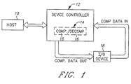
- a data processing system comprises a host computer 10 which transmits data to and receives data from a device controller 12 that includes compression/decompression apparatus 14.
- Apparatus 14 comprises a compression engine 15 and a decompression engine 16 which can be invoked, respectively, to compress and decompress data.
- Engine 15 provides compressed data output to an input/output (I/O) device 18, such as a disk drive comprising a plurality of disks.
- I/O input/output
- Device 18 provides compressed data input to the decompression engine 16 of device controller 12.
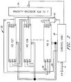
- data compression/ decompression apparatus 14 comprises a control unit 20, a history buffer 22, and a priority encoder 24.
- Input/output (I/O) bus 11 conveys data to and from control unit 20.
- the data is in the form of "symbols", a term used generically to connote bytes, halfwords, words, or any other preselected number of bits. However, to facilitate understanding, the data is herein assumed to be in the form of bytes.
- history buffer 22 consists of an array of 128 identical horizontal slice units HS0 to HS127, each of which stores four bytes, for thereby partitioning the buffer into four 128-byte stored blocks.
- This modular architecture creates a history buffer 22 capable of storing 512 (128 x 4) consecutive bytes in which the bytes in each HS unit are separated by exactly 128 bytes (i.e., one block size) and each HS unit stores four bytes, one from each block.
- Each byte b in buffer 22 has a unique address which is identified by its block index B and HS index.
- the block index B is 0; for bytes 128-255, the block index B is 1; for bytes 256-383, the block index B is 2; and for bytes 384-511, the block index B is 3.
- the HS index is the byte address mod block size.
- the address of byte 356 would be [2,100].
- Four bytes b, one from each block at the same HS address 0...127 comprise a word W whose address in this case would be (1,L;2,L;3,L;4,L) where L is a specific HS address.
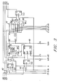
- each HS unit comprises a memory register or cell ME, an address selector cell SE, a comparator cell CO, a multiplexer MU and latches S1, S2, S3.
- Controller 20 transmits to each HS unit the same 8-bit byte of an incoming symbol string and four signals c1-c4 that control the multiplexer MU of that HS unit.
- Controller 20 also provides in parallel to each HS unit: signals r1 and r2 for use in resetting latches S1 and S2, respectively; block address selecting signals ad1 and ad2, respectively; a clock signal ck that synchronizes operation of all HS units; and a write enable signal w.
- Each HS unit has outputs s1o, s2o, s3o which represent the current states of the respective latches S1, S2, S3. These outputs constitute the inputs s1i, s2i, s3i (see Fig. 2) for the next successive HS unit in a cyclical manner, with the outputs s1o, s3o from HS127 being the inputs s1i, s3i to HS0.
- Multiplexer MU uses the control signals c1-c4, and generates an output m.
- buffer 22 i.e., 1L, 2L, 3L, 4L, S1, S2, S3
- This state occurs whenever a new sector is compressed.
- a signal r1 is sent in parallel by control unit 20 to AND gate 42 in all HS units to reset the latches S1 in all HS units.
- a byte can only be written into a location in the memory cell of a given HS unit under the following conditions:
- This procedure is repeated (i.e., resetting of the S1 latches in all HS units and maintaining the initializing "1" signal on line 44) until all blocks are full; whereupon the signal on line 44 is switched by control unit 20 to "0" .
- the latch S1 of each HS unit also provides the output slo of that unit. Consequently, the S1 latches of all HS units act as a 128-bit shift register. This shift register is updated by write enable signal w which is transmitted in parallel to all HS units from control unit 20.
- Write enable signal w also causes an incoming byte from line 48 to be written into the memory cell ME of the HS unit.
- the location is determined by the latches S1 and inputs s1i to be one of the locations 1L, 2L, 3L or 4L as determined by the selector unit SE.
- One of the advantages of the latches S1 is the fact that the memory cells need not be reset at the beginning of a new sector, thus reducing power consumption. This feature is of practical importance in a device controller implementation where power dissipation is critical due to battery power source limitations.
- control unit 20 sends a signal r2 in parallel to all HS units to reset latch S2 via AND gate 40.
- the output of s2 controls the selector cell SE in each HS unit.
- control unit 20 sends two signals ad1 and ad2 to the SE cells of all HS units.
- These two-bit signals ad1 and ad2 denote adjacent block addresses (e.g., B1 and B2).
- ad1 or ad2 becomes the determining block address ado for that HS unit. Initially because all S2 latches are reset, ado equals ad1 for all HS units.
- the output of the S2 latch of an HS unit becomes output s2o and then input s2i for the next HS unit.
- all latches S2 form a 128-bit shift register whose input (s2i from HS0) is always “1".
- this shift register is filled with "1"s from the bottom, thus causing more and more HS units to select ad2 instead of ad1.
- the incoming byte is also transmitted via branches of line 48 to a corresponding comparator cell CO in each HS unit.
- the comparator cells CO in all 128 HS units compare the incoming byte simultaneously with 128 bytes in that particular one of the four blocks chosen by the selector cells SE. If the output byte from one of the memory cells ME matches the incoming byte in line 48, comparator CO will provide a "1" output signal m to multiplexor unit MU.
- Multiplexor unit MU is conditioned by control unit 20 into one of four modes or states, as determined by the signals c1-c4.
- the functions implemented by these signals are as follows:
- a continued match requires that the preceding byte must also have been matched, a condition which is denoted by the input signal s3i from the preceding HS unit.
- the multiplexor MU is conditioned by signal c1 or c2
- the signal s3i can be ignored because s3i denotes the match of an initial byte of a string.
- the m signal of comparator cell CO is selectively ANDed with signal c1 at 52, with signals c2 and s1o at 54, with signals c3 and s1o and s3i at 56, and with signals c4 and s3i at 58.
- the outputs of the respective AND gates 52, 54, 56 and 58 are ORed at 60, generating the output signal m. If the output signal m is "1", it denotes that a matching string in buffer 22 has been extended to include the most recent incoming byte.
- the m outputs of all HS units are ORed at gate 62 (Fig. 2) to signal control unit 20 that the present input sequence has found an active match in the currently active block.
- This output signal m of an HS unit is also input to the latch S3. Therefore, if the output s3o of latch S3 of an HS unit is "1", it means that the buffer location determined by this unit and the address ado is the thus far last byte of a previously stored sequence that matches the most recent input sequence.
- the s3o outputs of each HS unit are connected to priority encoder 24.
- updating of buffer 22 is independent of and can be done concurrently with a string comparison operation.
- Priority encoder 24 uses the s3o outputs from the 128 HS units to calculate and encode the ending address of a sequence in history buffer 22 that matches the most recent sequence in the incoming data to be compressed. In a parallel implementation, such as herein described, more than one sequence in the history buffer 22 may match the incoming sequence. In such event, encoder 24 will provide only a single ending address for a matching sequence.
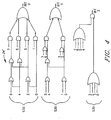
- the simplified priority encoder 24' receives as inputs the eight s3o signals from all (now 8) HS units. It then determines the lowest of the eight indices among the HS units for which s3o is "1". This is achieved by the logic illustrated in Fig. 4 which ignores all the s3o signals except the one with the smallest HS address. Thus, it determines a unique ending address of a matched sequence. This address is sent to control unit 20.
- the decompression algorithm requires the starting address of a matching sequence, it is necessary to calculate this starting address from the ending address provided by the priority encoder 24. Since it is known that the matching sequence started in the currently active block (all S2 latches were reset initially), it is only necessary to calculate the last seven bits of the address. This can be done by simply subtracting the length of the matching sequence; i.e., subtracting the number of bits in this sequence from the ending address and taking the result mod the number of HS units (128 in the embodiment illustrated in Fig. 3). The length of the matching sequence is part of the compressed data and therefore available in the control unit 20 where it is easily obtained with an incrementing counter.
- the algorithm for decompressing the data which has been compressed by applicants' modified LZ1 compression algorithm, is inherently sequential and therefore independent of the degree of parallelism used in compression engine 15.
- the history buffer 22 of compression engine 15 is used.
- the compressed incoming data consists of a starting buffer address, a string length number, and a character that is the last symbol in the compressed string.
- Control unit 20 extracts the buffer content at the initial address and updates buffer 22 with the extracted symbol in the same fashion as compression engine 15. This step is repeated for the length of the compressed string. During this process, the buffer address is constantly incremented in a cyclical fashion. Finally, the last symbol is also sent to host 10, and the control unit 20 is once again ready to receive the data of the next compressed string.
- APPENDIX A a program in C language for implementing the LZ1 compression algorithm in accordance with the invention
- APPENDIX B a program in C language for decompressing data compressed by use of applicants' modified LZ1 compression algorithm.
- the programs in both Appendices are provided with comments to provide additional illustrations of the sequences of steps in implementing the compression/decompression described above.
Landscapes
- Engineering & Computer Science (AREA)
- Theoretical Computer Science (AREA)
- Multimedia (AREA)
- Physics & Mathematics (AREA)
- General Physics & Mathematics (AREA)
- Compression, Expansion, Code Conversion, And Decoders (AREA)
- Reduction Or Emphasis Of Bandwidth Of Signals (AREA)
- Separation By Low-Temperature Treatments (AREA)
- Eye Examination Apparatus (AREA)
- Measuring Pulse, Heart Rate, Blood Pressure Or Blood Flow (AREA)
- Measuring And Recording Apparatus For Diagnosis (AREA)
- Apparatus For Radiation Diagnosis (AREA)
- Record Information Processing For Printing (AREA)
Claims (9)
- Datenkomprimierungsvorrichtung, die das Folgende umfasst:eine Gruppierung (22) von i identischen Scheibeneinheiten, von denen jede j Symbole speichert, um j getrennte Blöcke zu definieren, die ein Symbol aus jeder Scheibeneinheit umfassen, wobei die Symbole in jeder Scheibeneinheit durch genau i Symbole getrennt werden;i Vergleicher, von denen jeder mit einer Scheibeneinheit verbunden ist, um zum Kennzeichnen von übereinstimmenden Symbolfolgen jedes Symbol in einer Kette von i ankommenden Symbolen parallel mit den Symbolen zu vergleichen, die vorher in den Scheibeneinheiten gespeichert worden sind; undMittel zum Steuern der Vergleicher, um Symbole gegenüber den Scheibeneinheiten parallel, aber in jedem der Blöcke der Reihe nach, abzutasten.
- Vorrichtung nach Anspruch 1, wobei jede Scheibeneinheit ein Ausgabesignal bereitstellt, das anzeigt, ob eine übereinstimmende Folge gekennzeichnet worden ist, und wobei die Vorrichtung weiterhin einen Prioritätscodierer (24), um aus dem Ausgabesignal jede j,i Adresse zu berechnen, in der eine übereinstimmende Folge gekennzeichnet wurde, und Mittel enthält, um eine der j,i Adressen auszuwählen, für die eine übereinstimmende Folge gekennzeichnet wurde.
- Vorrichtung nach Anspruch 2, wobei das Ausgabesignal das letzte Byte einer vorher gespeicherten Folge so weit kennzeichnet, wie die letzte Folge in der Kette der ankommenden Symbole damit übereinstimmt.
- Vorrichtung nach einem beliebigen vorhergehenden Anspruch, die weiterhin Mittel zum Verhindern der Einwirkung des Algorithmus auf jegliche Blöcke enthält, die keine Symbole enthalten.
- Vorrichtung nach einem beliebigen vorhergehenden Anspruch, die das Folgende enthält:einen einzelnen Zwischenspeicher in jeder der Scheibeneinheiten, wobei die Zwischenspeicher in Serie geschaltet sind, um zusammen ein Schieberegister zu bilden; undMittel zum Rückstellen der Zwischenspeicher und damit des Schieberegisters, ehe Symbole in der Gruppierung gespeichert werden.
- Vorrichtung nach einem beliebigen vorhergehenden Anspruch, die weiterhin Mittel enthält, die bewirken, dass übereinstimmende Folgen und nicht übereinstimmende Folgen von Symbolen in der Gruppierung gespeichert werden.
- Vorrichtung nach Anspruch 6, die weiterhin Mittel zum Aufzeichnen der ankommenden Symbole der Reihe nach in aufeinanderfolgende Symbolpositionen in der Gruppierung enthält, bis alle Gruppierungspositionen gefüllt sind; undnachfolgendes Ersetzen der ältesten Symbolkette in der Gruppierung durch das ankommende Symbol.
- Verfahren zum Komprimieren von Daten, welches das Folgende umfasst:Unterteilen einer Gruppierung (22) in i identische Scheibeneinheiten, von denen jede j Symbole speichert, um j getrennte Blöcke zu definieren, die ein Symbol aus jeder Scheibeneinheit umfassen, wobei die Symbole in jeder Scheibeneinheit durch genau i Symbole getrennt werden;unter Verwendung von i Vergleichern, die jeweils mit einer Scheibeneinheit verbunden sind, Vergleichen jedes Symbols in einer Kette von i ankommenden Symbolen parallel mit den Symbolen, die vorher in den Scheibeneinheiten gespeichert worden sind, um übereinstimmende Symbolfolgen zu kennzeichnen; undSteuern der Vergleicher, um Symbole gegenüber den Scheibeneinheiten parallel, aber in jedem der Blöcke der Reihe nach, abzutasten.
- Verfahren nach Anspruch 8, das den folgenden Schritt enthält:Auswählen von Parametern i und j, um die Anzahl der Vergleicher zu begrenzen, die erforderlich sind, um einen gewünschten Grad von Leistungsfähigkeit bei der Ausführung des Algorithmus zu erreichen, der auf einem Kompromiss zwischen Ausführungsgeschwindigkeit des Algorithmus und Kosten der Hardware beruht.
Applications Claiming Priority (2)
| Application Number | Priority Date | Filing Date | Title |
|---|---|---|---|
| US08/089,211 US5384567A (en) | 1993-07-08 | 1993-07-08 | Combination parallel/serial execution of sequential algorithm for data compression/decompression |
| US89211 | 1993-07-08 |
Publications (3)
| Publication Number | Publication Date |
|---|---|
| EP0633668A2 EP0633668A2 (de) | 1995-01-11 |
| EP0633668A3 EP0633668A3 (de) | 1996-01-31 |
| EP0633668B1 true EP0633668B1 (de) | 2000-05-03 |
Family
ID=22216343
Family Applications (1)
| Application Number | Title | Priority Date | Filing Date |
|---|---|---|---|
| EP94304678A Expired - Lifetime EP0633668B1 (de) | 1993-07-08 | 1994-06-27 | Datenkomprimierungsvorrichtung |
Country Status (12)
| Country | Link |
|---|---|
| US (1) | US5384567A (de) |
| EP (1) | EP0633668B1 (de) |
| JP (1) | JP3083708B2 (de) |
| KR (1) | KR0166048B1 (de) |
| CN (1) | CN1102812C (de) |
| AT (1) | ATE192614T1 (de) |
| BR (1) | BR9402666A (de) |
| CA (1) | CA2122170A1 (de) |
| DE (1) | DE69424229T2 (de) |
| ES (1) | ES2145100T3 (de) |
| SG (1) | SG45138A1 (de) |
| TW (1) | TW303549B (de) |
Families Citing this family (24)
| Publication number | Priority date | Publication date | Assignee | Title |
|---|---|---|---|---|
| US5574834A (en) * | 1992-01-09 | 1996-11-12 | Matsushita Graphic Communications Systems, Inc. | Image communication system for following a communication procedure to simultaneously transmit image code data |
| JP3242795B2 (ja) * | 1994-10-17 | 2001-12-25 | 富士通株式会社 | データ処理装置及びデータ処理方法 |
| US5771010A (en) * | 1995-03-22 | 1998-06-23 | Ibm Corporation | Apparatus for compressing data using a Lempel-Ziv-type algorithm |
| US5913216A (en) * | 1996-03-19 | 1999-06-15 | Lucent Technologies, Inc. | Sequential pattern memory searching and storage management technique |
| US5771011A (en) * | 1996-07-15 | 1998-06-23 | International Business Machines Corporation | Match detect logic for multi-byte per cycle hardware data compression |
| US5798718A (en) * | 1997-05-12 | 1998-08-25 | Lexmark International, Inc. | Sliding window data compression method and apparatus |
| US6009372A (en) * | 1997-10-01 | 1999-12-28 | Cummins Engine Company, Inc. | Management of programming and memory space for an internal combustion engine control system |
| EP0977152A3 (de) * | 1998-07-28 | 2000-12-27 | Xerox Corporation | Verfahren zur Datenkomprimierung unter Verwendung von Zeichenkettenanpassung |
| KR100539862B1 (ko) | 2001-04-04 | 2005-12-28 | 삼성전자주식회사 | 부호분할다중접속 이동통신시스템에서 데이타 송/수신장치및 방법 |
| US6657565B2 (en) * | 2002-03-21 | 2003-12-02 | International Business Machines Corporation | Method and system for improving lossless compression efficiency |
| US7206962B2 (en) * | 2003-11-25 | 2007-04-17 | International Business Machines Corporation | High reliability memory subsystem using data error correcting code symbol sliced command repowering |
| US7180433B1 (en) * | 2005-09-22 | 2007-02-20 | Tandberg Storage Asa | Fast data compression and decompression system and method |
| IL205528A (en) * | 2009-05-04 | 2014-02-27 | Storwize Ltd | A method and system for compressing logical information objects for storage |
| US8248279B2 (en) | 2010-10-26 | 2012-08-21 | Hewlett-Packard Development Company, L.P. | History buffer apparatus and method for adaptive lossless data compression |
| KR20160070512A (ko) | 2014-12-10 | 2016-06-20 | 삼성전자주식회사 | 반도체 장치 및 그 동작 방법 |
| US10073699B2 (en) | 2015-10-14 | 2018-09-11 | International Business Machines Corporation | Processing instructions in parallel with waw hazards and via a distributed history buffer in a microprocessor having a multi-execution slice architecture |
| US10289415B2 (en) | 2015-10-14 | 2019-05-14 | International Business Machines Corporation | Method and apparatus for execution of threads on processing slices using a history buffer for recording architected register data |
| US10255071B2 (en) | 2015-10-14 | 2019-04-09 | International Business Machines Corporation | Method and apparatus for managing a speculative transaction in a processing unit |
| US10282205B2 (en) | 2015-10-14 | 2019-05-07 | International Business Machines Corporation | Method and apparatus for execution of threads on processing slices using a history buffer for restoring architected register data via issued instructions |
| CN107508602A (zh) * | 2017-09-01 | 2017-12-22 | 郑州云海信息技术有限公司 | 一种数据压缩方法、系统及其cpu处理器 |
| CN110311687B (zh) * | 2019-07-09 | 2022-10-04 | 上海天数智芯半导体有限公司 | 一种基于集成算法的时序数据无损压缩方法 |
| KR102901330B1 (ko) * | 2019-12-16 | 2025-12-17 | 한화오션 주식회사 | 볼트 페인트 제거 장비 |
| RU2729509C1 (ru) * | 2019-12-23 | 2020-08-07 | федеральное государственное автономное образовательное учреждение высшего образования "Национальный исследовательский ядерный университет МИФИ" (НИЯУ МИФИ) | Устройство для распаковки данных |
| CN112783056B (zh) * | 2021-01-04 | 2022-09-23 | 潍柴动力股份有限公司 | Ecu的数据烧写方法、装置、设备及存储介质 |
Family Cites Families (9)
| Publication number | Priority date | Publication date | Assignee | Title |
|---|---|---|---|---|
| US3432686A (en) * | 1966-05-02 | 1969-03-11 | Sperry Rand Corp | Search memory match logic detector |
| GB1378143A (en) * | 1971-07-23 | 1974-12-18 | Int Computers Ltd | Data processors |
| FR2600223B1 (fr) * | 1986-01-13 | 1988-08-19 | Thomson Cgr | Procede de formattage et de deformattage de donnees resultant du codage d'informations numeriques a l'aide d'un code a longueur variable, et dispositif de mise en oeuvre |
| GB2189970B (en) * | 1986-05-01 | 1990-03-28 | British Broadcasting Corp | Data conversion |
| US5003307A (en) | 1989-01-13 | 1991-03-26 | Stac, Inc. | Data compression apparatus with shift register search means |
| US5016009A (en) | 1989-01-13 | 1991-05-14 | Stac, Inc. | Data compression apparatus and method |
| EP0459703B1 (de) * | 1990-05-31 | 2000-08-16 | STMicroelectronics, Inc. | Inhaltsadressierbarer Speicher |
| US5179378A (en) * | 1991-07-30 | 1993-01-12 | University Of South Florida | Method and apparatus for the compression and decompression of data using Lempel-Ziv based techniques |
| CA2077271C (en) * | 1991-12-13 | 1998-07-28 | David J. Craft | Method and apparatus for compressing data |
-
1993
- 1993-07-08 US US08/089,211 patent/US5384567A/en not_active Expired - Fee Related
-
1994
- 1994-04-26 CA CA002122170A patent/CA2122170A1/en not_active Abandoned
- 1994-06-07 CN CN94106536A patent/CN1102812C/zh not_active Expired - Fee Related
- 1994-06-08 KR KR1019940013086A patent/KR0166048B1/ko not_active Expired - Fee Related
- 1994-06-27 SG SG1996000352A patent/SG45138A1/en unknown
- 1994-06-27 EP EP94304678A patent/EP0633668B1/de not_active Expired - Lifetime
- 1994-06-27 ES ES94304678T patent/ES2145100T3/es not_active Expired - Lifetime
- 1994-06-27 AT AT94304678T patent/ATE192614T1/de not_active IP Right Cessation
- 1994-06-27 DE DE69424229T patent/DE69424229T2/de not_active Expired - Fee Related
- 1994-07-04 JP JP06152342A patent/JP3083708B2/ja not_active Expired - Fee Related
- 1994-07-08 BR BR9402666A patent/BR9402666A/pt not_active IP Right Cessation
- 1994-07-18 TW TW083106551A patent/TW303549B/zh active
Also Published As
| Publication number | Publication date |
|---|---|
| SG45138A1 (en) | 1998-01-16 |
| CN1106595A (zh) | 1995-08-09 |
| EP0633668A2 (de) | 1995-01-11 |
| DE69424229D1 (de) | 2000-06-08 |
| US5384567A (en) | 1995-01-24 |
| EP0633668A3 (de) | 1996-01-31 |
| DE69424229T2 (de) | 2000-11-30 |
| TW303549B (de) | 1997-04-21 |
| ATE192614T1 (de) | 2000-05-15 |
| CA2122170A1 (en) | 1995-01-09 |
| KR0166048B1 (ko) | 1999-03-20 |
| CN1102812C (zh) | 2003-03-05 |
| JP3083708B2 (ja) | 2000-09-04 |
| BR9402666A (pt) | 1995-05-02 |
| JPH0795093A (ja) | 1995-04-07 |
| KR950004759A (ko) | 1995-02-18 |
| ES2145100T3 (es) | 2000-07-01 |
Similar Documents
| Publication | Publication Date | Title |
|---|---|---|
| EP0633668B1 (de) | Datenkomprimierungsvorrichtung | |
| US5175543A (en) | Dictionary reset performance enhancement for data compression applications | |
| US5563595A (en) | Method and apparatus for compressing data | |
| EP0573208B1 (de) | Verfahren und Vorrichtung zur Verwaltung von mehreren Wörterbüchern zur Datenkomprimierung mit Inhaltsadressierung | |
| US5455576A (en) | Apparatus and methods for Lempel Ziv data compression with improved management of multiple dictionaries in content addressable memory | |
| CA2077271C (en) | Method and apparatus for compressing data | |
| US6819271B2 (en) | Parallel compression and decompression system and method having multiple parallel compression and decompression engines | |
| US5771011A (en) | Match detect logic for multi-byte per cycle hardware data compression | |
| US5243341A (en) | Lempel-Ziv compression scheme with enhanced adapation | |
| US5936560A (en) | Data compression method and apparatus performing high-speed comparison between data stored in a dictionary window and data to be compressed | |
| US20020101367A1 (en) | System and method for generating optimally compressed data from a plurality of data compression/decompression engines implementing different data compression algorithms | |
| EP4030628B1 (de) | Speichernahe beschleunigung der wörterbuchdecodierung | |
| US6442680B1 (en) | Method and system for compressing reduced instruction set computer (RISC) executable code | |
| RU2450441C1 (ru) | Способ и устройство сжатия данных | |
| US5745603A (en) | Two dimensional context model obtained without a line buffer for arithmetic coding | |
| JP3171510B2 (ja) | 辞書ベースのメモリ内のデータを圧縮および圧縮解除する方法 | |
| EP0957586A1 (de) | Verfahren zur Datenkompression | |
| HK1012135B (en) | Dictionary reset performance enhancement for data compression applications | |
| HK1011122B (en) | Apparatus and method for managing multiple dictionaries in content addressable based data compression | |
| WO2017037502A1 (en) | Compression code and method by location |
Legal Events
| Date | Code | Title | Description |
|---|---|---|---|
| PUAI | Public reference made under article 153(3) epc to a published international application that has entered the european phase |
Free format text: ORIGINAL CODE: 0009012 |
|
| AK | Designated contracting states |
Kind code of ref document: A2 Designated state(s): AT BE CH DE ES FR GB IT LI NL SE |
|
| 17P | Request for examination filed |
Effective date: 19950519 |
|
| PUAL | Search report despatched |
Free format text: ORIGINAL CODE: 0009013 |
|
| AK | Designated contracting states |
Kind code of ref document: A3 Designated state(s): AT BE CH DE ES FR GB IT LI NL SE |
|
| GRAG | Despatch of communication of intention to grant |
Free format text: ORIGINAL CODE: EPIDOS AGRA |
|
| 17Q | First examination report despatched |
Effective date: 19990701 |
|
| GRAG | Despatch of communication of intention to grant |
Free format text: ORIGINAL CODE: EPIDOS AGRA |
|
| GRAH | Despatch of communication of intention to grant a patent |
Free format text: ORIGINAL CODE: EPIDOS IGRA |
|
| GRAH | Despatch of communication of intention to grant a patent |
Free format text: ORIGINAL CODE: EPIDOS IGRA |
|
| GRAA | (expected) grant |
Free format text: ORIGINAL CODE: 0009210 |
|
| AK | Designated contracting states |
Kind code of ref document: B1 Designated state(s): AT BE CH DE ES FR GB IT LI NL SE |
|
| PG25 | Lapsed in a contracting state [announced via postgrant information from national office to epo] |
Ref country code: NL Free format text: LAPSE BECAUSE OF FAILURE TO SUBMIT A TRANSLATION OF THE DESCRIPTION OR TO PAY THE FEE WITHIN THE PRESCRIBED TIME-LIMIT Effective date: 20000503 Ref country code: LI Free format text: LAPSE BECAUSE OF FAILURE TO SUBMIT A TRANSLATION OF THE DESCRIPTION OR TO PAY THE FEE WITHIN THE PRESCRIBED TIME-LIMIT Effective date: 20000503 Ref country code: FR Free format text: LAPSE BECAUSE OF FAILURE TO SUBMIT A TRANSLATION OF THE DESCRIPTION OR TO PAY THE FEE WITHIN THE PRESCRIBED TIME-LIMIT Effective date: 20000503 Ref country code: CH Free format text: LAPSE BECAUSE OF FAILURE TO SUBMIT A TRANSLATION OF THE DESCRIPTION OR TO PAY THE FEE WITHIN THE PRESCRIBED TIME-LIMIT Effective date: 20000503 Ref country code: BE Free format text: LAPSE BECAUSE OF FAILURE TO SUBMIT A TRANSLATION OF THE DESCRIPTION OR TO PAY THE FEE WITHIN THE PRESCRIBED TIME-LIMIT Effective date: 20000503 Ref country code: AT Free format text: LAPSE BECAUSE OF FAILURE TO SUBMIT A TRANSLATION OF THE DESCRIPTION OR TO PAY THE FEE WITHIN THE PRESCRIBED TIME-LIMIT Effective date: 20000503 |
|
| REF | Corresponds to: |
Ref document number: 192614 Country of ref document: AT Date of ref document: 20000515 Kind code of ref document: T |
|
| REG | Reference to a national code |
Ref country code: CH Ref legal event code: EP |
|
| REF | Corresponds to: |
Ref document number: 69424229 Country of ref document: DE Date of ref document: 20000608 |
|
| PGFP | Annual fee paid to national office [announced via postgrant information from national office to epo] |
Ref country code: FR Payment date: 20000616 Year of fee payment: 7 |
|
| ITF | It: translation for a ep patent filed | ||
| REG | Reference to a national code |
Ref country code: ES Ref legal event code: FG2A Ref document number: 2145100 Country of ref document: ES Kind code of ref document: T3 |
|
| PG25 | Lapsed in a contracting state [announced via postgrant information from national office to epo] |
Ref country code: SE Free format text: LAPSE BECAUSE OF FAILURE TO SUBMIT A TRANSLATION OF THE DESCRIPTION OR TO PAY THE FEE WITHIN THE PRESCRIBED TIME-LIMIT Effective date: 20000803 |
|
| EN | Fr: translation not filed | ||
| NLV1 | Nl: lapsed or annulled due to failure to fulfill the requirements of art. 29p and 29m of the patents act | ||
| REG | Reference to a national code |
Ref country code: CH Ref legal event code: PL |
|
| PLBE | No opposition filed within time limit |
Free format text: ORIGINAL CODE: 0009261 |
|
| STAA | Information on the status of an ep patent application or granted ep patent |
Free format text: STATUS: NO OPPOSITION FILED WITHIN TIME LIMIT |
|
| 26N | No opposition filed | ||
| REG | Reference to a national code |
Ref country code: GB Ref legal event code: IF02 |
|
| PGFP | Annual fee paid to national office [announced via postgrant information from national office to epo] |
Ref country code: IT Payment date: 20060630 Year of fee payment: 13 |
|
| PGFP | Annual fee paid to national office [announced via postgrant information from national office to epo] |
Ref country code: ES Payment date: 20070606 Year of fee payment: 14 |
|
| PGFP | Annual fee paid to national office [announced via postgrant information from national office to epo] |
Ref country code: DE Payment date: 20070619 Year of fee payment: 14 |
|
| PGFP | Annual fee paid to national office [announced via postgrant information from national office to epo] |
Ref country code: GB Payment date: 20070619 Year of fee payment: 14 |
|
| GBPC | Gb: european patent ceased through non-payment of renewal fee |
Effective date: 20080627 |
|
| PG25 | Lapsed in a contracting state [announced via postgrant information from national office to epo] |
Ref country code: DE Free format text: LAPSE BECAUSE OF NON-PAYMENT OF DUE FEES Effective date: 20090101 |
|
| PG25 | Lapsed in a contracting state [announced via postgrant information from national office to epo] |
Ref country code: GB Free format text: LAPSE BECAUSE OF NON-PAYMENT OF DUE FEES Effective date: 20080627 |
|
| REG | Reference to a national code |
Ref country code: ES Ref legal event code: FD2A Effective date: 20080628 |
|
| PG25 | Lapsed in a contracting state [announced via postgrant information from national office to epo] |
Ref country code: IT Free format text: LAPSE BECAUSE OF NON-PAYMENT OF DUE FEES Effective date: 20070627 |
|
| PG25 | Lapsed in a contracting state [announced via postgrant information from national office to epo] |
Ref country code: ES Free format text: LAPSE BECAUSE OF NON-PAYMENT OF DUE FEES Effective date: 20080628 |