EP0633170A1 - Wiper blade for windscreens of vehicles - Google Patents
Wiper blade for windscreens of vehicles Download PDFInfo
- Publication number
- EP0633170A1 EP0633170A1 EP94110648A EP94110648A EP0633170A1 EP 0633170 A1 EP0633170 A1 EP 0633170A1 EP 94110648 A EP94110648 A EP 94110648A EP 94110648 A EP94110648 A EP 94110648A EP 0633170 A1 EP0633170 A1 EP 0633170A1
- Authority
- EP
- European Patent Office
- Prior art keywords
- wiper blade
- main bracket
- spoiler
- openings
- main bow
- Prior art date
- Legal status (The legal status is an assumption and is not a legal conclusion. Google has not performed a legal analysis and makes no representation as to the accuracy of the status listed.)
- Granted
Links
- 210000000078 claw Anatomy 0.000 claims abstract description 5
- 230000001154 acute effect Effects 0.000 claims description 2
- 238000004140 cleaning Methods 0.000 abstract 1
- 230000006866 deterioration Effects 0.000 description 1
- 238000011161 development Methods 0.000 description 1
- 230000018109 developmental process Effects 0.000 description 1
Images
Classifications
-
- B—PERFORMING OPERATIONS; TRANSPORTING
- B60—VEHICLES IN GENERAL
- B60S—SERVICING, CLEANING, REPAIRING, SUPPORTING, LIFTING, OR MANOEUVRING OF VEHICLES, NOT OTHERWISE PROVIDED FOR
- B60S1/00—Cleaning of vehicles
- B60S1/02—Cleaning windscreens, windows or optical devices
- B60S1/04—Wipers or the like, e.g. scrapers
- B60S1/32—Wipers or the like, e.g. scrapers characterised by constructional features of wiper blade arms or blades
- B60S1/38—Wiper blades
- B60S1/3806—Means, or measures taken, for influencing the aerodynamic quality of the wiper blades
Definitions
- the invention is based on a wiper blade according to the preamble of the main claim.
- a wiper blade is already known (DE-PS 35 32 536), in which the openings arranged in the base wall of the main bracket are at most as wide as the distance between the two U-legs allows.
- the full width of the U-leg which has a certain height for reasons of strength and is opposite the spoiler, lies in the air flow, which leads to undesirable turbulence in the air flow and thus to a deterioration in the wiping quality at higher driving speeds.
- the wiper blade according to the invention with the characterizing features of the main claim has the advantage that the rear U-leg lying in the air flow can be made considerably narrower in the area of the openings, so that the turbulence is significantly reduced. At the same time, the openings move more in the direction of the incoming air flow, so that this can leave the main bar more easily and quickly through the opening, so that the negative pressure increases under the main bar. Furthermore, the area of the spoiler can be reduced by this measure. The required strength of the main bracket is ensured by the other U-leg and the spoiler arranged on it.
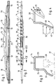
- FIG. 1 shows a windshield wiper blade in view
- FIG. 2 shows the windshield wiper blade according to FIG. 1 in plan view
- FIG. 3 shows a sectional area of a main wiper blade bracket in an enlarged view, with indicated wiper strip position, which results from a cut along the line III-III in FIG. 2 , when the wiper blade rests on a more curved disc
- FIG. 4 shows an enlarged sectional view of the main wiper blade bracket along the line IV-IV in FIG.
- a wiper blade 1 shown in view in FIG. 1 has a multi-membered support frame 12 which has a main bracket 14 and at its ends a beam or lower bracket or claw bracket 16.
- the main bracket 14 is elongated and has a U-shaped cross section, which is clear from Figures 3 and 4. It thus has a base wall 22 which connects two U-legs 24 and 26 which are arranged at a distance from one another. As FIG.
- FIG. 3 also shows the position of the wiper strip 20 in dash-dotted lines, in which it is located when the wiper blade 10 wipes over a more curved region of the windshield.
- the main bracket 14 has in its central region a so-called hanging box 34, in which a hanging axis 36 for connecting the wiper blade to a driven wiper arm, not shown, is arranged.
- the air flowing on its side provided with the spoiler 30 is particularly strong from the head wind, which is indicated in FIG. 2 by the arrows 38.
- part of the headwind (arrow 40) passes behind the spoiler 30 through a gap 42 (FIG. 3) that results between the free end of the spoiler and the surface of the window 32 to be wiped.
- This partial stream 40 flows, in particular, the main bracket 14 from below and tries to lift the wiper blade 14 off the window. It is therefore important to offer this partial flow 40 as little contact surface as possible and to remove it quickly from the wiper blade area. This is achieved particularly advantageously in that the openings 28 extend into the U-leg 26 of the main bracket 14 facing away from the spoiler 30.
- the Openings 28 have a side edge 42, which enclose an acute angle ⁇ with a longitudinal axis 44 of the main bracket 14.
- the direction of inclination of the side edge 42 is such that it runs approximately horizontally when the wiper blade 10 has covered half of its pendulum angle, which is essentially between 90 ° and 100 °, on the disk 32, because in this position the wiper blade has its most direct flow through experiences the wind flow deflected to the side on the pane. This is guided through the openings 28 arranged in this way almost without interference through the main bracket 14.
Landscapes
- Engineering & Computer Science (AREA)
- Physics & Mathematics (AREA)
- Fluid Mechanics (AREA)
- Quality & Reliability (AREA)
- Mechanical Engineering (AREA)
- Rear-View Mirror Devices That Are Mounted On The Exterior Of The Vehicle (AREA)
- Body Structure For Vehicles (AREA)
- Brushes (AREA)
- Vehicle Cleaning, Maintenance, Repair, Refitting, And Outriggers (AREA)
Abstract
Description
Die Erfindung geht aus von einem Wischblatt nach der Gattung des Hauptanspruchs. Es ist schon ein solches Wischblatt bekannt (DE-PS 35 32 536), bei dem die in der Basiswand des Hauptbügels angeordneten Durchbrechungen höchstens so breit sind, wie dies der Abstand zwischen den beiden U-Schenkel zuläßt. Dadurch liegt die volle Breite des aus Festigkeitsgründen eine bestimmte Höhe aufweisenden, dem Spoiler gegenüberliegenden U-Schenkel im Luftstrom, was zu unerwünschten Verwirbelungen des Luftstroms und damit zu einer Verschlechterung der Wischqualität bei höheren Fahrgeschwindigkeiten führt.The invention is based on a wiper blade according to the preamble of the main claim. Such a wiper blade is already known (DE-PS 35 32 536), in which the openings arranged in the base wall of the main bracket are at most as wide as the distance between the two U-legs allows. As a result, the full width of the U-leg, which has a certain height for reasons of strength and is opposite the spoiler, lies in the air flow, which leads to undesirable turbulence in the air flow and thus to a deterioration in the wiping quality at higher driving speeds.
Das erfindungsgemäße Wischblatt mit den kennzeichnenden Merkmalen des Hauptanspruchs hat demgegenüber den Vorteil, daß der im Luftstrom liegende hintere U-Schenkel im Bereich der Durchbrechungen erheblich schmaler ausgeführt werden kann, so daß die Verwirbelungen deutlich reduziert werden. Gleichzeitig rücken die Durchbrechungen mehr in die Richtung der ankommenden Luftströmung, so daß diese leichter und schneller durch die Durchbrechung hindurch den Hauptbügel verlassen kann, so daß unter dem Hauptbügel der Unterdruck größer wird. Weiter kann durch diese Maßnahme die Fläche des Spoilers reduziert werden. Die erforderliche Festigkeit des Hauptbügels wird durch den anderen U-Schenkel und den an diesen angeordneten Spoiler gewährleistet.The wiper blade according to the invention with the characterizing features of the main claim has the advantage that the rear U-leg lying in the air flow can be made considerably narrower in the area of the openings, so that the turbulence is significantly reduced. At the same time, the openings move more in the direction of the incoming air flow, so that this can leave the main bar more easily and quickly through the opening, so that the negative pressure increases under the main bar. Furthermore, the area of the spoiler can be reduced by this measure. The required strength of the main bracket is ensured by the other U-leg and the spoiler arranged on it.
Durch die in den Unteransprüchen aufgeführten Maßnahmen sind vorteilhafte Weiterbildungen und Verbesserungen des im Hauptanspruch angegebenen Wischblatts möglich.Advantageous further developments and improvements of the wiper blade specified in the main claim are possible through the measures listed in the subclaims.
Ein Ausführungsbeispiel der Erfindung ist in der Zeichnung dargestellt und in der nachfolgenden Beschreibung näher erläutert. Es zeigen Figur 1 ein Scheibenwischblatt in Ansicht, Figur 2 das Scheibenwischblatt gemäß Figur 1 in Draufsicht, Figur 3 eine Schnittfläche eines Wischblatt-Hauptbügels in vergrößerter Darstellung, mit angedeuteter Wischleistenposition, die sich bei einem Schnitt entlang der Linie III-III in Figur 2 ergibt, wenn das Wischblatt auf einer stärker gekrümmten Scheibe aufliegt und Figur 4 eine Schnittfläche des Wischblatthauptbügels entlang der Linie IV-IV in Figur 2 vergrößert dargestellt.An embodiment of the invention is shown in the drawing and explained in more detail in the following description. 1 shows a windshield wiper blade in view, FIG. 2 shows the windshield wiper blade according to FIG. 1 in plan view, FIG. 3 shows a sectional area of a main wiper blade bracket in an enlarged view, with indicated wiper strip position, which results from a cut along the line III-III in FIG. 2 , when the wiper blade rests on a more curved disc and FIG. 4 shows an enlarged sectional view of the main wiper blade bracket along the line IV-IV in FIG.
Ein in Figur 1 in Ansicht dargestelltes Wischblatt 1 weist ein mehrgliedriges Traggestell 12 auf, das einen Hauptbügel 14 und an dessen Enden waagebalkenartig angelenkte Unter- oder Krallenbügel 16 hat. Die Krallenbügel 16 fassen mit an ihren Enden angeordneten Krallenpaaren 18 eine langgestreckte Wischleiste 20. Sie übergreifen dabei den Rücken der Wischleiste 20 und fassen in Längsnuten, welche einander gegenüberliegend im Rückenbereich der Wischleiste angeordnet sind. Der Hauptbügel 14 ist langgestreckt und weist einen U-förmigen Querschnitt auf, was aus den Figuren 3 und 4 deutlich wird. Er hat somit eine Basiswand 22, die zwei mit Abstand voneinander angeordnete U-Schenkel 24 und 26 miteinander verbindet. Wie die Figur 2 weiter zeigt, hat der Hauptbügel 14 Durchbrechungen 28, die sich überwiegend in der Basiswand 22 befinden, sich jedoch noch bis in den Bereich des U-Schenkels 24 erstrecken. Dies ist besonders gut aus der Figur 4 ersichtlich. Der diesem U-Schenkel 26 gegenüberliegende andere U-Schenkel 24 ist mit einem Spoiler 30 versehen, der sich bis nahe an die zu wischende Scheibe 32 (Figur 3) erstreckt. In Figur 3 ist darüber hinaus mit strichpunktierten Linien die Position der Wischleiste 20 dargestellt, in der sich diese befindet, wenn das Wischblatt 10 über einen stärker gekrümmten Bereich der Windschutzscheibe wischt. Weiter weist der Hauptbügel 14 in seinem Mittelbereich einen sogenannten Einhängekasten 34 auf, in dem eine Einhängeachse 36 zum Verbinden des Wischblatts mit einem nicht dargestellten, angetriebenen Wischerarm angeordnet ist.A
Während des Betriebs des Wischblatts wird dieses auf seiner mit dem Spoiler 30 versehenen Seite besonders stark vom Fahrtwind angeströmt, der in Figur 2 durch die Pfeile 38 angedeutet ist. Ein Teil des Fahrtwindes (Pfeil 40) gelangt jedoch durch einen Spalt 42 (Figur 3), der sich zwischen dem freien Spoilerende und der Oberfläche der zu wischenden Scheibe 32 ergibt, hinter den Spoiler 30. Dieser Teilstrom 40 strömt insbesondere den Hauptbügel 14 von unten an und versucht das Wischblatt 14 von der Scheibe abzuheben. Es gilt also diesem Teilstrom 40 möglichst wenig Angriffsfläche zu bieten und rasch aus dem Wischblattbereich abzuführen. Dies wird besonders vorteilhaft dadurch erreicht, daß die Durchbrechungen 28 sich bis in den vom Spoiler 30 abgewandten U-Schenkel 26 des Hauptbügels 14 erstrecken. Wie aus Figur 2 ersichtlich ist, weisen die Durchbrechungen 28 eine Seitenkante 42 auf, die mit einer Längsachse 44 des Hauptbügels 14 einen spitzen Winkel α einschließen. Dabei ist die Neigungsrichtung der Seitenkante 42 so getroffen, daß sie etwa waagrecht verläuft, wenn das Wischblatt 10 die Hälfte seines im wesentlichen zwischen 90° und 100° betragenden Pendelwinkels auf der Scheibe 32 zurückgelegt hat, weil in dieser Stellung das Wischblatt seine direkteste Anströmung durch den auf der Scheibe zur Seite abgelenkten Fahrtwindstrom erfährt. Dieser wird durch die so angeordneten Durchbrechungen 28 fast störungsfrei durch den Hauptbügel 14 hindurchgeführt.During operation of the wiper blade, the air flowing on its side provided with the
Claims (3)
Applications Claiming Priority (2)
| Application Number | Priority Date | Filing Date | Title |
|---|---|---|---|
| DE9310261U | 1993-07-09 | ||
| DE9310261U DE9310261U1 (en) | 1993-07-09 | 1993-07-09 | Wiper blade for windows of motor vehicles |
Publications (2)
| Publication Number | Publication Date |
|---|---|
| EP0633170A1 true EP0633170A1 (en) | 1995-01-11 |
| EP0633170B1 EP0633170B1 (en) | 1998-04-08 |
Family
ID=6895404
Family Applications (1)
| Application Number | Title | Priority Date | Filing Date |
|---|---|---|---|
| EP94110648A Expired - Lifetime EP0633170B1 (en) | 1993-07-09 | 1994-07-08 | Wiper blade for windscreens of vehicles |
Country Status (4)
| Country | Link |
|---|---|
| US (1) | US5509166A (en) |
| EP (1) | EP0633170B1 (en) |
| DE (2) | DE9310261U1 (en) |
| ES (1) | ES2115107T3 (en) |
Cited By (10)
| Publication number | Priority date | Publication date | Assignee | Title |
|---|---|---|---|---|
| US9889822B2 (en) | 2014-03-07 | 2018-02-13 | Pylon Manufacturing Corp. | Windshield wiper connector and assembly |
| US10005431B2 (en) | 2011-04-21 | 2018-06-26 | Pylon Manufacturing Corp. | Vortex damping wiper blade |
| US10077026B2 (en) | 2012-02-24 | 2018-09-18 | Pylon Manufacturing Corp. | Wiper blade |
| US10166951B2 (en) | 2013-03-15 | 2019-01-01 | Pylon Manufacturing Corp. | Windshield wiper connector |
| US10189445B2 (en) | 2012-02-24 | 2019-01-29 | Pylon Manufacturing Corp. | Wiper blade |
| US10457252B2 (en) | 2011-07-28 | 2019-10-29 | Pylon Manufacturing Corp. | Windshield wiper adapter, connector and assembly |
| US10464533B2 (en) | 2011-04-21 | 2019-11-05 | Pylon Manufacturing Corp. | Wiper blade with cover |
| US10597004B2 (en) | 2011-07-29 | 2020-03-24 | Pylon Manufacturing Corporation | Windshield wiper connector |
| US10829092B2 (en) | 2012-09-24 | 2020-11-10 | Pylon Manufacturing Corp. | Wiper blade with modular mounting base |
| US11554754B2 (en) | 2016-05-19 | 2023-01-17 | Pylon Manufacturing Corporation | Windshield wiper blade |
Families Citing this family (50)
| Publication number | Priority date | Publication date | Assignee | Title |
|---|---|---|---|---|
| GB9509802D0 (en) * | 1995-05-15 | 1995-07-05 | Charng Cedric S K | Wiper blade assemblies |
| DE19536742A1 (en) * | 1995-10-02 | 1997-04-03 | Teves Gmbh Alfred | Wiper blade for a windshield wiper device of a vehicle |
| KR100249342B1 (en) * | 1998-02-21 | 2000-04-01 | 손일호 | Anti-lifting wiper |
| US7967855B2 (en) * | 1998-07-27 | 2011-06-28 | Icon Interventional Systems, Inc. | Coated medical device |
| US6675433B1 (en) | 2000-07-06 | 2004-01-13 | Trico Products Corporation | Beam blade wiper assembly having improved wind lift characteristics |
| US7150065B2 (en) * | 2000-07-27 | 2006-12-19 | Robert Bosch Gmbh | Wiper arm, wiper blade and wiper device, especially for the panes of a motor vehicle |
| US6665904B1 (en) * | 2000-09-25 | 2003-12-23 | Robert B. Kerchaert | Windshield wiper clip |
| US8740973B2 (en) * | 2001-10-26 | 2014-06-03 | Icon Medical Corp. | Polymer biodegradable medical device |
| CA2514372A1 (en) * | 2004-07-30 | 2006-01-30 | M Management-Tex, Ltd. | Windshield wiper structure |
| US20060265830A1 (en) * | 2005-02-14 | 2006-11-30 | Tenneco Automotive Operating Company Inc. | Encapsulated beam with anti-rotation system |
| US20060201601A1 (en) * | 2005-03-03 | 2006-09-14 | Icon Interventional Systems, Inc. | Flexible markers |
| US8323333B2 (en) * | 2005-03-03 | 2012-12-04 | Icon Medical Corp. | Fragile structure protective coating |
| US20060264914A1 (en) * | 2005-03-03 | 2006-11-23 | Icon Medical Corp. | Metal alloys for medical devices |
| WO2006110197A2 (en) * | 2005-03-03 | 2006-10-19 | Icon Medical Corp. | Polymer biodegradable medical device |
| EP1858440B1 (en) * | 2005-03-03 | 2024-04-24 | MiRus LLC | Improved metal alloys for medical device |
| US7774892B2 (en) | 2005-04-04 | 2010-08-17 | Trico Products Corporation | Wiper coupler and wiper assembly incorporating same |
| CA2541641C (en) | 2005-04-04 | 2014-02-11 | Trico Products Corporation | Wiper coupler and wiper assembly incorporating same |
| US7350259B2 (en) * | 2005-07-28 | 2008-04-01 | Tenneco Automotive Operating Company Inc. | Relative axial translation prevention system for wiper blade assemblies |
| US20070022556A1 (en) * | 2005-07-28 | 2007-02-01 | Walworth Van T | Wind deflector with symmetrical geometry |
| US7861363B2 (en) * | 2006-02-02 | 2011-01-04 | Trico Products Corporation | Beam blade windshield wiper assembly having an airfoil |
| US7802341B2 (en) * | 2006-10-24 | 2010-09-28 | Trico Products Corporation | Wiper system having a pin-style wiper arm and wiper assembly |
| USD613664S1 (en) * | 2009-05-12 | 2010-04-13 | Adm 21 Co., Ltd. | Wiper rubber |
| USD613666S1 (en) * | 2009-05-12 | 2010-04-13 | Adm 21 Co., Ltd. | Wiper rubber |
| USD613665S1 (en) * | 2009-05-12 | 2010-04-13 | Adm 21 Co., Ltd. | Wiper rubber |
| US8533899B2 (en) | 2009-08-27 | 2013-09-17 | Trico Products Corporation | Windshield wiper assembly |
| US8261403B2 (en) | 2010-05-13 | 2012-09-11 | Trico Products Corporation | Beam blade windshield wiper assembly |
| US8397341B2 (en) | 2010-05-13 | 2013-03-19 | Trico Products Corporation | Beam blade windshield wiper assembly |
| USD706200S1 (en) | 2010-09-22 | 2014-06-03 | Pylon Manufacturing Corporation | Windshield wiper cover |
| USD685712S1 (en) | 2011-03-23 | 2013-07-09 | Kcw Corporation | Wiper |
| US8806700B2 (en) | 2011-07-29 | 2014-08-19 | Pylon Manufacturing Corporation | Wiper blade connector |
| MX347284B (en) | 2011-07-29 | 2017-04-21 | Pylon Mfg Corp | Windshield wiper connector. |
| USD702618S1 (en) | 2012-11-15 | 2014-04-15 | Trico Products Corporation | Wiper blade coupler |
| USD704126S1 (en) | 2012-11-15 | 2014-05-06 | Trico Products Corporation | Wiper blade |
| USD702616S1 (en) | 2012-11-15 | 2014-04-15 | Trico Products Corporation | Wiper blade airfoil |
| US9221429B2 (en) | 2012-11-15 | 2015-12-29 | Trico Products Corporation | Wiper coupler assembly and wiper assembly incorporating same |
| US9533655B2 (en) | 2012-12-04 | 2017-01-03 | Trico Products Corporation | Wiper coupler adapter and wiper assembly incorporating same |
| US9260084B2 (en) | 2013-01-03 | 2016-02-16 | Trico Products Corporation | Wiper coupler adapter and wiper assembly incorporating same |
| US9227599B2 (en) | 2013-05-02 | 2016-01-05 | Trico Products Corporation | Mounting assembly for wiper blade and wiper arm |
| US9493140B2 (en) | 2013-12-02 | 2016-11-15 | Trico Products Corporation | Coupler assembly for wiper assembly |
| US9434355B2 (en) | 2014-04-01 | 2016-09-06 | Trico Products Corporation | Wiper adapter and wiper assembly incorporating the same |
| US9539987B2 (en) | 2014-04-01 | 2017-01-10 | Trico Products Corporation | Wiper adapter and wiper assembly incorporating the same |
| US9663071B2 (en) | 2014-05-29 | 2017-05-30 | Trico Products Corporation | Wiper adapter and wiper assembly incorporating same |
| USD777079S1 (en) | 2014-10-03 | 2017-01-24 | Pylon Manufacturing Corp. | Wiper blade frame |
| USD787308S1 (en) | 2014-10-03 | 2017-05-23 | Pylon Manufacturing Corp. | Wiper blade package |
| US10363905B2 (en) | 2015-10-26 | 2019-07-30 | Pylon Manufacturing Corp. | Wiper blade |
| WO2017201458A1 (en) * | 2016-05-19 | 2017-11-23 | Pylon Manufacturing Corp. | Windshield wiper connector |
| US11040705B2 (en) | 2016-05-19 | 2021-06-22 | Pylon Manufacturing Corp. | Windshield wiper connector |
| US10717414B2 (en) | 2016-05-19 | 2020-07-21 | Pylon Manufacturing Corporation | Windshield wiper blade |
| WO2017201485A1 (en) | 2016-05-19 | 2017-11-23 | Pylon Manufacturing Corp. | Windshield wiper connector |
| WO2018081791A1 (en) | 2016-10-31 | 2018-05-03 | Pylon Manufacturing Corp. | Wiper blade with cover |
Citations (3)
| Publication number | Priority date | Publication date | Assignee | Title |
|---|---|---|---|---|
| DE2843249B1 (en) * | 1978-10-04 | 1980-04-03 | Rau Swf Autozubehoer | Wiper blade and method for producing a wiper blade |
| DE8518515U1 (en) * | 1985-06-26 | 1987-05-14 | Swf Auto-Electric Gmbh, 7120 Bietigheim-Bissingen, De | |
| DE3740639A1 (en) * | 1987-12-01 | 1989-06-15 | Swf Auto Electric Gmbh | Wiper blade for motor vehicles |
Family Cites Families (7)
| Publication number | Priority date | Publication date | Assignee | Title |
|---|---|---|---|---|
| US3673631A (en) * | 1969-06-27 | 1972-07-04 | Nissan Motor | Windshield wipers for vehicles |
| JPS5028513Y2 (en) * | 1972-05-04 | 1975-08-22 | ||
| DE3532535C2 (en) * | 1985-09-12 | 1993-09-30 | Swf Auto Electric Gmbh | Windscreen wipers, in particular for windscreen wiper systems of motor vehicles |
| DE3532536C1 (en) * | 1985-09-12 | 1987-03-05 | Swf Auto Electric Gmbh | Wiper blade |
| GB2195076B (en) * | 1986-09-13 | 1990-05-09 | Nissan Motor | Wiper blade having floating suppressing structure |
| SU1572869A1 (en) * | 1988-08-16 | 1990-06-23 | Предприятие П/Я В-2594 | Vehicle windscreen wiper |
| US5311636A (en) * | 1991-08-13 | 1994-05-17 | Albert Lee | Windshield wiper frame |
-
1993
- 1993-07-09 DE DE9310261U patent/DE9310261U1/en not_active Expired - Lifetime
-
1994
- 1994-07-08 EP EP94110648A patent/EP0633170B1/en not_active Expired - Lifetime
- 1994-07-08 ES ES94110648T patent/ES2115107T3/en not_active Expired - Lifetime
- 1994-07-08 DE DE59405617T patent/DE59405617D1/en not_active Expired - Lifetime
- 1994-07-11 US US08/273,315 patent/US5509166A/en not_active Expired - Lifetime
Patent Citations (3)
| Publication number | Priority date | Publication date | Assignee | Title |
|---|---|---|---|---|
| DE2843249B1 (en) * | 1978-10-04 | 1980-04-03 | Rau Swf Autozubehoer | Wiper blade and method for producing a wiper blade |
| DE8518515U1 (en) * | 1985-06-26 | 1987-05-14 | Swf Auto-Electric Gmbh, 7120 Bietigheim-Bissingen, De | |
| DE3740639A1 (en) * | 1987-12-01 | 1989-06-15 | Swf Auto Electric Gmbh | Wiper blade for motor vehicles |
Cited By (14)
| Publication number | Priority date | Publication date | Assignee | Title |
|---|---|---|---|---|
| US10543813B2 (en) | 2010-02-10 | 2020-01-28 | Pylon Manufacturing Corp. | Wiper blade |
| US11124158B2 (en) | 2011-04-21 | 2021-09-21 | Pylon Manufacturing Corp. | Wiper blade with cover |
| US10005431B2 (en) | 2011-04-21 | 2018-06-26 | Pylon Manufacturing Corp. | Vortex damping wiper blade |
| US10464533B2 (en) | 2011-04-21 | 2019-11-05 | Pylon Manufacturing Corp. | Wiper blade with cover |
| US10457252B2 (en) | 2011-07-28 | 2019-10-29 | Pylon Manufacturing Corp. | Windshield wiper adapter, connector and assembly |
| US10597004B2 (en) | 2011-07-29 | 2020-03-24 | Pylon Manufacturing Corporation | Windshield wiper connector |
| US10077026B2 (en) | 2012-02-24 | 2018-09-18 | Pylon Manufacturing Corp. | Wiper blade |
| US11180118B2 (en) | 2012-02-24 | 2021-11-23 | Pylon Manufacturing Corp. | Wiper blade |
| US10189445B2 (en) | 2012-02-24 | 2019-01-29 | Pylon Manufacturing Corp. | Wiper blade |
| US11136002B2 (en) | 2012-02-24 | 2021-10-05 | Pylon Manufacturing Corp. | Wiper blade |
| US10829092B2 (en) | 2012-09-24 | 2020-11-10 | Pylon Manufacturing Corp. | Wiper blade with modular mounting base |
| US10166951B2 (en) | 2013-03-15 | 2019-01-01 | Pylon Manufacturing Corp. | Windshield wiper connector |
| US9889822B2 (en) | 2014-03-07 | 2018-02-13 | Pylon Manufacturing Corp. | Windshield wiper connector and assembly |
| US11554754B2 (en) | 2016-05-19 | 2023-01-17 | Pylon Manufacturing Corporation | Windshield wiper blade |
Also Published As
| Publication number | Publication date |
|---|---|
| EP0633170B1 (en) | 1998-04-08 |
| DE9310261U1 (en) | 1994-11-03 |
| DE59405617D1 (en) | 1998-05-14 |
| US5509166A (en) | 1996-04-23 |
| ES2115107T3 (en) | 1998-06-16 |
Similar Documents
| Publication | Publication Date | Title |
|---|---|---|
| EP0633170B1 (en) | Wiper blade for windscreens of vehicles | |
| EP0935546B1 (en) | Wiper blade for cleaning automobile windscreens | |
| EP0853565B1 (en) | Wiper blade for motor vehicle windshields | |
| DE3139445C2 (en) | ||
| EP0853566B1 (en) | Wiper blade for motor vehicle windshields | |
| DE3119702A1 (en) | WINDSHIELD WIPERS | |
| DE19734843A1 (en) | Wiper blade for windows of motor vehicles | |
| DE19856300A1 (en) | Wiper blade for windows of motor vehicles | |
| DE60307839T2 (en) | wiper device | |
| DE10044913B4 (en) | Wiper blade for cleaning windows, especially motor vehicles | |
| DE10343938B4 (en) | wiper arm | |
| EP0244861B1 (en) | Automobile window wiping device | |
| EP0853564A1 (en) | Wiper blade for motor vehicle windshields | |
| DE2838451C3 (en) | Device for preventing windshield wiper blades from lifting off as a result of the wind in motor vehicles | |
| DE1430623C3 (en) | Wiper blades for vehicles | |
| EP0499829B1 (en) | Wiping arrangement for automobile vehicle windows | |
| DE3139444C2 (en) | ||
| DE3532535A1 (en) | Window wiper, in particular for window wiping systems of motor vehicles | |
| DE10312979A1 (en) | Wiper blade for windscreens esp. of motor vehicles has airflow aperture between wiper lip and construction element to deflect air flow | |
| EP1037777B1 (en) | Wiper arm | |
| DE19854372A1 (en) | Wiper blade for cleaning a vehicle window | |
| EP1047583B1 (en) | Wiper element for cleaning motor vehicle windows | |
| DE102004012867A1 (en) | Windscreen wiper for the windscreen wiping system of a vehicle comprises a wiper arm connected via a connecting device to a wiper blade provided with air flow openings in the region of the connecting device | |
| DE2834044A1 (en) | Slipstream guide for lorry cab - has panel mounted to draw air over flat front and prevent soiling | |
| DE19938662A1 (en) | Wiper system for esp. curved windscreens of motor vehicles has main and auxiliary brackets with U-shaped coverings and integral spoilers for improved contact pressure |
Legal Events
| Date | Code | Title | Description |
|---|---|---|---|
| PUAI | Public reference made under article 153(3) epc to a published international application that has entered the european phase |
Free format text: ORIGINAL CODE: 0009012 |
|
| AK | Designated contracting states |
Kind code of ref document: A1 Designated state(s): DE ES FR IT |
|
| 17P | Request for examination filed |
Effective date: 19950711 |
|
| 17Q | First examination report despatched |
Effective date: 19960717 |
|
| GRAG | Despatch of communication of intention to grant |
Free format text: ORIGINAL CODE: EPIDOS AGRA |
|
| GRAH | Despatch of communication of intention to grant a patent |
Free format text: ORIGINAL CODE: EPIDOS IGRA |
|
| GRAG | Despatch of communication of intention to grant |
Free format text: ORIGINAL CODE: EPIDOS AGRA |
|
| GRAH | Despatch of communication of intention to grant a patent |
Free format text: ORIGINAL CODE: EPIDOS IGRA |
|
| GRAH | Despatch of communication of intention to grant a patent |
Free format text: ORIGINAL CODE: EPIDOS IGRA |
|
| GRAA | (expected) grant |
Free format text: ORIGINAL CODE: 0009210 |
|
| AK | Designated contracting states |
Kind code of ref document: B1 Designated state(s): DE ES FR IT |
|
| REF | Corresponds to: |
Ref document number: 59405617 Country of ref document: DE Date of ref document: 19980514 |
|
| ET | Fr: translation filed | ||
| REG | Reference to a national code |
Ref country code: ES Ref legal event code: FG2A Ref document number: 2115107 Country of ref document: ES Kind code of ref document: T3 |
|
| ITF | It: translation for a ep patent filed |
Owner name: STUDIO JAUMANN P. & C. S.N.C. |
|
| PLBE | No opposition filed within time limit |
Free format text: ORIGINAL CODE: 0009261 |
|
| STAA | Information on the status of an ep patent application or granted ep patent |
Free format text: STATUS: NO OPPOSITION FILED WITHIN TIME LIMIT |
|
| 26N | No opposition filed | ||
| PGFP | Annual fee paid to national office [announced via postgrant information from national office to epo] |
Ref country code: IT Payment date: 20090727 Year of fee payment: 16 |
|
| PG25 | Lapsed in a contracting state [announced via postgrant information from national office to epo] |
Ref country code: IT Free format text: LAPSE BECAUSE OF NON-PAYMENT OF DUE FEES Effective date: 20100708 |
|
| PGFP | Annual fee paid to national office [announced via postgrant information from national office to epo] |
Ref country code: ES Payment date: 20120723 Year of fee payment: 19 Ref country code: FR Payment date: 20120803 Year of fee payment: 19 Ref country code: DE Payment date: 20120927 Year of fee payment: 19 |
|
| REG | Reference to a national code |
Ref country code: FR Ref legal event code: ST Effective date: 20140331 |
|
| PG25 | Lapsed in a contracting state [announced via postgrant information from national office to epo] |
Ref country code: DE Free format text: LAPSE BECAUSE OF NON-PAYMENT OF DUE FEES Effective date: 20140201 |
|
| REG | Reference to a national code |
Ref country code: DE Ref legal event code: R119 Ref document number: 59405617 Country of ref document: DE Effective date: 20140201 |
|
| PG25 | Lapsed in a contracting state [announced via postgrant information from national office to epo] |
Ref country code: FR Free format text: LAPSE BECAUSE OF NON-PAYMENT OF DUE FEES Effective date: 20130731 |
|
| REG | Reference to a national code |
Ref country code: ES Ref legal event code: FD2A Effective date: 20140807 |
|
| PG25 | Lapsed in a contracting state [announced via postgrant information from national office to epo] |
Ref country code: ES Free format text: LAPSE BECAUSE OF NON-PAYMENT OF DUE FEES Effective date: 20130709 |