EP0935546B1 - Wiper blade for cleaning automobile windscreens - Google Patents
Wiper blade for cleaning automobile windscreens Download PDFInfo
- Publication number
- EP0935546B1 EP0935546B1 EP98945037A EP98945037A EP0935546B1 EP 0935546 B1 EP0935546 B1 EP 0935546B1 EP 98945037 A EP98945037 A EP 98945037A EP 98945037 A EP98945037 A EP 98945037A EP 0935546 B1 EP0935546 B1 EP 0935546B1
- Authority
- EP
- European Patent Office
- Prior art keywords
- wiper blade
- wiper
- spring rails
- strip
- longitudinal
- Prior art date
- Legal status (The legal status is an assumption and is not a legal conclusion. Google has not performed a legal analysis and makes no representation as to the accuracy of the status listed.)
- Expired - Lifetime
Links
- 238000004140 cleaning Methods 0.000 title claims description 4
- 210000000078 claw Anatomy 0.000 claims description 4
- 238000004026 adhesive bonding Methods 0.000 description 1
- 238000010276 construction Methods 0.000 description 1
- 230000001419 dependent effect Effects 0.000 description 1
- 238000011161 development Methods 0.000 description 1
- 230000018109 developmental process Effects 0.000 description 1
- 238000009826 distribution Methods 0.000 description 1
- 230000000694 effects Effects 0.000 description 1
- 238000005516 engineering process Methods 0.000 description 1
- 238000001125 extrusion Methods 0.000 description 1
- 238000009434 installation Methods 0.000 description 1
- 230000003993 interaction Effects 0.000 description 1
- 238000004519 manufacturing process Methods 0.000 description 1
- 230000002787 reinforcement Effects 0.000 description 1
- 238000003466 welding Methods 0.000 description 1
Images

Classifications
-
- B—PERFORMING OPERATIONS; TRANSPORTING
- B60—VEHICLES IN GENERAL
- B60S—SERVICING, CLEANING, REPAIRING, SUPPORTING, LIFTING, OR MANOEUVRING OF VEHICLES, NOT OTHERWISE PROVIDED FOR
- B60S1/00—Cleaning of vehicles
- B60S1/02—Cleaning windscreens, windows or optical devices
- B60S1/04—Wipers or the like, e.g. scrapers
- B60S1/32—Wipers or the like, e.g. scrapers characterised by constructional features of wiper blade arms or blades
- B60S1/38—Wiper blades
-
- B—PERFORMING OPERATIONS; TRANSPORTING
- B60—VEHICLES IN GENERAL
- B60S—SERVICING, CLEANING, REPAIRING, SUPPORTING, LIFTING, OR MANOEUVRING OF VEHICLES, NOT OTHERWISE PROVIDED FOR
- B60S1/00—Cleaning of vehicles
- B60S1/02—Cleaning windscreens, windows or optical devices
- B60S1/04—Wipers or the like, e.g. scrapers
- B60S1/32—Wipers or the like, e.g. scrapers characterised by constructional features of wiper blade arms or blades
- B60S1/40—Connections between blades and arms
- B60S1/4006—Connections between blades and arms for arms provided with a hook-shaped end
-
- B—PERFORMING OPERATIONS; TRANSPORTING
- B60—VEHICLES IN GENERAL
- B60S—SERVICING, CLEANING, REPAIRING, SUPPORTING, LIFTING, OR MANOEUVRING OF VEHICLES, NOT OTHERWISE PROVIDED FOR
- B60S1/00—Cleaning of vehicles
- B60S1/02—Cleaning windscreens, windows or optical devices
- B60S1/04—Wipers or the like, e.g. scrapers
- B60S1/32—Wipers or the like, e.g. scrapers characterised by constructional features of wiper blade arms or blades
- B60S1/38—Wiper blades
- B60S1/3806—Means, or measures taken, for influencing the aerodynamic quality of the wiper blades
- B60S1/3808—Spoiler integral with the squeegee
-
- B—PERFORMING OPERATIONS; TRANSPORTING
- B60—VEHICLES IN GENERAL
- B60S—SERVICING, CLEANING, REPAIRING, SUPPORTING, LIFTING, OR MANOEUVRING OF VEHICLES, NOT OTHERWISE PROVIDED FOR
- B60S1/00—Cleaning of vehicles
- B60S1/02—Cleaning windscreens, windows or optical devices
- B60S1/04—Wipers or the like, e.g. scrapers
- B60S1/32—Wipers or the like, e.g. scrapers characterised by constructional features of wiper blade arms or blades
- B60S1/38—Wiper blades
- B60S1/3848—Flat-type wiper blade, i.e. without harness
- B60S1/3849—Connectors therefor; Connection to wiper arm; Attached to blade
- B60S1/3865—Connectors having an integral pivot pin for connection with the wiper arm
- B60S1/3867—Connectors having an integral pivot pin for connection with the wiper arm pin formed on the interior of side walls
-
- B—PERFORMING OPERATIONS; TRANSPORTING
- B60—VEHICLES IN GENERAL
- B60S—SERVICING, CLEANING, REPAIRING, SUPPORTING, LIFTING, OR MANOEUVRING OF VEHICLES, NOT OTHERWISE PROVIDED FOR
- B60S1/00—Cleaning of vehicles
- B60S1/02—Cleaning windscreens, windows or optical devices
- B60S1/04—Wipers or the like, e.g. scrapers
- B60S1/32—Wipers or the like, e.g. scrapers characterised by constructional features of wiper blade arms or blades
- B60S1/38—Wiper blades
- B60S1/3848—Flat-type wiper blade, i.e. without harness
- B60S1/3874—Flat-type wiper blade, i.e. without harness with a reinforcing vertebra
- B60S1/3875—Flat-type wiper blade, i.e. without harness with a reinforcing vertebra rectangular section
-
- B—PERFORMING OPERATIONS; TRANSPORTING
- B60—VEHICLES IN GENERAL
- B60S—SERVICING, CLEANING, REPAIRING, SUPPORTING, LIFTING, OR MANOEUVRING OF VEHICLES, NOT OTHERWISE PROVIDED FOR
- B60S1/00—Cleaning of vehicles
- B60S1/02—Cleaning windscreens, windows or optical devices
- B60S1/04—Wipers or the like, e.g. scrapers
- B60S1/32—Wipers or the like, e.g. scrapers characterised by constructional features of wiper blade arms or blades
- B60S1/38—Wiper blades
- B60S1/3848—Flat-type wiper blade, i.e. without harness
- B60S1/3849—Connectors therefor; Connection to wiper arm; Attached to blade
- B60S1/3851—Mounting of connector to blade assembly
-
- B—PERFORMING OPERATIONS; TRANSPORTING
- B60—VEHICLES IN GENERAL
- B60S—SERVICING, CLEANING, REPAIRING, SUPPORTING, LIFTING, OR MANOEUVRING OF VEHICLES, NOT OTHERWISE PROVIDED FOR
- B60S1/00—Cleaning of vehicles
- B60S1/02—Cleaning windscreens, windows or optical devices
- B60S1/04—Wipers or the like, e.g. scrapers
- B60S1/32—Wipers or the like, e.g. scrapers characterised by constructional features of wiper blade arms or blades
- B60S1/38—Wiper blades
- B60S1/3848—Flat-type wiper blade, i.e. without harness
- B60S1/3874—Flat-type wiper blade, i.e. without harness with a reinforcing vertebra
- B60S1/3875—Flat-type wiper blade, i.e. without harness with a reinforcing vertebra rectangular section
- B60S1/3879—Flat-type wiper blade, i.e. without harness with a reinforcing vertebra rectangular section placed in side grooves in the squeegee
-
- B—PERFORMING OPERATIONS; TRANSPORTING
- B60—VEHICLES IN GENERAL
- B60S—SERVICING, CLEANING, REPAIRING, SUPPORTING, LIFTING, OR MANOEUVRING OF VEHICLES, NOT OTHERWISE PROVIDED FOR
- B60S1/00—Cleaning of vehicles
- B60S1/02—Cleaning windscreens, windows or optical devices
- B60S1/04—Wipers or the like, e.g. scrapers
- B60S1/32—Wipers or the like, e.g. scrapers characterised by constructional features of wiper blade arms or blades
- B60S1/38—Wiper blades
- B60S2001/3812—Means of supporting or holding the squeegee or blade rubber
- B60S2001/3817—Means of supporting or holding the squeegee or blade rubber chacterised by a backing strip to aid mounting of squeegee in support
- B60S2001/382—Means of supporting or holding the squeegee or blade rubber chacterised by a backing strip to aid mounting of squeegee in support the backing strip being an essentially planar reinforcing strip, e.g. vertebra
Definitions
- the invention is based on a wiper blade of the type of claim 1.
- a wiper blade of this type DE-C-10 28 896
- builds up the rear facing away from the airstream is a considerable one Negative pressure on. This usually changes one in operation
- the wiper blade executing the pendulum movement relates to its position on the incoming airstream constantly, but even then always its one long side more or less strong facing and is therefore also referred to as the front, while its other long side therefore also serves as the back is seen.
- the holding means can be close to their holding attachment points take effect so that undesirable leverage are avoidable.
- the part designed as a wind deflector expediently has the wiper strip has an essentially triangular cross section, its predominantly side facing the wind is grooved like a scoop, with the second side of the wind deflector strip aligned substantially perpendicular to the disc is and the third side, to form a compact building wind deflector bar, one lying away from the window Groove wall for the spring rails forms.
- connection device as a holding means further assembly technology Benefits.
- Figure 1 shows a side view of an inventive Wiper blade
- Figure 2 is an out of scale Top view of a supporting element belonging to the wiper blade, in that dash-dotted a wind deflector strip of the wiper blade is drawn
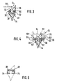
- Figure 3 is an enlarged sectional area of the wiper blade on the line III-III in Figure 1
- Figure 4 one increased wiping area of the wiper blade on the line IV-IV in Figure 1
- the connecting device for the wiper arm is shown in dash-dot lines
- Figure 5 a enlarged view of the support element in the direction of the arrow V in Figure 2, rotated by 90 °.
- a wiper blade 10 shown in FIG. 1 has a multi-part, elongated, spring-elastic support element 12 (Figure 2) on which an elongated, rubber-elastic Wiper strip 14 is fastened parallel to the longitudinal axes.
- a connector 16 arranged, with the help of the wiper blade 10 with a driven, guided on the body of a motor vehicle Wiper arm 18 can be detachably connected.
- a counter-connection means serving hook formed, which one for connecting device 16 of the wiper blade belonging hinge pin 22 embraces.
- the fuse between the wiper arm 18 and the wiper blade 10 is by not shown known securing means designed as adapters accepted.
- the wiper arm 18 and thus the hook at the end of the arm 20 is in the direction of arrow 24 to the window to be wiped loaded, the surface to be wiped in Figure 1 by a dash-dotted line 26 is indicated. Since the dash-dotted Line 26 the strongest curvature of the disc surface is supposed to represent, that the curvature the one with its two ends against the disc Wiper blade is stronger than the maximum window curvature.
- the wiper blade lies under the contact pressure (arrow 24) with its wiper lip 28 along its entire length Disc surface 26 on.
- the band-like, resilient support member 12 a tension, which for proper installation of the wiper strip 14 or Wiper lip 18 over its entire length on the motor vehicle window provides.
- Support element 12 consists of several individual parts. So it has two spring rails 30 and 32, which in the embodiment by adjacent to each other at both ends arranged spring rails placed, clamped or claw-like holding means 34 and 36 connected to each other are. As particularly shown in Figures 3 and 4, each lies of the two spring rails 30 and 32 in one assigned to it Longitudinal groove 38 or 40 of the wiper strip 14, the grooves are arranged in a common plane and thus face each other.
- Figure 2 further shows that both Spring rails 30 and 32 are wider in their central region than in their end areas, because the two outer, from each other lying longitudinal edges 42, 44 run accordingly. The two mutually facing inner longitudinal edges 46, 48 are aligned parallel to each other.
- Figures 3 and 4 further show that the wiper strip 14 with a constriction caused by the longitudinal grooves 38 and 40 50 by the between the two inner longitudinal edges 46 and 48 remaining slot 52 (Figure 2) extends and afterwards, on the side of the Support element 12, widened again and with a substantially triangular cross section is provided as a wind deflector serves.
- the one, mainly the wind (arrow 55 in Figure 3) facing side surface 56 of the wind deflector is grooved like a shovel.
- the second side surface 58 the wind deflector is essentially perpendicular to the Disk 26 aligned and the third side surface 60 of the A wind deflector forms the wall away from the window of the two longitudinal grooves 38 and 40.
- the wiper strip 14 and the wind deflector strip 54 integrated into this in the exemplary embodiment a constant cross-section.
- at least that Cross section of the wind deflector strip 54 over its longitudinal extent seen change.
- the one that stays the same over the length Cross section of the wind deflector strip 54 in the exemplary embodiment does not rule out, however, that this - as in FIG. 1 can be seen - in the central area of the wiper blade 10, the wind deflector strip 54 is interrupted by a recess 62, which leads up to close to the support element 12.
- Recess 62 is the connection device 16 for the wiper arm 18 arranged.
- connection device 16 It reaches over and under the Connection device 16 with legs arranged in pairs 64 and 66 the spring rails 30 and 32 and holds them in their correct position in the longitudinal grooves 38 and 40.
- the legs 64 and 66 are located on cheeks 68 and 70 of the Connection device 16, which by the already mentioned hinge pin 22 are connected.
- the connection device 16 thus also forms a holding means for the two Spring bars 30 and 32.
- the connecting device 16 should but primarily an articulated connection between enable the wiper arm 18 and the wiper blade 10.
- the connecting device 16 takes over also an additional function, namely the backup the spring rail 30 and 32 in the central region.
- the wiper strip 14 can with regard to the different Tasks carried out by the wiper lip 28 or the wind deflector bar 54 must be taken over; for example with help the so-called multi-component extrusion.
Landscapes
- Engineering & Computer Science (AREA)
- Mechanical Engineering (AREA)
- Physics & Mathematics (AREA)
- Fluid Mechanics (AREA)
- Quality & Reliability (AREA)
- Body Structure For Vehicles (AREA)
- Cleaning In General (AREA)
- Seal Device For Vehicle (AREA)
- Springs (AREA)
Description
Bei Wischblättern der im Oberbegriff des Anspruchs 1 bezeichneten Art soll das Tragelement über das gesamte vom Wischblatt bestrichene Wischfeld eine möglichst gleichmäßige Verteilung des Wischerarm ausgehenden Wischblatt-Anpreßdrucks an der Scheibe gewährleisten. Durch eine entsprechende Krümmung des unbelasteten Tragelements - also wenn das Wischblatt nicht an der Scheibe anliegt - werden die Enden der im Betrieb des Wischblatts vollständig an der Scheibe angelegten Wischleiste durch das dann gespannte Tragelement zur Scheibe belastet, auch wenn sich die Krümmungsradien von sphärisch gekrümmten Fahrzeugscheiben bei jeder Wischblattposition ändern. Die Krümmung des Wischblatts muß etwas stärker sein als die im Wischfeld an der zu wischende Scheibe stärkste Krümmung. Das Tragelement ersetzt somit die aufwendige Tragbügelkonstruktion mit zwei in der Wischleiste angeordneten Federschienen, wie sie bei herkömmlichen Wischblättern praktiziert wird (DE-A-15 05 379).For wiper blades referred to in the preamble of claim 1 Art is intended to support the support element over the entire Wiper blade swept the wiping field as evenly as possible Distribution of the wiper arm outgoing wiper blade contact pressure ensure on the disc. By an appropriate Curvature of the unloaded support element - that is if the wiper blade does not touch the window the ends of the wiper blade fully in operation Wiper strip created by the then tensioned support element to the disc, even if the radii of curvature of spherically curved vehicle windows on everyone Change wiper blade position. The curvature of the wiper blade must be slightly stronger than that in the wiping field on the one to be wiped Disc with the greatest curvature. The support element thus replaces the elaborate support bracket construction with two in the wiper strip arranged spring rails, as in conventional Wiper blades are practiced (DE-A-15 05 379).
Die Erfindung geht aus von einem Wischblatt nach der Gattung des Anspruchs 1. Bei einem bekannten Wischblatt dieser Art (DE-C-10 28 896) kann das Wischblatt auf der dem Fahrtwind zugewandeten Vorderseite unter dem Aufbau eines Überdrucks von diesem untergriffen werden. Andererseits baut sich auf der von dem Fahrtwind abgewandten Rückseite ein erheblicher Unterdruck auf. Zwar verändert das im Betrieb meist eine Pendelbewegung ausführende Wischblatt seine Lage in bezug auf den anströmenden Fahrtwind ständig, doch ist auch dann stets seine eine Längsseite diesem mehr oder weniger stark zugewandt und wird deshalb auch als Vorderseite bezeichnet, während seine andere Längsseite demzufolge auch als Rückseite angesehen wird. Im Zusammenwirken dieser beiden vorerwähnten Drucke, die beide dem Wischblatt-Anpreßdruck entgegengerichtet sind, wird dieser bei höheren Fahrgeschwindigkeiten zumindest so verringert, daß kein ordnungsgemäßes Wischergebnis mehr möglich ist. Eine Verstärkung des Wischblatt-Anpreßdrucks gegen die Scheibe mag bei hohen Fahrgeschwindigkeiten zwar dieses Problem verkleinern, doch bei geringeren Fahrgeschwindigkeiten, wenn das Abhebebestreben verringert wird, erhöht sich aber die Reibung zwischen Wischblatt und Scheibe, was zu einer unerwünschten Geräuschbildung und zur unzulässig hohen Belastung der Antriebskomponenten und des Wischgummis führt. Um die erwähnten Abhebebestrebungen des Wischblatts von der Scheibe zu unterdrücken werden im Zubehörhandel sogenannte Spoiler angeboten, welche am Wischblatt-Tragbügelsystem angeordnet werden können. Dies ist bei dem in Rede stehenden Wischblatt aber nicht möglich, weil durch die Befestigung eines solchen in der Regel starren Spoilers am Tragelement dessen Flexibilität praktisch aufgehoben würde, so daß eine ordnungsgemäße Reinigung des vorgeschriebenen Wischfelds nicht mehr möglich wäre.The invention is based on a wiper blade of the type of claim 1. In a known wiper blade of this type (DE-C-10 28 896) the wiper blade on the the head wind facing front under the build-up of overpressure be undermined by this. On the other hand, builds up the rear facing away from the airstream is a considerable one Negative pressure on. This usually changes one in operation The wiper blade executing the pendulum movement relates to its position on the incoming airstream constantly, but even then always its one long side more or less strong facing and is therefore also referred to as the front, while its other long side therefore also serves as the back is seen. In the interaction of these two Prints, both of which oppose the wiper blade contact pressure are, at higher driving speeds at least so reduced that no proper wiping result is more possible. An reinforcement of the Wiper blade contact pressure against the window may be high Driving speeds reduce this problem, but at lower driving speeds, if the attempt to take off is reduced, but increases the friction between Wiper blade and washer, causing undesirable noise and the impermissibly high load on the drive components and the squeegee. To the mentioned The wiper blade is trying to lift off the window suppress so-called spoilers are offered in the accessories trade, which are arranged on the wiper blade support bracket system can be. This is with the wiper blade in question but not possible because of the attachment of such as a rule, rigid spoilers on the support element's flexibility would be practically canceled so that a proper one Cleaning of the prescribed wiping area is no longer possible would.
Bei dem erfindungsgemäßen Wischblatt mit den kennzeichnenden Merkmalen des Anspruchs 1 wird über eine dem Fahrtwind zugewandte Anströmfläche der Windabweisleiste eine zur Scheibe gerichtete Kraftkomponente aufgebaut, welche dem Abhebebestreben der beiden Drucke entgegenwirkt und so für eine hervorragende Reinigungsqualität zumindest in dem für den Fahrzeuglenker wichtigen Bereich des vom Wischblatt überstrichenen Wischfeldes sorgt. Je nach Größe der Anströmfläche kann dieser "Hilfs-Anpreßdruck" den veränderlichen, z.B. vom Fahrzeugtyp abhängigen Forderungen angepaßt werden. Weiter ist es bei der erfindungsgemäßen Lösung von Vorteil, daß der Anpreßdruck als Funktion der Fahrgeschwindigkeit mit dieser ansteigt oder abfällt. Es wird also nur dem bei großer Geschwindigkeit auftretenden störenden Abhebebestreben ein entsprechend großer "Hilfs-Anpreßdruck" entgegengesetzt. Gleichzeitig bieten die aus den Längsnuten der Wischleiste heraustretenden Längskanten der Federschienen eine ausgezeichnete Positionierungs- und Befestigungsmöglichkeit für die Anschlußvorrichtung.In the wiper blade according to the invention with the characteristic Features of claim 1 is the one facing the headwind Flow area of the wind deflector strip one to the pane directed force component built up, which strive to lift off counteracts the two prints and thus for an excellent Cleaning quality at least in that for the vehicle driver important area of the area covered by the wiper blade Wischfeldes cares. Depending on the size of the inflow surface this "auxiliary contact pressure" the variable, e.g. from Vehicle type dependent requirements can be adjusted. Further it is advantageous in the solution according to the invention that the Contact pressure as a function of the driving speed with this rises or falls. So it will only be at high speed disturbing lifting efforts correspondingly large "auxiliary contact pressure" opposite. At the same time, they offer from the longitudinal grooves of the wiper strip emerging longitudinal edges of the spring rails an excellent Positioning and fastening possibility for the connection device.
Wenn die Windabweisleiste in ihrer Längserstreckung zumindest eine bis nahe an die Längsnuten reichende Aussparung aufweist, welche zur Aufnahme von quer zur Längserstreckung angeordneten Haltemitteln für die beiden Federschienen dient, können die Haltemitteln nahe ihren Halte-Ansatzstellen wirksam werden, so daß unerwünschte Hebelwirkungen vermeidbar sind.If the wind deflector at least in its longitudinal extent a recess that extends close to the longitudinal grooves has, which for receiving transversely to the longitudinal extent arranged holding means for the two spring rails serves, the holding means can be close to their holding attachment points take effect so that undesirable leverage are avoidable.
Zweckmäßig hat der als Windabweisleiste ausgebildete Teil der Wischleiste einen im wesentlichen dreieckigen Querschnitt, dessen überwiegend dem Fahrtwind zugewandte Seite schaufelartig gekehlt ist, wobei die zweite Seite der Windabweisleiste im wesentlichen senkrecht zur Scheibe ausgerichtet ist und die dritte Seite, zur Bildung einer kompakt bauenden Windabweisleiste, die eine von der Scheibe abliegende Nutwand für die Federschienen bildet. The part designed as a wind deflector expediently has the wiper strip has an essentially triangular cross section, its predominantly side facing the wind is grooved like a scoop, with the second side of the wind deflector strip aligned substantially perpendicular to the disc is and the third side, to form a compact building wind deflector bar, one lying away from the window Groove wall for the spring rails forms.
Fertigungstechnische Vorteile können sich ergeben, wenn die Wischleiste im wesentlichen über ihre gesamte Längserstrekkung einen gleichbleibenden Querschnitt aufweist.Manufacturing advantages can arise if the Wiper strip essentially over its entire longitudinal extent has a constant cross section.
Zur Stabilisierung des Wischblatts können an dem zum Tragelement gehörenden Federschienen, mehrere über deren Längserstreckung verteilt angeordnete Haltemittel angreifen.To stabilize the wiper blade can on the support element belonging spring rails, several over their longitudinal extent attack holding devices distributed.
In diesem Zusammenhang ergeben sich bei einer Ausbildung der Anschlußvorrichtung als Haltemittel weitere montagetechnische Vorteile.In this context, training results in Connection device as a holding means further assembly technology Benefits.
Eine besonders einfache Form der weiteren Haltemittel ergibt sich, wenn diese als Klammern ausgebildet sind, welche mit Endkrallen die Federschienen an den voneinander abgewandten Längskanten umgreifen.A particularly simple form of the further holding means results itself, if these are designed as brackets, which with End claws on the spring rails facing away from each other Grasp the longitudinal edges.
An den beiden Enden des Wischblatts ergibt sich eine montagefreundliche Möglichkeit der Haltemittel, wenn die Federschienen mit ihren Endabschnitten freiliegen und wenn weiter an diesen Endabschnitten klammerartige Haltemittel angreifen.At the two ends of the wiper blade there is an easy to assemble Possibility of holding means if the spring rails with their end sections exposed and if further engage clamp-like holding means at these end sections.
Weitere vorteilhafte Weiterbildungen und Ausgestaltungen der Erfindung sind in der nachfolgenden Beschreibung eines in der dazu gehörigen Zeichnung dargestellten Ausführungsbeispiels angegeben.Further advantageous developments and refinements of Invention are in the following description of a the associated drawing shown embodiment specified.
In der Zeichnung zeigen Figur 1 eine Seitenansicht eines erfindungsgemäßen Wischblatts, Figur 2 eine unmaßstäbliche Draufsicht auf ein zum Wischblatt gehörendes Tragelement, in das eine Windabweisleiste des Wischblatts strichpunktiert eingezeichnet ist, Figur 3 eine vergrößerte Schnittfläche des Wischblatts an der Linie III-III in Figur 1, Figur 4 eine vergrößerte Wischfläche des Wischblatts an der Linie IV-IV in Figur 1, wobei die Anschlußvorrichtung für den Wischerarm strichpunktiert eingezeichnet ist und Figur 5 eine vergrößerte Ansicht des Tragelements in Richtung des Pfeiles V in Figur 2, um 90° gedreht.In the drawing, Figure 1 shows a side view of an inventive Wiper blade, Figure 2 is an out of scale Top view of a supporting element belonging to the wiper blade, in that dash-dotted a wind deflector strip of the wiper blade is drawn, Figure 3 is an enlarged sectional area of the wiper blade on the line III-III in Figure 1, Figure 4 one increased wiping area of the wiper blade on the line IV-IV in Figure 1, the connecting device for the wiper arm is shown in dash-dot lines and Figure 5 a enlarged view of the support element in the direction of the arrow V in Figure 2, rotated by 90 °.
Ein in Figur 1 dargestelltes Wischblatt 10 weist ein mehrteiliges,
langgestrecktes, federelastisches Tragelement 12
(Figur 2) auf, an dem eine langgestreckte, gummielastische
Wischleiste 14 längsachsenparallel befestigt ist. An der
Oberseite des Tragelements 12 ist eine Anschlußvorrichtung
16 angeordnet, mit deren Hilfe das Wischblatt 10 mit einem
angetriebenen, an der Karosserie eines Kraftfahrzeugs geführten
Wischerarm 18 lösbar verbunden werden kann. An dem
freien Ende 20 des Wischerarms 18 ist ein als Gegenanschlußmittel
dienender Haken angeformt, welcher einen zur Anschlußvorrichtung
16 des Wischblatts gehörenden Gelenkbolzen
22 umgreift. Die Sicherung zwischen dem Wischerarm 18 und
dem Wischblatt 10 wird durch nicht näher dargestellte, an
sich bekannte, als Adapter ausgebildete Sicherungsmittel
übernommen. Der Wischerarm 18 und damit der Haken am Armende
20 ist in Richtung des Pfeiles 24 zur zu wischenden Scheibe
belastet, deren zu wischende Oberfläche in Figur 1 durch eine
strichpunktierte Linie 26 angedeutet ist. Da die strichpunktierte
Linie 26 die stärkste Krümmung der Scheibenoberfläche
darstellen soll, ist klar ersichtlich, daß die Krümmung
des mit seinen beiden Enden an der Scheibe anliegenden
Wischblatts stärker ist als die maximalen Scheibenkrümmung.
Unter dem Anpreßdruck (Pfeil 24) legt sich das Wischblatt
mit seiner Wischlippe 28 über seine gesamte Länge an der
Scheibenoberfläche 26 an. Dabei baut sich im bandartigen,
federelastischen Tragelement 12 eine Spannung auf, welche
für eine ordnungsgemäße Anlage der Wischleiste 14 bzw. der
Wischlippe 18 über deren gesamte Länge an der Kraftfahrzeugscheibe
sorgt.A
Aus Figur 2 ist ersichtlich, daß das dort in Draufsicht dargestellte
Tragelement 12 aus mehreren Einzelteilen besteht.
So weist es zwei Federschienen 30 und 32 auf, die beim Ausführungsbeispiel
durch an den beiden Enden der einander benachbart
angeordneten Federschienen plazierte, klammer- oder
krallenartige Haltemittel 34 und 36 miteinander verbunden
sind. Wie insbesondere die Figuren 3 und 4 zeigen, liegt jede
der beiden Federschienen 30 und 32 in einer ihr zugeordneten
Längsnut 38 bzw. 40 der Wischleiste 14, wobei die Nuten
in einer gemeinsamen Ebene angeordnet sind und somit
einander gegenüberliegen. Weiter zeigt Figur 2, daß beide
Federschienen 30 und 32 in ihrem Mittelbereich breiter sind
als in ihren Endbereichen, weil die beiden äußeren, voneinander
abliegenden Längskanten 42, 44 entsprechend verlaufen.
Die beiden einander zugewandten Innen-Längskanten 46, 48
sind jedoch parallel zueinander ausgerichtet. Diese Innen-Längskanten
46 und 48 liegen am Nutgrund der beiden Längsnuten
38 und 40 an. Da beim Ausführungsbeispiel die Tiefe der
Nuten etwa der Breite der Federschienen 30 und 32 in deren
Endbereichen entspricht, ragen die beiden Federschienen mit
ihren äußeren Längskanten 42 und 44 zum Mittelabschnitt hin
immer weiter aus den Längsnuten 38 und 40 (Figuren 2, 3 und
4).From Figure 2 it can be seen that that shown there in plan
Weiter zeigen die Figuren 3 und 4, daß sich die Wischleiste
14 mit einer durch die Längsnuten 38 und 40 bedingten Einschnürung
50 durch den zwischen den beiden Innen-Längskanten
46 und 48 verbleibenden Schlitz 52 (Figur 2) erstreckt und
sich danach, auf der von der Scheibe abgewandten Seite des
Tragelements 12, wieder verbreitert und mit einem im wesentlichen
dreieckigen Querschnitt versehen ist, der als Windabweisleiste
dient. Die eine, überwiegend dem Fahrtwind (Pfeil
55 in Figur 3) zugewandte Seitenfläche 56 der Windabweisleiste
ist schaufelartig gekehlt. Die zweiten Seitenfläche 58
der Windabweisleiste ist im wesentlichen senkrecht zur
Scheibe 26 ausgerichtet und die dritte Seitenfläche 60 der
Windabweisleiste bildet die von der Scheibe abliegende Wand
der beiden Längsnuten 38 und 40. Wie anhand der gestrichelten
Linie in Figur 2 erkennbar ist, weist die Wischleiste 14
und die in diese integrierte Windabweisleiste 54 beim Ausführungsbeispiel
einen gleichbleibenden Querschnitt auf. Ungeachtet
dessen ist es aber auch denkbar, zumindest den
Querschnitt der Windabweisleiste 54 über deren Längserstrekkung
gesehen zu verändern. Der über die Länge gleichbleibende
Querschnitt der Windabweisleiste 54 beim Ausführungsbeispiel
schließt jedoch nicht aus, daß diese - wie aus Figur 1
ersichtlich - im Mittelbereich des Wischblatts 10 die Windabweisleiste
54 durch eine Aussparung 62 unterbrochen ist,
die bis nahe an das Tragelement 12 heranführt. In dieser
Aussparung 62 ist die Anschlußvorrichtung 16 für den Wischerarm
18 angeordnet. Dabei übergreift und untergreift die
Anschlußvorrichtung 16 mit paarweise angeordneten Schenkeln
64 und 66 die Federschienen 30 und 32 und hält diese in ihrer
vorschriftsmäßigen Position in den Längsnuten 38 und 40.
Die Schenkel 64 und 66 befinden sich an Wangen 68 und 70 der
Anschlußvorrichtung 16, welche durch den schon erwähnten Gelenkbolzen
22 miteinander verbunden sind. Die Anschlußvorrichtung
16 bildet also auch ein Haltemittel für die beiden
Federschienen 30 und 32.Figures 3 and 4 further show that the
Damit die Federschienen 30 und 32 aber auch an ihren Endbereichen
ordnungsgemäß in den Längsnuten 38 und 40 verbleiben,
sind dort weitere, als Klammern 72 ausgebildete Haltemittel
vorgesehen, welche mit Endkrallen 74 (Figur 5) die
Federschienen an ihren voneinander abgewandten Längskanten
42 und 44 umgreifen. Die Figuren 1 und 2 zeigen, daß die Federschienen
30 und 32 mit ihren Endabschnitten aus den
Längsnuten 38 und 40 heraustreten, weil die Windabweisleiste
geringfügig kürzer ist als das Tragelement 12, sodaß an diesen
Endabschnitten die Klammern 74 angreifen können. Bei
entsprechend langen Wischblättern kann es zweckmäßig sein,
weitere, über die Längserstreckung des Wischblatts verteilt
angeordnete krallenartige Haltemittel anzuordnen, denen dann
naturgemäß auch eine Aussparung zugeordnet sein muß, welche
den Durchtritt dieser Klammern durch die Windabweisleiste 54
zulassen.So that the
Aus vorstehendem ist klar ersichtlich, daß zum Tragelement
12 neben den beiden Federschienen 30 und 32 auch Haltemittel
gehören, welche die Sicherung des Tragelements an der Wischleiste
14 gewährleisten. Die Anschlußvorrichtung 16 soll
jedoch in erster Linie eine gelenkige Verbindung zwischen
dem Wischerarm 18 und dem Wischblatt 10 ermöglichen. Darüber
hinaus übernimmt die Anschlußvorrichtung 16, wie schon dargelegt,
auch noch eine zusätzliche Funktion, nämlich die Sicherung
der Federschiene 30 und 32 in deren Mittelbereich.From the above it is clearly evident that the
Die Wischleiste 14 kann mit Rücksicht auf die verschiedenen
Aufgaben, welche von der Wischlippe 28 bzw. der Windabweisleiste
54 übernommen werden müssen; beispielsweise mit Hilfe
der sogenannten Mehrstoffextrusion hergestellt werden.The
Anstelle der separaten Haltemittel 34 und 36 an den Enden
der Federschienen 30 und 32 ist es auch denkbar, diese Haltemittel
als einstückig mit der einen oder auch mit beiden
Federschienen verbundenen, sich zur anderen Federschiene erstreckenden
Querschenkel auszubilden, deren freie Enden zu
Krallen gebogen diese andere Federschiene umgreifen. Es sind
aber auch andere Formen der Befestigung - Kleben, Schweißen
etc. - möglich.Instead of the separate holding means 34 and 36 at the ends
of the
Claims (9)
- Wiper blade (10) for cleaning windows of motor vehicles, having an elongate, elastomeric wiper strip (14) which can be placed against the window and is provided on its two longitudinal sides with respective, mutually opposite longitudinal grooves (38, 40) in which a respective spring rail (30, 32) is provided, which protrudes partially with the one longitudinal edge (42, 44) out of the grooves, the spring rails belonging to an elongate, resilient supporting element (12) for the wiper strip (14) on whose central section is arranged a connecting device (16) for a wiper arm (18) guided on the vehicle bodywork, characterized in that at least one longitudinal section of the part of the wiper strip which is situated on that side of the spring rails (30, 32) which faces away from the window is designed as a wind-deflecting strip (54), and in that the connecting device (16) is held on those longitudinal edges (42, 44) of the spring rails (30, 32) which protrude out of the longitudinal grooves (38, 40).
- Wiper blade according to Claim 1, characterized in that the wind-deflecting strip (54) has, in its longitudinal extent, a cut-out (62) which extends virtually as far as the longitudinal grooves (38, 40) and serves for receiving retaining means, which are arranged transversely to the longitudinal extent, for the two spring rails.
- Wiper blade according to either of Claims 1 and 2, characterized in that that part of the wiper strip (14) which is designed as a wind-deflecting strip (54) has an essentially triangular cross section whose side (56) which predominantly faces the head wind (arrow 55) is moulded in a shovel-like manner.
- Wiper blade according to Claim 3, characterized in that the second side (58) of the wind-deflecting strip (54) is orientated essentially perpendicularly with respect to the window, and in that its third side (60) forms the one groove wall situated away from the window.
- Wiper blade according to one of Claims 1 to 4, characterized in that the wiper strip (14) has a constant cross section essentially over its entire longitudinal extent.
- Wiper blade according to one of Claims 2 to 5, characterized in that a plurality of retaining means (34, 36), which are distributed over the longitudinal extent of the spring rails, act on the spring rails (30, 32), which belong to the supporting element (12).
- Wiper blade according to one of Claims 2 to 6, characterized in that the connecting device (16) is designed as retaining means for the two spring rails (30, 32).
- Wiper blade according to Claim 6, characterized in that the first retaining means (34, 36) are designed as clips (72) which engage with end claws (74) around the spring rails (30, 32) on their mutually remote longitudinal edges (42, 44).
- Wiper blade according to one of Claims 1 to 8, characterized in that the spring rails (32) are exposed at their end sections, and in that clip-like retaining means (34, 36) act on these end sections.
Applications Claiming Priority (3)
| Application Number | Priority Date | Filing Date | Title |
|---|---|---|---|
| DE19739256 | 1997-09-08 | ||
| DE19739256A DE19739256A1 (en) | 1997-09-08 | 1997-09-08 | Wiper blade for cleaning windows of motor vehicles |
| PCT/DE1998/002074 WO1999012784A1 (en) | 1997-09-08 | 1998-07-23 | Wiper blade for cleaning automobile windscreens |
Publications (2)
| Publication Number | Publication Date |
|---|---|
| EP0935546A1 EP0935546A1 (en) | 1999-08-18 |
| EP0935546B1 true EP0935546B1 (en) | 2003-02-05 |
Family
ID=7841566
Family Applications (1)
| Application Number | Title | Priority Date | Filing Date |
|---|---|---|---|
| EP98945037A Expired - Lifetime EP0935546B1 (en) | 1997-09-08 | 1998-07-23 | Wiper blade for cleaning automobile windscreens |
Country Status (9)
| Country | Link |
|---|---|
| US (2) | US6295690B1 (en) |
| EP (1) | EP0935546B1 (en) |
| JP (1) | JP4020978B2 (en) |
| KR (1) | KR100578703B1 (en) |
| BR (1) | BR9806166A (en) |
| DE (2) | DE19739256A1 (en) |
| ES (1) | ES2192333T3 (en) |
| WO (1) | WO1999012784A1 (en) |
| ZA (1) | ZA988136B (en) |
Cited By (5)
| Publication number | Priority date | Publication date | Assignee | Title |
|---|---|---|---|---|
| US8806700B2 (en) | 2011-07-29 | 2014-08-19 | Pylon Manufacturing Corporation | Wiper blade connector |
| US9108595B2 (en) | 2011-07-29 | 2015-08-18 | Pylon Manufacturing Corporation | Windshield wiper connector |
| US9457768B2 (en) | 2011-04-21 | 2016-10-04 | Pylon Manufacturing Corp. | Vortex damping wiper blade |
| US9505380B2 (en) | 2014-03-07 | 2016-11-29 | Pylon Manufacturing Corp. | Windshield wiper connector and assembly |
| USD777079S1 (en) | 2014-10-03 | 2017-01-24 | Pylon Manufacturing Corp. | Wiper blade frame |
Families Citing this family (72)
| Publication number | Priority date | Publication date | Assignee | Title |
|---|---|---|---|---|
| US6874195B2 (en) * | 1997-08-12 | 2005-04-05 | Robert Bosch Gmbh | Wiper blade for windows of motor vehicles |
| DE19739256A1 (en) * | 1997-09-08 | 1999-03-11 | Bosch Gmbh Robert | Wiper blade for cleaning windows of motor vehicles |
| DE19856300A1 (en) * | 1998-12-07 | 2000-06-08 | Bosch Gmbh Robert | Wiper blade for windows of motor vehicles |
| DE19856299A1 (en) * | 1998-12-07 | 2000-06-08 | Bosch Gmbh Robert | Hinged device for connection of wiper blade to windscreens of motor vehicles has wind deflector strip on upper surface of support element that extends on both sides of connecting element in blade's longitudinal direction |
| DE19949887A1 (en) | 1999-10-15 | 2001-04-19 | Volkswagen Ag | Wiper arm |
| DE19957741A1 (en) | 1999-12-01 | 2001-06-07 | Bosch Gmbh Robert | Wiper device for windows of motor vehicles |
| DE19959259B4 (en) * | 1999-12-09 | 2013-01-31 | Volkswagen Ag | Wiper blade for cleaning windows on motor vehicles |
| DE10000381A1 (en) | 2000-01-07 | 2001-11-22 | Valeo Auto Electric Gmbh | Wiper blade for cleaning windows on vehicles, especially motor vehicles |
| DE10014803B4 (en) * | 2000-03-24 | 2017-02-09 | Valeo Auto-Electric Wischer Und Motoren Gmbh | wiper blade |
| EP1244581B1 (en) * | 2000-01-07 | 2003-07-16 | Valeo Wischersysteme GmbH | Wiper device for cleaning the glass panes of vehicles, especially automobiles |
| DE10003589A1 (en) | 2000-01-28 | 2002-04-18 | Volkswagen Ag | Connection device for a wiper blade |
| FR2804922B1 (en) * | 2000-02-11 | 2002-05-03 | Valeo Systemes Dessuyage | WIPER BLADE |
| DE10007800A1 (en) * | 2000-02-21 | 2001-08-23 | Valeo Auto Electric Gmbh | Wiper blade for vehicle windows has cover held on spring rail to cover wiper strip on side facing away from wiper lip |
| DE10011841A1 (en) | 2000-03-10 | 2001-10-11 | Volkswagen Ag | Wiper blade for a windscreen wiper system |
| DE10033779A1 (en) * | 2000-07-12 | 2002-05-02 | Valeo Auto Electric Gmbh | Wiper device, in particular for motor vehicles |
| DE10106874A1 (en) | 2001-02-14 | 2002-09-05 | Volkswagen Ag | Wiper blade for vehicle windows |
| DE10120467A1 (en) * | 2001-04-26 | 2002-10-31 | Bosch Gmbh Robert | Wiper blade for cleaning windows, especially of motor vehicles |
| ES2245340T3 (en) | 2001-05-08 | 2006-01-01 | Federal-Mogul S.A. | WINDSHIELD CLEANING DEVICE. |
| ES2246286T3 (en) * | 2001-05-08 | 2006-02-16 | Federal-Mogul S.A. | WINDSHIELD CLEANING DEVICE. |
| EP1312522B1 (en) * | 2001-11-16 | 2006-06-14 | Federal-Mogul S.A. | Windscreen wiper device comprising a carrier element and a wiper blade |
| DE10259480A1 (en) * | 2002-06-28 | 2004-01-15 | Robert Bosch Gmbh | wiper blade |
| BR0312013A (en) * | 2002-06-28 | 2005-03-22 | Bosch Gmbh Robert | Windscreen Wiper Rubber |
| DE10250553B4 (en) | 2002-10-30 | 2020-07-16 | Robert Bosch Gmbh | Wiper blade, wiper strip and wind deflector |
| US7373688B2 (en) * | 2002-12-13 | 2008-05-20 | Asmo Co., Ltd. | Wiper blade provided with detachable blade rubber and wiper system having the same |
| JP3898186B2 (en) * | 2003-02-14 | 2007-03-28 | ケーシーダブリュー コーポレーション | Wiper blade assembly for vehicle |
| JP4202940B2 (en) * | 2003-06-13 | 2008-12-24 | アスモ株式会社 | Wiper blade |
| ES2289236T3 (en) * | 2003-09-11 | 2008-02-01 | Federal-Mogul S.A. | WINDSHIELD BRUSH. |
| DE102004012867B4 (en) * | 2004-03-16 | 2017-04-06 | Volkswagen Ag | Windscreen wiper for the windscreen wiper system on a vehicle |
| CA2514372A1 (en) * | 2004-07-30 | 2006-01-30 | M Management-Tex, Ltd. | Windshield wiper structure |
| KR100726803B1 (en) * | 2004-11-24 | 2007-06-11 | 박세헌 | Car wipers |
| US20060265830A1 (en) * | 2005-02-14 | 2006-11-30 | Tenneco Automotive Operating Company Inc. | Encapsulated beam with anti-rotation system |
| US7150066B1 (en) | 2005-06-15 | 2006-12-19 | Shih Hsien Huang | Windshield wiper structure for vehicles |
| US20070017056A1 (en) | 2005-07-19 | 2007-01-25 | Cooke Walter W | Wiper blade assembly and method of forming the same |
| US7350259B2 (en) | 2005-07-28 | 2008-04-01 | Tenneco Automotive Operating Company Inc. | Relative axial translation prevention system for wiper blade assemblies |
| US20070022556A1 (en) * | 2005-07-28 | 2007-02-01 | Walworth Van T | Wind deflector with symmetrical geometry |
| TWM288871U (en) * | 2005-09-23 | 2006-03-21 | Shih-Hsien Huang | Special connector for car wiper arm |
| US20070266517A1 (en) * | 2005-10-04 | 2007-11-22 | Adm 21 Co., Ltd | Automotive wiper assembly |
| KR100699187B1 (en) * | 2005-11-30 | 2007-03-23 | 에이디엠이십일 주식회사 | wiper blade |
| KR100813643B1 (en) | 2005-11-30 | 2008-03-14 | 에이디엠이십일 주식회사 | wiper blade |
| KR100733623B1 (en) | 2005-12-05 | 2007-06-29 | 에이디엠이십일 주식회사 | wiper blade |
| DE102006020524A1 (en) * | 2006-05-03 | 2007-11-08 | Robert Bosch Gmbh | wiper blade |
| EP1857336A1 (en) * | 2006-05-16 | 2007-11-21 | Federal-Mogul S.A. | A windscreen wiper device |
| US20080028564A1 (en) * | 2006-08-04 | 2008-02-07 | Shu-Lan Ku | Wiper blade support structure |
| US8122560B2 (en) * | 2006-08-04 | 2012-02-28 | Dongguan Hongyi Wiper Co., Ltd. | Windshield wiper bridge base assembly |
| USD579849S1 (en) * | 2008-03-06 | 2008-11-04 | Rally Manufacturing, Inc. | Windshield wiper |
| KR101098004B1 (en) | 2009-08-26 | 2011-12-22 | 주식회사 캐프 | Multi-adapter of vehicle wiper |
| US8495787B2 (en) | 2010-08-03 | 2013-07-30 | Rally Manufacturing, Inc. | Windshield wiper |
| USD706200S1 (en) | 2010-09-22 | 2014-06-03 | Pylon Manufacturing Corporation | Windshield wiper cover |
| USD685712S1 (en) | 2011-03-23 | 2013-07-09 | Kcw Corporation | Wiper |
| US9174609B2 (en) | 2011-04-21 | 2015-11-03 | Pylon Manufacturing Corp. | Wiper blade with cover |
| FR2977847B1 (en) * | 2011-07-12 | 2014-02-28 | Valeo Systemes Dessuyage | SEMI-RIGID WIPER BLADE WITH RECOVERED SPOILER |
| MX345011B (en) | 2011-07-28 | 2017-01-11 | Pylon Mfg Corp | Windshield wiper adapter, connector and assembly. |
| MX347284B (en) | 2011-07-29 | 2017-04-21 | Pylon Mfg Corp | Windshield wiper connector. |
| US20130219649A1 (en) | 2012-02-24 | 2013-08-29 | Pylon Manufacturing Corp. | Wiper blade |
| MX364943B (en) | 2012-02-24 | 2019-05-14 | Pylon Mfg Corp | Wiper blade. |
| US10723322B2 (en) | 2012-02-24 | 2020-07-28 | Pylon Manufacturing Corp. | Wiper blade with cover |
| US10829092B2 (en) | 2012-09-24 | 2020-11-10 | Pylon Manufacturing Corp. | Wiper blade with modular mounting base |
| US9260083B2 (en) | 2013-01-10 | 2016-02-16 | Scan Top Enterprise Co., Ltd. | Automobile wiper flatly engagable with glass surface |
| ES2626999T3 (en) | 2013-01-10 | 2017-07-26 | Scan Top Enterprise Co. Ltd. | Windshield wiper for motor vehicle that can be fixed horizontally on a glazed surface |
| CN203142626U (en) | 2013-02-07 | 2013-08-21 | 丹阳镇威汽配有限公司 | Sharing type windshield wiper base |
| US10166951B2 (en) | 2013-03-15 | 2019-01-01 | Pylon Manufacturing Corp. | Windshield wiper connector |
| EP2781416B1 (en) | 2013-03-18 | 2015-10-14 | Danyang UPC Auto Parts Co., Ltd. | Wiper connecting apparatus |
| KR101474838B1 (en) | 2013-07-01 | 2014-12-22 | 주식회사 캐프 | A Wiper Blade Assembly |
| KR101608257B1 (en) | 2013-12-05 | 2016-04-11 | 케이씨더블류 주식회사 | Flat wiper blade and combination method |
| GB201409631D0 (en) * | 2014-05-30 | 2014-07-16 | Reckitt Benckiser Brands Ltd | Improved PEI composition |
| USD787308S1 (en) | 2014-10-03 | 2017-05-23 | Pylon Manufacturing Corp. | Wiper blade package |
| US10363905B2 (en) | 2015-10-26 | 2019-07-30 | Pylon Manufacturing Corp. | Wiper blade |
| US10513246B2 (en) | 2016-05-19 | 2019-12-24 | Pylon Manufacturing Corp. | Windshield wiper connector |
| WO2017201473A1 (en) | 2016-05-19 | 2017-11-23 | Pylon Manufacturing Corp. | Windshield wiper blade |
| AU2017267978A1 (en) | 2016-05-19 | 2018-11-22 | Pylon Manufacturing Corp. | Windshield wiper connector |
| WO2017201485A1 (en) | 2016-05-19 | 2017-11-23 | Pylon Manufacturing Corp. | Windshield wiper connector |
| US11040705B2 (en) | 2016-05-19 | 2021-06-22 | Pylon Manufacturing Corp. | Windshield wiper connector |
Family Cites Families (9)
| Publication number | Priority date | Publication date | Assignee | Title |
|---|---|---|---|---|
| DE1028896B (en) * | 1954-06-24 | 1958-04-24 | Avog Elektro Und Feinmechanik | Wiper rail for windshield wiper |
| DE1247161B (en) * | 1962-05-21 | 1967-08-10 | Walter D Appel | Windshield wipers, in particular for motor vehicles |
| DE1505379A1 (en) | 1965-03-25 | 1969-07-31 | Bosch Gmbh Robert | Lighting device for vehicles |
| DE1505397A1 (en) * | 1965-05-07 | 1969-10-30 | Bosch Gmbh Robert | Windshield wipers for vehicles |
| US3317945A (en) * | 1965-09-17 | 1967-05-09 | Hastings Mfg Co | Molded windshield wiper blade |
| GB1429820A (en) * | 1973-12-10 | 1976-03-31 | Trico Folberth Ltd | Windscreen wiper blades |
| DE2839587A1 (en) * | 1978-09-12 | 1980-03-20 | Rau Swf Autozubehoer | Windscreen wiper blade support - includes segmented plastics moulding to even pressure over blade |
| DE19729864A1 (en) * | 1997-07-11 | 1999-01-14 | Bosch Gmbh Robert | Wiper blade for cleaning vehicle windows |
| DE19739256A1 (en) * | 1997-09-08 | 1999-03-11 | Bosch Gmbh Robert | Wiper blade for cleaning windows of motor vehicles |
-
1997
- 1997-09-08 DE DE19739256A patent/DE19739256A1/en not_active Ceased
-
1998
- 1998-07-23 US US09/284,884 patent/US6295690B1/en not_active Expired - Lifetime
- 1998-07-23 JP JP51490099A patent/JP4020978B2/en not_active Expired - Fee Related
- 1998-07-23 DE DE59807118T patent/DE59807118D1/en not_active Expired - Lifetime
- 1998-07-23 BR BR9806166-6A patent/BR9806166A/en not_active IP Right Cessation
- 1998-07-23 KR KR1019997004070A patent/KR100578703B1/en not_active Expired - Fee Related
- 1998-07-23 WO PCT/DE1998/002074 patent/WO1999012784A1/en not_active Ceased
- 1998-07-23 ES ES98945037T patent/ES2192333T3/en not_active Expired - Lifetime
- 1998-07-23 EP EP98945037A patent/EP0935546B1/en not_active Expired - Lifetime
- 1998-09-07 ZA ZA9808136A patent/ZA988136B/en unknown
-
2001
- 2001-02-22 US US09/790,753 patent/US6516491B2/en not_active Expired - Lifetime
Cited By (5)
| Publication number | Priority date | Publication date | Assignee | Title |
|---|---|---|---|---|
| US9457768B2 (en) | 2011-04-21 | 2016-10-04 | Pylon Manufacturing Corp. | Vortex damping wiper blade |
| US8806700B2 (en) | 2011-07-29 | 2014-08-19 | Pylon Manufacturing Corporation | Wiper blade connector |
| US9108595B2 (en) | 2011-07-29 | 2015-08-18 | Pylon Manufacturing Corporation | Windshield wiper connector |
| US9505380B2 (en) | 2014-03-07 | 2016-11-29 | Pylon Manufacturing Corp. | Windshield wiper connector and assembly |
| USD777079S1 (en) | 2014-10-03 | 2017-01-24 | Pylon Manufacturing Corp. | Wiper blade frame |
Also Published As
| Publication number | Publication date |
|---|---|
| EP0935546A1 (en) | 1999-08-18 |
| BR9806166A (en) | 1999-10-19 |
| JP2001504779A (en) | 2001-04-10 |
| KR100578703B1 (en) | 2006-05-12 |
| DE19739256A1 (en) | 1999-03-11 |
| WO1999012784A1 (en) | 1999-03-18 |
| KR20000068926A (en) | 2000-11-25 |
| US6516491B2 (en) | 2003-02-11 |
| ZA988136B (en) | 2000-03-22 |
| JP4020978B2 (en) | 2007-12-12 |
| DE59807118D1 (en) | 2003-03-13 |
| ES2192333T3 (en) | 2003-10-01 |
| US20010008034A1 (en) | 2001-07-19 |
| US6295690B1 (en) | 2001-10-02 |
Similar Documents
| Publication | Publication Date | Title |
|---|---|---|
| EP0935546B1 (en) | Wiper blade for cleaning automobile windscreens | |
| EP0929423B1 (en) | Motor vehicle window wiper | |
| DE19736368B4 (en) | Wiper blade for windows of motor vehicles | |
| EP1037779B1 (en) | Device for connecting a wiper blade for windshields in motor vehicles to a wiper arm | |
| EP0923471B1 (en) | Wiper blade for cleaning vehicle glass panes | |
| EP1053145B1 (en) | Wiper blade for window panes of motor vehicles | |
| EP1547884B1 (en) | Wiper blade for cleaning glass panes, in particular of vehicles | |
| EP0633170B1 (en) | Wiper blade for windscreens of vehicles | |
| EP1501710B1 (en) | Wiper blade | |
| EP1117576A1 (en) | Wiper device for motor vehicle windows comprising a wiper arm which can move between return positions and which is loaded toward the window | |
| DE29712293U1 (en) | Wiper blade for windows of motor vehicles | |
| EP0810936A1 (en) | Wiper blade assembly for motor vehicle windscreens | |
| EP1053143A1 (en) | Device for an articulated connection between a wiper blade for panels of glass in motor vehicles and a wiper arm | |
| EP1289806A1 (en) | Wiper blade for cleaning screens in particular on motor vehicles | |
| EP1337419A1 (en) | Device for detachably connecting a wiper blade for cleaning windows of, in particular, motor vehicles to a driven wiper arm | |
| DE10044913B4 (en) | Wiper blade for cleaning windows, especially motor vehicles | |
| EP0914268B1 (en) | Wiper blade | |
| DE1530993B2 (en) | Wiper blade for vehicle windows | |
| EP0923468A1 (en) | Device for linking a wiper blade to a wiper arm | |
| DE4105406A1 (en) | WIPING DEVICE FOR WINDOWS OF MOTOR VEHICLES | |
| DE69021349T2 (en) | Air guiding device for wiper blade. | |
| DE10312979A1 (en) | Wiper blade for windscreens esp. of motor vehicles has airflow aperture between wiper lip and construction element to deflect air flow | |
| DE102008017250B4 (en) | Noise-dampened wiper blade for a windshield wiper on a vehicle | |
| DE10025722A1 (en) | Wiper blade for cleaning windows, especially of motor vehicles | |
| DE102005024718A1 (en) | wiper blade |
Legal Events
| Date | Code | Title | Description |
|---|---|---|---|
| PUAI | Public reference made under article 153(3) epc to a published international application that has entered the european phase |
Free format text: ORIGINAL CODE: 0009012 |
|
| AK | Designated contracting states |
Kind code of ref document: A1 Designated state(s): BE DE ES FR GB IT |
|
| 17P | Request for examination filed |
Effective date: 19990920 |
|
| GRAG | Despatch of communication of intention to grant |
Free format text: ORIGINAL CODE: EPIDOS AGRA |
|
| 17Q | First examination report despatched |
Effective date: 20020607 |
|
| GRAG | Despatch of communication of intention to grant |
Free format text: ORIGINAL CODE: EPIDOS AGRA |
|
| GRAH | Despatch of communication of intention to grant a patent |
Free format text: ORIGINAL CODE: EPIDOS IGRA |
|
| GRAH | Despatch of communication of intention to grant a patent |
Free format text: ORIGINAL CODE: EPIDOS IGRA |
|
| GRAA | (expected) grant |
Free format text: ORIGINAL CODE: 0009210 |
|
| AK | Designated contracting states |
Designated state(s): BE DE ES FR GB IT |
|
| REG | Reference to a national code |
Ref country code: GB Ref legal event code: FG4D Free format text: NOT ENGLISH |
|
| REF | Corresponds to: |
Ref document number: 59807118 Country of ref document: DE Date of ref document: 20030313 Kind code of ref document: P |
|
| GBT | Gb: translation of ep patent filed (gb section 77(6)(a)/1977) |
Effective date: 20030508 |
|
| ET | Fr: translation filed | ||
| REG | Reference to a national code |
Ref country code: ES Ref legal event code: FG2A Ref document number: 2192333 Country of ref document: ES Kind code of ref document: T3 |
|
| PLBE | No opposition filed within time limit |
Free format text: ORIGINAL CODE: 0009261 |
|
| STAA | Information on the status of an ep patent application or granted ep patent |
Free format text: STATUS: NO OPPOSITION FILED WITHIN TIME LIMIT |
|
| 26N | No opposition filed |
Effective date: 20031106 |
|
| PGFP | Annual fee paid to national office [announced via postgrant information from national office to epo] |
Ref country code: ES Payment date: 20040726 Year of fee payment: 7 |
|
| PG25 | Lapsed in a contracting state [announced via postgrant information from national office to epo] |
Ref country code: IT Free format text: LAPSE BECAUSE OF NON-PAYMENT OF DUE FEES Effective date: 20050723 |
|
| PG25 | Lapsed in a contracting state [announced via postgrant information from national office to epo] |
Ref country code: ES Free format text: LAPSE BECAUSE OF NON-PAYMENT OF DUE FEES Effective date: 20050726 |
|
| REG | Reference to a national code |
Ref country code: ES Ref legal event code: FD2A Effective date: 20050726 |
|
| REG | Reference to a national code |
Ref country code: FR Ref legal event code: PLFP Year of fee payment: 19 |
|
| PGFP | Annual fee paid to national office [announced via postgrant information from national office to epo] |
Ref country code: DE Payment date: 20160927 Year of fee payment: 19 |
|
| REG | Reference to a national code |
Ref country code: FR Ref legal event code: PLFP Year of fee payment: 20 |
|
| PGFP | Annual fee paid to national office [announced via postgrant information from national office to epo] |
Ref country code: GB Payment date: 20170724 Year of fee payment: 20 Ref country code: FR Payment date: 20170720 Year of fee payment: 20 |
|
| PGFP | Annual fee paid to national office [announced via postgrant information from national office to epo] |
Ref country code: BE Payment date: 20170720 Year of fee payment: 20 |
|
| REG | Reference to a national code |
Ref country code: DE Ref legal event code: R119 Ref document number: 59807118 Country of ref document: DE |
|
| PG25 | Lapsed in a contracting state [announced via postgrant information from national office to epo] |
Ref country code: DE Free format text: LAPSE BECAUSE OF NON-PAYMENT OF DUE FEES Effective date: 20180201 |
|
| REG | Reference to a national code |
Ref country code: GB Ref legal event code: PE20 Expiry date: 20180722 |
|
| REG | Reference to a national code |
Ref country code: BE Ref legal event code: MK Effective date: 20180723 |
|
| PG25 | Lapsed in a contracting state [announced via postgrant information from national office to epo] |
Ref country code: GB Free format text: LAPSE BECAUSE OF EXPIRATION OF PROTECTION Effective date: 20180722 |