EP0632306B1 - Brillenscharnier - Google Patents
Brillenscharnier Download PDFInfo
- Publication number
- EP0632306B1 EP0632306B1 EP94108498A EP94108498A EP0632306B1 EP 0632306 B1 EP0632306 B1 EP 0632306B1 EP 94108498 A EP94108498 A EP 94108498A EP 94108498 A EP94108498 A EP 94108498A EP 0632306 B1 EP0632306 B1 EP 0632306B1
- Authority
- EP
- European Patent Office
- Prior art keywords
- housing
- extension
- locking piece
- hinge
- hinge according
- Prior art date
- Legal status (The legal status is an assumption and is not a legal conclusion. Google has not performed a legal analysis and makes no representation as to the accuracy of the status listed.)
- Expired - Lifetime
Links
Images


Classifications
-
- G—PHYSICS
- G02—OPTICS
- G02C—SPECTACLES; SUNGLASSES OR GOGGLES INSOFAR AS THEY HAVE THE SAME FEATURES AS SPECTACLES; CONTACT LENSES
- G02C5/00—Constructions of non-optical parts
- G02C5/22—Hinges
- G02C5/2218—Resilient hinges
- G02C5/2236—Resilient hinges comprising a sliding hinge member and a coil spring
- G02C5/2245—Resilient hinges comprising a sliding hinge member and a coil spring comprising a sliding box containing a spring
-
- G—PHYSICS
- G02—OPTICS
- G02C—SPECTACLES; SUNGLASSES OR GOGGLES INSOFAR AS THEY HAVE THE SAME FEATURES AS SPECTACLES; CONTACT LENSES
- G02C5/00—Constructions of non-optical parts
- G02C5/22—Hinges
- G02C5/2218—Resilient hinges
- G02C5/2236—Resilient hinges comprising a sliding hinge member and a coil spring
-
- G—PHYSICS
- G02—OPTICS
- G02C—SPECTACLES; SUNGLASSES OR GOGGLES INSOFAR AS THEY HAVE THE SAME FEATURES AS SPECTACLES; CONTACT LENSES
- G02C2200/00—Generic mechanical aspects applicable to one or more of the groups G02C1/00 - G02C5/00 and G02C9/00 - G02C13/00 and their subgroups
- G02C2200/30—Piston
Definitions
- the present invention relates to an elastic hinge for spectacles, comprising two parts articulated to one another, a first of these parts being intended to be fixed to the front face of the spectacle frame and the second of these parts comprising a housing provided at the front end of a branch of glasses and an extension slidably mounted in said housing along the longitudinal axis of said housing and subjected to the action of a return spring retained in said housing by a piece of locking engaged at least partially in this housing, the return spring bearing on the one hand on a surface of said extension and on the other hand on the locking piece.
- This type of hinge is known from patent EP 0 201 455 which comprises a locking or closing part having a threaded hole oriented longitudinally. This hole is intended to receive a screw which acts on blocking means, for example in the form of a ball pushed laterally into a cavity to block the closure part in the housing.
- This hinge has a relatively high cost price and requires the production of a threaded bore for the locking screw.
- the assembly of this hinge is quite delicate and long considering that it includes a screwing operation.
- disassembly can be difficult, if not impossible, when the ball is strongly inserted and embedded in the cavity, since it is inaccessible by external intervention.
- the object of the present invention is to remedy these drawbacks and is characterized, to this end, in that the locking piece comprises at least two branches which are integral and substantially perpendicular to each other, a first branch having an elongation substantially parallel to the axis. longitudinal of the housing and a second branch being substantially perpendicular to said longitudinal axis, the housing having a lateral recess, said second branch being arranged so as to engage at least partially in the lateral recess and to retain the return spring, the housing and the first branch being shaped so that the latter is accessible from outside the housing.
- This hinge construction is particularly simple, comprises a very small number of components, and allows a reduced cost price, easy and very rapid assembly and great safety of use, while ensuring rapid disassembly.
- the first branch of the locking piece is constituted by a central portion secured, on the one hand, to the second branch formed by a first lateral portion and, on the other hand, to a second lateral portion, the two lateral portions each having a transverse projection, a first of the lateral portions having a cross section smaller than the opening of the housing and being intended to be introduced into said housing by sliding parallel to the longitudinal axis of the housing, the second said lateral portions having a cross section larger than the opening of the housing so as to abut by its transverse projection against the edge of the opening of said housing, the lateral recess being intended to receive at least partially said transverse projection of the first portion lateral after the positioning of the locking piece by displacement transverse to the axis of the housing, said extension comprising a retaining element capable of cooperating by a first face with the locking piece so as to maintain it in the working position wherein said transverse projection of the first lateral portion is engaged in the lateral recess.
- the second part of the hinge with its extension is shaped so as to maintain the locking piece on the extension by elastic action of the return spring urging the locking piece against a second face of said retaining element , in a mounting position before said extension is introduced in the longitudinal direction in the housing.
- This particular arrangement allows particularly easy mounting of the hinge.
- the assembly constituted by the locking piece, the housing with its digger and the extension with the retaining element is shaped so that, when the extension is introduced into the housing, the locking part pre-mounted on this extension between the return spring and the first face of the retaining element is tilted by action joint of the retaining element and the edge of the housing opposite to this retaining element and so that under the action of the return spring of the locking piece, the latter is moved in a direction transverse to the axis of the housing and that the transverse projection of said first lateral portion penetrates into said recess, the retaining element entering through its first face in contact with the locking piece to hold it in place in the working position of the hinge.
- This arrangement ensures automatic positioning of the locking piece without the use of any tool.
- the retaining element is shaped so as to hold in place by its first face the locking piece with its transverse projection of the first lateral portion engaged in said recess for all the working portions of the hinge and of the branch glasses.
- the hinge therefore has great job security.
- the retaining element and the locking piece are shaped so as to allow disassembly of said extension of the housing by pulling on the extension in a direction parallel to said longitudinal direction so that the locking piece is released from the retaining piece and by transverse displacement of the locking piece.
- This construction allows quick and easy disassembly without reducing the safety of use of the hinge.
- the knuckle having the cam profile is screwed to the extension provided with the second knuckle of the hinge.
- the extension comprises a rod mounted on the second part and carrying the spring which is supported by a first end on an enlarged portion of the rod and by its second end on the locking piece, said second branch comprising a projecting part engaged in the lateral recess and a part shaped so as to at least partially surround the rod to serve as a stop for the second end of the spring mounted on the rod.
- This construction allows a very low cost price, while giving great speed of assembly.
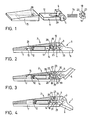
- Figure 1 is a partial view of the various components in exploded perspective of a first embodiment.
- Figures 2 to 4 show sectional views through the hinge of the first embodiment in three different working positions.
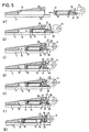
- FIGS 5a) to 5g) illustrate the different phases during assembly of the hinge in accordance with the first embodiment.
- Figure 6 illustrates the disassembly of the hinge according to the first embodiment.
- Figures 7 and 8 are sectional views of two variants of the first embodiment.
- Figure 9 is a partial sectional view through the hinge of a second embodiment.
- FIG. 10 is a perspective view of a detail of FIG. 9.
- Figures 11 a) and 11 c) illustrate the mounting of the hinge according to the second embodiment.
- Figure 12 illustrates the disassembly of the hinge according to the second embodiment.
- the elastic hinge for spectacles shown in FIGS. 1 to 4 comprises two parts 1 and 2 articulated to one another by means of the hinges 3 and 4 secured by the introduction of a screw into the bore 5.
- Part 1 is fixed to the front face 6 of the spectacle frame and the part 2 is made integral with a branch 7 of spectacles by means of a particular elastic mechanism 10.
- the latter comprises an extension 11 of the knuckle 4 having a housing 12 in which is housed a coil spring 14.
- the housing 12 is inserted and slidably retained in a housing 15 integral with the branch of glasses 7.
- the hinge further comprises a locking piece 18 comprising a central portion 19 integral with two lateral portions 20 and 21 each having a transverse projection 22,23.
- the first of the side portions 20 has a cross section smaller than the opening 25 of the housing 15 so that it can be introduced into this housing by sliding parallel to the longitudinal axis 26 of this housing.
- the second lateral portion 21 has a cross section larger than the opening 25 and thus abuts by its transverse projection 23 against the upper edge 27 of the opening 25 of the housing 15.
- a recess 28 is provided in the latter, into which penetrates the transverse projection 22 by displacement transverse to the axis 26 of the housing.
- the second part 2 with its extension 11 is provided with a retaining element 29 in the form of a spacer of rectangular section.
- This spacer cooperates by a first face 30 with the locking piece 18 so as to maintain it in the position illustrated in FIGS. 2 to 4 in which the transverse projection 22 is engaged in the recess 28 and this for all the working positions of the hinge and branch 7 of glasses.
- the assembly constituted by the locking piece 18, the housing 15 with its recess 28 and the extension 11 with the retaining element 22 is shaped so that during the introduction of the extension 11 into the housing 15, the piece of lock 18 pre-assembled on this extension 11 abuts by the transverse projection 23 against the edge 27 of the housing opposite the retaining element 29 (fig. 5c). It is then tilted clockwise in FIG. 5d) by the joint action of the retaining element 29 and the edge 27. Then, when the extension 11 is released, or even slightly withdrawn from the housing 15 (Fig. 5e), the locking piece 18 moves under the action of the spring 14 in a direction transverse to the axis 26 of the housing 15 by tilting counterclockwise so that the transverse projection 22 enters the recess 28. The retaining element 29 then passes below the locking piece 18 under the action of the spring 14 and keeps this piece by its first face 30 in place in the working position of the hinge (fig. 5g).
- the free face 32 of the second lateral portion 23 of the locking piece 18 constitutes a surface support intended to cooperate with the knuckle 3 of the first part 1 of the hinge, which has a cam profile 33 defining by its cooperation with said free face 32 a normal open position (fig. 2) and a folded position of the branch 7 which is resiliently urged against the cam 33 of the front face 6.
- first part 1 with its knuckle 3 can be screwed to knuckle 4 of the extension 11 before the latter is mounted to the branch 7 of glasses. This allows screwing of the elastic hinge without tension between the two knuckles (3,4).
- the free face 32 of the locking piece 18 comprises a hole 35 intended to cooperate with a tool 36 making it possible to move the locking piece perpendicular to the axis of the housing, when its assembly and its extraction.
- the housing 15 includes on its edge an projection 37 covering the edges of the second lateral portion 21 of the locking piece 18, which makes it possible to make invisible all the pieces of the elastic mechanism 10.
- the construction described allows very rapid mounting of the elastic mechanism of the hinge.
- the locking piece 18 is put in place automatically without screwing and at the same time serves as a bearing surface for the cam 33 of the opposite knuckle 3.
- the retaining part 29 has a double retaining function during pre-assembly and assembly.
- the assembly of the two knuckles 3,4 can be carried out without being hampered by the elastic action of the spring 14.
- the second embodiment illustrated in FIGS. 9 to 12 also comprises a part fixed to the front face (not shown) of the spectacle frame and a part 102 made integral with a branch of spectacles 107 by means of an elastic mechanism 110 particular.
- the latter comprises an extension 111 of the knuckle 104 having a piece 113 secured to the knuckle 104 and a screw 116 mounted on the piece 113.
- the extension 111 is slidably disposed in a housing 115 secured to the branch of glasses 107.
- a piece of locking 118 comprises a first portion 119 substantially parallel to the longitudinal axis 126 of the housing 115 and a second portion 120 which is substantially perpendicular thereto.
- This second portion 120 comprises an upper part 123 intended to engage in a recess 128 provided in the wall of the housing 115 and a lower part 124 comprising a general horseshoe shape engaging on the screw 114.
- the elastic mechanism 110 further includes a coil spring 114 mounted on the screw 116 and supported by a first end on the head 117 of the screw 116 and by its second end on the lower part 124 in horseshoe of the second portion 120 of the locking piece 118, thus blocking this end of the spring 114 relative to the wall of the housing 115.
- the face 132 of the housing 115 constitutes a bearing face intended to cooperate with a cam profile of the first part of the hinge, as illustrated in FIG. 2 of the first embodiment.
- Figures 11a), b) and c) illustrate the mounting of the elastic mechanism 110.
- the spring 114 is mounted on the screw 116 and holds the locking piece 118 there temporarily by biasing the lower part 124 in horseshoe of the second portion 120 against the front face 133 of the part 113 of the knuckle 104 which protrudes relative to the screw 116.
- the first portion 119 of the locking part 118 rests on an inclined plane 134 of room 113 (fig. 11a)
- the locking piece 118 thus maintained is introduced into the housing 115 and its upper part 123 slides along a chamfer 135 leading to a horizontal section 136 of the housing 115 (fig. 116), while the lower part 124 in contact with the front face 133 of the part 113 is pushed by this part.
- this locking piece 118 engages there under the effect of the spring 114 and the inclined plane 134 (FIG. 11c)
- the first portion 119 is then applied against the horizontal section 136 of the housing 115.
- the other knuckle may be fixed to the knuckle 104 before or after the introduction of the extension 111 in the housing 115.
- the latter has the shape of a rod having a folded end 137 intended to cooperate with an oblique end face 138 of the first portion 119 of the locking piece 118.
- the embodiments described above have no limiting nature and that they can receive any desirable modifications inside the frame as defined by claim 1.
- the housing 15 may be provided on the front face 6 of the glasses and the knuckle 3 with the cam 33 may be integral with the branch 7.
- the extension 11 may have any other shape provided with a rear surface serving as a support for the spring 14.
- the knuckle 3 may have a different cam 33 with more than two flaps.
Claims (17)
- Elastisches Brillenscharnier mit zwei gelenkig miteinander verbundenen Teilen (1, 2), wobei ein erstes (1) dieser Teile dazu bestimmt ist, an der Vorderseite (1) des Brillengestells befestigt zu werden, und das zweite (2) dieser Teile ein Lager (15; 115), das am vorderen Ende eines Brillenbügels (7; 107) angebracht ist, sowie ein Verlängerungsstück (11; 111) hat, das gleitend in das benannte Lager (15; 115) eingebaut ist, und zwar der Längsachse (26; 126) des benannten Lagers (15; 115) folgend und der Wirkung einer Rückstellfeder (14; 114) unterworfen, die in dem benannten Lager (15; 115) durch eine Verriegelung (18; 118) gehalten wird, die zumindest teilweise in dieses Lager (15; 115) eingefügt ist, wobei die Rückstellfeder (14; 114) einerseits auf einer Fläche des benannten Verlängerungsstücks (11; 111) und andererseits auf der Verriegelung (18; 118) aufliegt, dadurch gekennzeichnet, dass die Verriegelung (18; 118) aus zumindest zwei Armen (19, 22; 119, 120) besteht, die fest miteinander verbunden und zueinander im wesentlichen senkrecht sind, wobei ein erster Arm (19; 119) eine im wesentlichen zur Längsachse (26; 126) des Lagers (15; 115) parallele Verlängerung hat und ein zweiter Arm (22; 120) im wesentlichen senkrecht zu der benannten Längsachse (26; 126) ist, während das Lager eine seitliche Aushöhlung (28; 128) hat und der benannte zweite Arm (22; 122) so eingerichtet ist, dass er zumindest teilweise in die seitliche Aushöhlung (28; 128) einrastet und die Rückstellfeder (14; 114) hält, wobei das Lager (15; 115) und der erste Arm (19; 119) so gestaltet sind, dass letzterer von der Aussenseite des Lagers (15; 115) her zugänglich ist.
- Scharnier gemäss Anspruch 1, dadurch gekennzeichnet, dass der erste Arm der Verriegelung (18) aus einem mittleren Abschnitt (19) besteht, der einerseits mit dem aus einem ersten seitlichen Abschnitt (20) bestehenden zweiten Arm und andererseits mit einem zweiten seitlichen Abschnitt (21) fest verbunden ist, wobei die beiden seitlichen Abschnitte (20, 21) je einen querverlaufenden Vorsprung (22, 23) haben, ein erster (20) der seitlichen Abschnitte einen Querschnitt aufweist, der kleiner als die Öffnung (25) des Lagers (15) ist, und dazu bestimmt ist, parallel zur Längsachse (26) des benannten Lagers (15) gleitend in dieses Lager eingeführt zu werden, und der zweite (21) der benannten seitlichen Abschnitte einen Querschnitt aufweist, der grösser als die Öffnung (25) des Lagers (15) ist, so dass er mit seinem querverlaufenden Vorsprung (23) gegen die Kante (27) der Öffnung (25) des benannten Lagers (15) stösst, während die seitliche Aushöhlung (28) dazu bestimmt ist, nach dem Einsetzen der Verriegelung (18) durch Verschiebung quer zur Achse (26) des Lagers wenigstens teilweise den benannten, querverlaufenden Vorsprung (22) des ersten seitlichen Abschnitts (20) aufzunehmen, und das benannte Verlängerungsstück (11) ein Halteelement (29) hat, das vermittels einer ersten Bahn (30) so mit der Verriegelung (18) zusammenwirken kann, dass diese in ihrer Arbeitsstellung gehalten wird, in der der benannte querverlaufende Vorsprung (22) des ersten seitlichen Abschnitts (20) in die seitliche Aushöhlung (28) eingefügt ist.
- Scharnier gemäss Anspruch 2, dadurch gekennzeichnet, dass das zweite Teil (2) des Scharniers mit seinem Verlängerungsstück (11) so gestaltet ist, dass die Verriegelung (18) durch die elastische Wirkung der Rückstellfeder (14), die die Verriegelung (18) gegen eine zweite Bahn (31) des benannten Halteelements (29) drückt, auf dem Verlängerungsstück (11) gehalten wird, und zwar in einer Montagestellung, bevor das benannte Verlängerungsstück (11) in Längsrichtung in das Lager (15) eingeführt wird.
- Scharnier gemäss Anspruch 2 oder 3, dadurch gekennzeichnet, dass das benannte Verlängerungsstück (11) ein Gehäuse (12) aufweist, worin die Rückstellfeder (14) untergebracht ist.
- Scharnier gemäss Anspruch 4, dadurch gekennzeichnet, dass das Halteelement aus einer Querstrebe (29) rechteckigen Querschnitts besteht, die auf der Seite des benannten Verlängerungsstücks (11) angebracht ist, die der mit der benannten Aushöhlung (28) in Berührung kommenden Seite entgegengesetzt ist.
- Scharnier gemäss einem der Ansprüche 2 bis 5, dadurch gekennzeichnet, dass die aus der Verriegelung (18), dem Lager (15) mit seiner Aushöhlung (28) und dem Verlängerungsstück (11) mit dem Halteelement (29) bestehende Baugruppe so gestaltet ist, dass bei Einführung des Verlängerungsstücks (11) in das Lager (15) die zwischen der Rückstellfeder (14) und der ersten Bahn (31) des Halteelements (29) auf dieses Verlängerungsstück (11) vormontierte Verriegelung (18) durch die gemeinsame Wirkung des Halteelements (29) und der Kante (27) des Lagers (15), die diesem Halteelement (29) gegenüber liegt, so gekippt wird, dass unter der Einwirkung der Rückstellfeder (14) auf die Verriegelung (18) letztere in einer Richtung quer zur Achse (26) des Lagers verschoben wird und dass der querverlaufende Vorsprung (22) des benannten ersten seitlichen Abschnitts (20) in die benannte Aushöhlung (28) eindringt, wobei das Halteelement (29) über seine erste Bahn (30) mit der Verriegelung (18) in Berührung kommt, um sie in der Arbeitsstellung des Scharniers an ihrem Platz zu halten.
- Scharnier gemäss Anspruch 2, dadurch gekennzeichnet, dass die offene Seite (32) des benannten zweiten seitlichen Abschnitts (21) eine Stützfläche darstellt, die dazu bestimmt ist, mit einem Scharnierteil zusammenzuwirken, das mit dem ersten Teil (1) des Scharniers fest verbunden ist, wobei dieses Scharnierteil ein Nockenprofil (33) aufweist, das vermittels seiner Zusammenwirkung mit dem benannten zweiten seitlichen Abschnitt (21) zumindest eine normal geöffnete Stellung und eine zusammengeklappte Stellung des Bügels definiert.
- Scharnier gemäss einem der Ansprüche 2 bis 7, dadurch gekennzeichnet, dass das Lager (15) einen Vorsprung (37) hat, der zumindest teilweise die Kanten des benannten zweiten seitlichen Abschnitts (21) der Verriegelung (18) verdeckt.
- Scharnier gemäss Anspruch 2, dadurch gekennzeichnet, dass der benannte zweite seitliche Abschnitt (21) der Verriegelung (18) auf seiner offenen Seite (32) ein Loch (35) hat, das dazu bestimmt ist, mit einem Werkzeug (36) zusammenzuwirken und zu gestatten, dass die Verriegelung (18) bei ihrem Ein- und Ausbau senkrecht zur Achse (26) des Lagers verschoben wird.
- Scharnier gemäss Anspruch 6, dadurch gekennzeichnet, dass das Halteelement (29) so gestaltet ist, dass es vermittels seiner ersten Bahn (30) die Verriegelung (18) an ihrem Platz hält, während der querverlaufende Vorsprung (22) des ersten seitlichen Abschnitts (20) in allen Arbeitsstellungen des Scharniers und des Brillenbügels (7) in die benannte Aushöhlung (28) eingerastet ist.
- Scharnier gemäss Anspruch 10, dadurch gekennzeichnet, dass das Halteelement (29) und die Verriegelung (18) so gestaltet sind, dass sie es gestatten, dass das benannte Verlängerungsstück (11) des Lagers (15) durch Ziehen am Verlängerungsstück (11) in einer Richtung parallel zu der benannten Längsrichtung, wodurch die Verriegelung (18) aus dem Haltestück (29) ausrastet, und durch Querverschiebung der Verriegelung (18) aus dem Lager (15) ausgebaut wird.
- Scharnier gemäss Ansprüchen 2 bis 6, dadurch gekennzeichnet, dass in der benannten Montagestellung, bevor das Verlängerungsstück (11) in das Lager (15) eingeführt worden ist, das das Nockenprofil (33) aufweisende Scharnierteil auf das mit dem zweiten Scharnierteil des Scharniers versehene Verlängerungsstück (11) aufgeschraubt ist.
- Scharnier gemäss Anspruch 1, dadurch gekennzeichnet, dass das Verlängerungsstück (111) einen Stift (116) aufweist, der auf das zweite Teil montiert ist und die Feder (114) trägt, die mit einem ersten Ende auf einem verbreiterten Abschnitt (117) des Stifts (116) und mit ihrem zweiten Ende auf der Verriegelung (118) ruht, wobei der benannte zweite Arm (120) einen vorspringenden Abschnitt (123), der in die seitliche Aushöhlung (128) eingefügt ist, sowie einen Abschnitt (124) aufweist, der so gestaltet ist, dass er zumindest teilweise den Stift (116) umgibt, um als Anschlag für das zweite Ende der auf den Stift montierten Feder (114) zu dienen.
- Scharnier gemäss Anspruch 13, dadurch gekennzeichnet, dass der erste Arm (119) der Verriegelung (118) an seinem freien Ende eine abgeschrägte Abschlussfläche (138) aufweist, die dazu bestimmt ist, mit einem Werkzeug (141) zusammenzuwirken, um den benannten vorspringenden Abschnitt (123) aus der seitlichen Aushöhlung (128) herauszulösen.
- Scharnier gemäss Anspruch 13, dadurch gekennzeichnet, dass die Verriegelung (118) so gestaltet ist, dass sie in einer Montagestellung, bevor das Verlängerungsstück (111) in das Lager eingeführt worden ist, durch die Wirkung der Rückstellfeder (114), die diese Verriegelung (118) gegen eine Seite (133) des benannten zweiten Teils (102) drückt, auf dem Verlängerungsstück (111) gehalten wird.
- Scharnier gemäss Anspruch 15, dadurch gekennzeichnet, dass das benannte zweite Teil (102) eine Seite (134) aufweist, die bezüglich der benannten Längsachse (126) abgeschrägt ist, und zwar so, dass sich diese abgeschrägte Seite (134) der Verriegelung (118) zu neigt und dazu bestimmt ist, bei Einbau des Verlängerungsstücks (111) in das Lager (115) mit dem ersten Arm (119) zusammenzuwirken.
- Scharnier gemäss Anspruch 15 oder 16, dadurch gekennzeichnet, dass das Lager (115) an seinem offenen Ende eine Abschrägung (135) aufweist, die so gestaltet ist, dass sie mit dem vorspringenden Abschnitt (123) zusammenwirkt, um diesen beim Einbau des Verlängerungsstücks (111) in das Lager (115) zu der seitlichen Aushöhlung (128) hin zu leiten.
Applications Claiming Priority (2)
| Application Number | Priority Date | Filing Date | Title |
|---|---|---|---|
| CH1730/93 | 1993-06-09 | ||
| CH01730/93A CH688666A5 (fr) | 1993-06-09 | 1993-06-09 | Charnière de lunettes. |
Publications (2)
| Publication Number | Publication Date |
|---|---|
| EP0632306A1 EP0632306A1 (de) | 1995-01-04 |
| EP0632306B1 true EP0632306B1 (de) | 1997-12-17 |
Family
ID=4217258
Family Applications (1)
| Application Number | Title | Priority Date | Filing Date |
|---|---|---|---|
| EP94108498A Expired - Lifetime EP0632306B1 (de) | 1993-06-09 | 1994-06-02 | Brillenscharnier |
Country Status (5)
| Country | Link |
|---|---|
| EP (1) | EP0632306B1 (de) |
| AT (1) | ATE161337T1 (de) |
| CH (1) | CH688666A5 (de) |
| DE (1) | DE69407351T2 (de) |
| ES (1) | ES2113015T3 (de) |
Families Citing this family (19)
| Publication number | Priority date | Publication date | Assignee | Title |
|---|---|---|---|---|
| DE4415307C2 (de) * | 1994-04-30 | 1998-02-19 | Obe Werk Kg | Federscharnier für Brillen, mit einem Gehäuse |
| FR2741459B1 (fr) * | 1995-11-16 | 1999-03-26 | Chevassus | Charniere elastique de lunettes a coulisse |
| CH691276A5 (fr) * | 1997-01-29 | 2001-06-15 | Nationale Sa | Charnière élastique. |
| IT1306702B1 (it) * | 1999-04-15 | 2001-10-02 | Visottica Spa | Cerniera elastica per occhiali con blocco di sicurezza. |
| JP3363422B2 (ja) * | 1999-10-27 | 2003-01-08 | オーベーエー オンマフト アンド バウムガルトナー ゲーエムベーハー アンド シーオー.カーゲー | 眼鏡用ばね付きヒンジ |
| WO2003071338A1 (de) * | 2002-02-22 | 2003-08-28 | OBE OHNMACHT & BAUMGäRTNER GMBH & CO. KG | Federscharnier für brillen |
| FR2870010B1 (fr) * | 2004-05-06 | 2006-06-16 | Comotec Sa | Element de charniere elastique compact pour monture de lunettes |
| AT502196B1 (de) * | 2006-02-17 | 2007-02-15 | Redtenbacher Praez Steile Ges | Federscharnier für eine brille |
| FR2907558B1 (fr) | 2006-10-24 | 2009-01-16 | Comotec Sa | Elements de charniere elastique a grande amplitude pour monture de lunettes |
| AT504656B1 (de) | 2007-07-27 | 2008-07-15 | Redtenbacher Praez Steile Ges | Federscharnier für eine brille |
| US8302259B2 (en) | 2008-04-30 | 2012-11-06 | Obe Ohnmacht & Baumgartner Gmbh & Co. Kg | Spring hinge for spectacles |
| DE102008023829A1 (de) * | 2008-05-08 | 2009-11-12 | OBE OHNMACHT & BAUMGäRTNER GMBH & CO. KG | Federscharnier für Brillen |
| EP2344924B1 (de) | 2008-10-06 | 2017-12-13 | Visottica Industrie S. P. A. | Elastisches gelenkelement für brillengestelle |
| FR2938350A1 (fr) * | 2008-11-12 | 2010-05-14 | Comotec | Element de charniere elastique pour monture de lunettes. |
| AT507434B1 (de) * | 2008-11-21 | 2010-05-15 | Redtenbacher Praez Steile Ges | Federscharnier zwischen einem bügelbacken und einem bügel einer brille |
| WO2011103949A1 (de) * | 2010-02-24 | 2011-09-01 | OBE OHNMACHT & BAUMGäRTNER GMBH & CO. KG | Federscharnier |
| JP2011175222A (ja) * | 2010-02-24 | 2011-09-08 | Masami Sakai | 眼鏡用のバネ丁番機構 |
| AT510581B1 (de) * | 2011-02-07 | 2012-05-15 | Redtenbacher Praezisionsteile Ges M B H | Federscharnier für eine brille |
| IT201700121879A1 (it) | 2017-10-26 | 2019-04-26 | Visottica Ind Spa | Cerniera elastica smontabile per montature di occhiali |
Family Cites Families (6)
| Publication number | Priority date | Publication date | Assignee | Title |
|---|---|---|---|---|
| DE3424263C2 (de) * | 1984-06-30 | 1986-08-28 | OBE-Werk Ohnmacht & Baumgärtner GmbH & Co KG, 7536 Ispringen | Federscharnier für Brillen |
| CH664449A5 (fr) * | 1985-05-01 | 1988-02-29 | Nationale Sa | Charniere elastique pour lunettes. |
| DE8905610U1 (de) * | 1989-05-04 | 1990-08-30 | Obe-Werk Ohnmacht & Baumgaertner Gmbh & Co Kg, 7536 Ispringen, De | |
| DE9114193U1 (de) * | 1991-11-14 | 1993-03-11 | Obe-Werk Ohnmacht & Baumgaertner Gmbh & Co Kg, 7536 Ispringen, De | |
| DE9210056U1 (de) * | 1992-07-27 | 1992-09-17 | Obe-Werk Ohnmacht & Baumgaertner Gmbh & Co Kg, 7536 Ispringen, De | |
| DE9301985U1 (de) * | 1993-02-12 | 1993-04-01 | Obe-Werk Ohnmacht & Baumgaertner Gmbh & Co Kg, 7536 Ispringen, De |
-
1993
- 1993-06-09 CH CH01730/93A patent/CH688666A5/fr not_active IP Right Cessation
-
1994
- 1994-06-02 AT AT94108498T patent/ATE161337T1/de not_active IP Right Cessation
- 1994-06-02 DE DE69407351T patent/DE69407351T2/de not_active Expired - Fee Related
- 1994-06-02 EP EP94108498A patent/EP0632306B1/de not_active Expired - Lifetime
- 1994-06-02 ES ES94108498T patent/ES2113015T3/es not_active Expired - Lifetime
Also Published As
| Publication number | Publication date |
|---|---|
| DE69407351D1 (de) | 1998-01-29 |
| DE69407351T2 (de) | 1998-07-23 |
| ES2113015T3 (es) | 1998-04-16 |
| CH688666A5 (fr) | 1997-12-31 |
| EP0632306A1 (de) | 1995-01-04 |
| ATE161337T1 (de) | 1998-01-15 |
Similar Documents
| Publication | Publication Date | Title |
|---|---|---|
| EP0632306B1 (de) | Brillenscharnier | |
| EP2109795B1 (de) | Kompaktes elastisches schwenkglied für brillenrahmen | |
| EP0201455A1 (de) | Federscharnier für Brillen | |
| CH668492A5 (fr) | Monture de lunettes a charnieres elastiques. | |
| CH703093B1 (fr) | Dispositif de commande de verrouillage pour un vantail ouvrant d'huisserie. | |
| EP0715383B1 (de) | Anordnung zur Befestigung eines elektrischen Gerätes an einer Tragschiene | |
| EP0628846B1 (de) | Federscharnier für Brillengestell | |
| WO1999004306A1 (fr) | Charniere elastique pour branche de lunettes plate | |
| EP2832949B1 (de) | Steuerungssystem für die Lamellen von Jalousien, und entsprechende Jalousie | |
| EP0504044A1 (de) | Schrank mit verriegelbarer und umwendbarer Tür, und ein System mit einem solchen Schrank | |
| FR2545139A1 (fr) | Dispositif de securite a action automatique contre les fausses manoeuvres d'une tige de verrouillage equipant un battant de fenetre ou autre | |
| FR2652374A1 (fr) | Poignee pour portiere de vehicule a moteur. | |
| FR2795124A1 (fr) | Ferrure d'articulation invisible pour porte ou fenetre a ouverture a la francaise ou similaire | |
| FR2702573A1 (fr) | Dispositif de verrouillage pour une charnière élastique de lunettes. | |
| EP0940349A1 (de) | Dose bestehend aus lösbaren, schwenkbaren Elementen, insbesondere für Leuchten | |
| EP0504045B1 (de) | Verschlusseinrichtung für eine umwendbare Tür, und Schrank mit dieser Verschlusseinrichtung | |
| FR2776134A1 (fr) | Support d'appareillage a rapporter sur le socle d'une goulotte a retours diriges l'un vers l'autre | |
| EP0531216A1 (de) | Türscharnier mit integriertem Türfeststeller, insbesondere für eine Fahrzeugtür | |
| FR2744849A1 (fr) | Coffret, en particulier coffret electrique, a encastrer dans une cloison | |
| EP0023448A1 (de) | Schloss mit entkuppelbarem Bedienungsdorn | |
| EP1372232A1 (de) | Elektrisches Gehäuse mit gelenkten Schloss | |
| FR2618178A1 (fr) | Double charniere a elements separables, reglables et autobloquants, particulierement pour portes de meubles en general et similaires. | |
| FR2808232A1 (fr) | Dispositif de manutention de moule d'injection | |
| FR2696051A1 (fr) | Armoire à battant de porte équipé d'un détecteur de fermeture. | |
| FR3040946A1 (fr) | Adaptateur pour bras d'essuyage de vehicule automobile |
Legal Events
| Date | Code | Title | Description |
|---|---|---|---|
| PUAI | Public reference made under article 153(3) epc to a published international application that has entered the european phase |
Free format text: ORIGINAL CODE: 0009012 |
|
| AK | Designated contracting states |
Kind code of ref document: A1 Designated state(s): AT DE ES FR GB IT |
|
| 17P | Request for examination filed |
Effective date: 19950508 |
|
| GRAG | Despatch of communication of intention to grant |
Free format text: ORIGINAL CODE: EPIDOS AGRA |
|
| GRAG | Despatch of communication of intention to grant |
Free format text: ORIGINAL CODE: EPIDOS AGRA |
|
| GRAH | Despatch of communication of intention to grant a patent |
Free format text: ORIGINAL CODE: EPIDOS IGRA |
|
| 17Q | First examination report despatched |
Effective date: 19970521 |
|
| GRAH | Despatch of communication of intention to grant a patent |
Free format text: ORIGINAL CODE: EPIDOS IGRA |
|
| GRAA | (expected) grant |
Free format text: ORIGINAL CODE: 0009210 |
|
| AK | Designated contracting states |
Kind code of ref document: B1 Designated state(s): AT DE ES FR GB IT |
|
| REF | Corresponds to: |
Ref document number: 161337 Country of ref document: AT Date of ref document: 19980115 Kind code of ref document: T |
|
| REF | Corresponds to: |
Ref document number: 69407351 Country of ref document: DE Date of ref document: 19980129 |
|
| ITF | It: translation for a ep patent filed |
Owner name: CON LOR S.R.L. |
|
| GBT | Gb: translation of ep patent filed (gb section 77(6)(a)/1977) |
Effective date: 19980318 |
|
| REG | Reference to a national code |
Ref country code: ES Ref legal event code: FG2A Ref document number: 2113015 Country of ref document: ES Kind code of ref document: T3 |
|
| PGFP | Annual fee paid to national office [announced via postgrant information from national office to epo] |
Ref country code: FR Payment date: 19980528 Year of fee payment: 5 |
|
| PGFP | Annual fee paid to national office [announced via postgrant information from national office to epo] |
Ref country code: GB Payment date: 19980529 Year of fee payment: 5 Ref country code: DE Payment date: 19980529 Year of fee payment: 5 |
|
| PGFP | Annual fee paid to national office [announced via postgrant information from national office to epo] |
Ref country code: ES Payment date: 19980602 Year of fee payment: 5 |
|
| PGFP | Annual fee paid to national office [announced via postgrant information from national office to epo] |
Ref country code: AT Payment date: 19980629 Year of fee payment: 5 |
|
| PLBE | No opposition filed within time limit |
Free format text: ORIGINAL CODE: 0009261 |
|
| STAA | Information on the status of an ep patent application or granted ep patent |
Free format text: STATUS: NO OPPOSITION FILED WITHIN TIME LIMIT |
|
| 26N | No opposition filed | ||
| PG25 | Lapsed in a contracting state [announced via postgrant information from national office to epo] |
Ref country code: GB Free format text: LAPSE BECAUSE OF NON-PAYMENT OF DUE FEES Effective date: 19990602 Ref country code: AT Free format text: LAPSE BECAUSE OF NON-PAYMENT OF DUE FEES Effective date: 19990602 |
|
| PG25 | Lapsed in a contracting state [announced via postgrant information from national office to epo] |
Ref country code: ES Free format text: LAPSE BECAUSE OF EXPIRATION OF PROTECTION Effective date: 19990603 |
|
| PG25 | Lapsed in a contracting state [announced via postgrant information from national office to epo] |
Ref country code: FR Free format text: THE PATENT HAS BEEN ANNULLED BY A DECISION OF A NATIONAL AUTHORITY Effective date: 19990630 |
|
| GBPC | Gb: european patent ceased through non-payment of renewal fee |
Effective date: 19990602 |
|
| PG25 | Lapsed in a contracting state [announced via postgrant information from national office to epo] |
Ref country code: DE Free format text: LAPSE BECAUSE OF NON-PAYMENT OF DUE FEES Effective date: 20000503 |
|
| REG | Reference to a national code |
Ref country code: FR Ref legal event code: ST |
|
| REG | Reference to a national code |
Ref country code: ES Ref legal event code: FD2A Effective date: 20010601 |
|
| PG25 | Lapsed in a contracting state [announced via postgrant information from national office to epo] |
Ref country code: IT Free format text: LAPSE BECAUSE OF NON-PAYMENT OF DUE FEES;WARNING: LAPSES OF ITALIAN PATENTS WITH EFFECTIVE DATE BEFORE 2007 MAY HAVE OCCURRED AT ANY TIME BEFORE 2007. THE CORRECT EFFECTIVE DATE MAY BE DIFFERENT FROM THE ONE RECORDED. Effective date: 20050602 |