EP0632306B1 - Spectacle hinge - Google Patents
Spectacle hinge Download PDFInfo
- Publication number
- EP0632306B1 EP0632306B1 EP94108498A EP94108498A EP0632306B1 EP 0632306 B1 EP0632306 B1 EP 0632306B1 EP 94108498 A EP94108498 A EP 94108498A EP 94108498 A EP94108498 A EP 94108498A EP 0632306 B1 EP0632306 B1 EP 0632306B1
- Authority
- EP
- European Patent Office
- Prior art keywords
- housing
- extension
- locking piece
- hinge
- hinge according
- Prior art date
- Legal status (The legal status is an assumption and is not a legal conclusion. Google has not performed a legal analysis and makes no representation as to the accuracy of the status listed.)
- Expired - Lifetime
Links
Images


Classifications
-
- G—PHYSICS
- G02—OPTICS
- G02C—SPECTACLES; SUNGLASSES OR GOGGLES INSOFAR AS THEY HAVE THE SAME FEATURES AS SPECTACLES; CONTACT LENSES
- G02C5/00—Constructions of non-optical parts
- G02C5/22—Hinges
- G02C5/2218—Resilient hinges
- G02C5/2236—Resilient hinges comprising a sliding hinge member and a coil spring
- G02C5/2245—Resilient hinges comprising a sliding hinge member and a coil spring comprising a sliding box containing a spring
-
- G—PHYSICS
- G02—OPTICS
- G02C—SPECTACLES; SUNGLASSES OR GOGGLES INSOFAR AS THEY HAVE THE SAME FEATURES AS SPECTACLES; CONTACT LENSES
- G02C5/00—Constructions of non-optical parts
- G02C5/22—Hinges
- G02C5/2218—Resilient hinges
- G02C5/2236—Resilient hinges comprising a sliding hinge member and a coil spring
-
- G—PHYSICS
- G02—OPTICS
- G02C—SPECTACLES; SUNGLASSES OR GOGGLES INSOFAR AS THEY HAVE THE SAME FEATURES AS SPECTACLES; CONTACT LENSES
- G02C2200/00—Generic mechanical aspects applicable to one or more of the groups G02C1/00 - G02C5/00 and G02C9/00 - G02C13/00 and their subgroups
- G02C2200/30—Piston
Definitions
- the present invention relates to an elastic hinge for spectacles, comprising two parts articulated to one another, a first of these parts being intended to be fixed to the front face of the spectacle frame and the second of these parts comprising a housing provided at the front end of a branch of glasses and an extension slidably mounted in said housing along the longitudinal axis of said housing and subjected to the action of a return spring retained in said housing by a piece of locking engaged at least partially in this housing, the return spring bearing on the one hand on a surface of said extension and on the other hand on the locking piece.
- This type of hinge is known from patent EP 0 201 455 which comprises a locking or closing part having a threaded hole oriented longitudinally. This hole is intended to receive a screw which acts on blocking means, for example in the form of a ball pushed laterally into a cavity to block the closure part in the housing.
- This hinge has a relatively high cost price and requires the production of a threaded bore for the locking screw.
- the assembly of this hinge is quite delicate and long considering that it includes a screwing operation.
- disassembly can be difficult, if not impossible, when the ball is strongly inserted and embedded in the cavity, since it is inaccessible by external intervention.
- the object of the present invention is to remedy these drawbacks and is characterized, to this end, in that the locking piece comprises at least two branches which are integral and substantially perpendicular to each other, a first branch having an elongation substantially parallel to the axis. longitudinal of the housing and a second branch being substantially perpendicular to said longitudinal axis, the housing having a lateral recess, said second branch being arranged so as to engage at least partially in the lateral recess and to retain the return spring, the housing and the first branch being shaped so that the latter is accessible from outside the housing.
- This hinge construction is particularly simple, comprises a very small number of components, and allows a reduced cost price, easy and very rapid assembly and great safety of use, while ensuring rapid disassembly.
- the first branch of the locking piece is constituted by a central portion secured, on the one hand, to the second branch formed by a first lateral portion and, on the other hand, to a second lateral portion, the two lateral portions each having a transverse projection, a first of the lateral portions having a cross section smaller than the opening of the housing and being intended to be introduced into said housing by sliding parallel to the longitudinal axis of the housing, the second said lateral portions having a cross section larger than the opening of the housing so as to abut by its transverse projection against the edge of the opening of said housing, the lateral recess being intended to receive at least partially said transverse projection of the first portion lateral after the positioning of the locking piece by displacement transverse to the axis of the housing, said extension comprising a retaining element capable of cooperating by a first face with the locking piece so as to maintain it in the working position wherein said transverse projection of the first lateral portion is engaged in the lateral recess.
- the second part of the hinge with its extension is shaped so as to maintain the locking piece on the extension by elastic action of the return spring urging the locking piece against a second face of said retaining element , in a mounting position before said extension is introduced in the longitudinal direction in the housing.
- This particular arrangement allows particularly easy mounting of the hinge.
- the assembly constituted by the locking piece, the housing with its digger and the extension with the retaining element is shaped so that, when the extension is introduced into the housing, the locking part pre-mounted on this extension between the return spring and the first face of the retaining element is tilted by action joint of the retaining element and the edge of the housing opposite to this retaining element and so that under the action of the return spring of the locking piece, the latter is moved in a direction transverse to the axis of the housing and that the transverse projection of said first lateral portion penetrates into said recess, the retaining element entering through its first face in contact with the locking piece to hold it in place in the working position of the hinge.
- This arrangement ensures automatic positioning of the locking piece without the use of any tool.
- the retaining element is shaped so as to hold in place by its first face the locking piece with its transverse projection of the first lateral portion engaged in said recess for all the working portions of the hinge and of the branch glasses.
- the hinge therefore has great job security.
- the retaining element and the locking piece are shaped so as to allow disassembly of said extension of the housing by pulling on the extension in a direction parallel to said longitudinal direction so that the locking piece is released from the retaining piece and by transverse displacement of the locking piece.
- This construction allows quick and easy disassembly without reducing the safety of use of the hinge.
- the knuckle having the cam profile is screwed to the extension provided with the second knuckle of the hinge.
- the extension comprises a rod mounted on the second part and carrying the spring which is supported by a first end on an enlarged portion of the rod and by its second end on the locking piece, said second branch comprising a projecting part engaged in the lateral recess and a part shaped so as to at least partially surround the rod to serve as a stop for the second end of the spring mounted on the rod.
- This construction allows a very low cost price, while giving great speed of assembly.
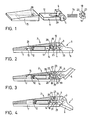
- Figure 1 is a partial view of the various components in exploded perspective of a first embodiment.
- Figures 2 to 4 show sectional views through the hinge of the first embodiment in three different working positions.
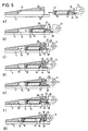
- FIGS 5a) to 5g) illustrate the different phases during assembly of the hinge in accordance with the first embodiment.
- Figure 6 illustrates the disassembly of the hinge according to the first embodiment.
- Figures 7 and 8 are sectional views of two variants of the first embodiment.
- Figure 9 is a partial sectional view through the hinge of a second embodiment.
- FIG. 10 is a perspective view of a detail of FIG. 9.
- Figures 11 a) and 11 c) illustrate the mounting of the hinge according to the second embodiment.
- Figure 12 illustrates the disassembly of the hinge according to the second embodiment.
- the elastic hinge for spectacles shown in FIGS. 1 to 4 comprises two parts 1 and 2 articulated to one another by means of the hinges 3 and 4 secured by the introduction of a screw into the bore 5.
- Part 1 is fixed to the front face 6 of the spectacle frame and the part 2 is made integral with a branch 7 of spectacles by means of a particular elastic mechanism 10.
- the latter comprises an extension 11 of the knuckle 4 having a housing 12 in which is housed a coil spring 14.
- the housing 12 is inserted and slidably retained in a housing 15 integral with the branch of glasses 7.
- the hinge further comprises a locking piece 18 comprising a central portion 19 integral with two lateral portions 20 and 21 each having a transverse projection 22,23.
- the first of the side portions 20 has a cross section smaller than the opening 25 of the housing 15 so that it can be introduced into this housing by sliding parallel to the longitudinal axis 26 of this housing.
- the second lateral portion 21 has a cross section larger than the opening 25 and thus abuts by its transverse projection 23 against the upper edge 27 of the opening 25 of the housing 15.
- a recess 28 is provided in the latter, into which penetrates the transverse projection 22 by displacement transverse to the axis 26 of the housing.
- the second part 2 with its extension 11 is provided with a retaining element 29 in the form of a spacer of rectangular section.
- This spacer cooperates by a first face 30 with the locking piece 18 so as to maintain it in the position illustrated in FIGS. 2 to 4 in which the transverse projection 22 is engaged in the recess 28 and this for all the working positions of the hinge and branch 7 of glasses.
- the assembly constituted by the locking piece 18, the housing 15 with its recess 28 and the extension 11 with the retaining element 22 is shaped so that during the introduction of the extension 11 into the housing 15, the piece of lock 18 pre-assembled on this extension 11 abuts by the transverse projection 23 against the edge 27 of the housing opposite the retaining element 29 (fig. 5c). It is then tilted clockwise in FIG. 5d) by the joint action of the retaining element 29 and the edge 27. Then, when the extension 11 is released, or even slightly withdrawn from the housing 15 (Fig. 5e), the locking piece 18 moves under the action of the spring 14 in a direction transverse to the axis 26 of the housing 15 by tilting counterclockwise so that the transverse projection 22 enters the recess 28. The retaining element 29 then passes below the locking piece 18 under the action of the spring 14 and keeps this piece by its first face 30 in place in the working position of the hinge (fig. 5g).
- the free face 32 of the second lateral portion 23 of the locking piece 18 constitutes a surface support intended to cooperate with the knuckle 3 of the first part 1 of the hinge, which has a cam profile 33 defining by its cooperation with said free face 32 a normal open position (fig. 2) and a folded position of the branch 7 which is resiliently urged against the cam 33 of the front face 6.
- first part 1 with its knuckle 3 can be screwed to knuckle 4 of the extension 11 before the latter is mounted to the branch 7 of glasses. This allows screwing of the elastic hinge without tension between the two knuckles (3,4).
- the free face 32 of the locking piece 18 comprises a hole 35 intended to cooperate with a tool 36 making it possible to move the locking piece perpendicular to the axis of the housing, when its assembly and its extraction.
- the housing 15 includes on its edge an projection 37 covering the edges of the second lateral portion 21 of the locking piece 18, which makes it possible to make invisible all the pieces of the elastic mechanism 10.
- the construction described allows very rapid mounting of the elastic mechanism of the hinge.
- the locking piece 18 is put in place automatically without screwing and at the same time serves as a bearing surface for the cam 33 of the opposite knuckle 3.
- the retaining part 29 has a double retaining function during pre-assembly and assembly.
- the assembly of the two knuckles 3,4 can be carried out without being hampered by the elastic action of the spring 14.
- the second embodiment illustrated in FIGS. 9 to 12 also comprises a part fixed to the front face (not shown) of the spectacle frame and a part 102 made integral with a branch of spectacles 107 by means of an elastic mechanism 110 particular.
- the latter comprises an extension 111 of the knuckle 104 having a piece 113 secured to the knuckle 104 and a screw 116 mounted on the piece 113.
- the extension 111 is slidably disposed in a housing 115 secured to the branch of glasses 107.
- a piece of locking 118 comprises a first portion 119 substantially parallel to the longitudinal axis 126 of the housing 115 and a second portion 120 which is substantially perpendicular thereto.
- This second portion 120 comprises an upper part 123 intended to engage in a recess 128 provided in the wall of the housing 115 and a lower part 124 comprising a general horseshoe shape engaging on the screw 114.
- the elastic mechanism 110 further includes a coil spring 114 mounted on the screw 116 and supported by a first end on the head 117 of the screw 116 and by its second end on the lower part 124 in horseshoe of the second portion 120 of the locking piece 118, thus blocking this end of the spring 114 relative to the wall of the housing 115.
- the face 132 of the housing 115 constitutes a bearing face intended to cooperate with a cam profile of the first part of the hinge, as illustrated in FIG. 2 of the first embodiment.
- Figures 11a), b) and c) illustrate the mounting of the elastic mechanism 110.
- the spring 114 is mounted on the screw 116 and holds the locking piece 118 there temporarily by biasing the lower part 124 in horseshoe of the second portion 120 against the front face 133 of the part 113 of the knuckle 104 which protrudes relative to the screw 116.
- the first portion 119 of the locking part 118 rests on an inclined plane 134 of room 113 (fig. 11a)
- the locking piece 118 thus maintained is introduced into the housing 115 and its upper part 123 slides along a chamfer 135 leading to a horizontal section 136 of the housing 115 (fig. 116), while the lower part 124 in contact with the front face 133 of the part 113 is pushed by this part.
- this locking piece 118 engages there under the effect of the spring 114 and the inclined plane 134 (FIG. 11c)
- the first portion 119 is then applied against the horizontal section 136 of the housing 115.
- the other knuckle may be fixed to the knuckle 104 before or after the introduction of the extension 111 in the housing 115.
- the latter has the shape of a rod having a folded end 137 intended to cooperate with an oblique end face 138 of the first portion 119 of the locking piece 118.
- the embodiments described above have no limiting nature and that they can receive any desirable modifications inside the frame as defined by claim 1.
- the housing 15 may be provided on the front face 6 of the glasses and the knuckle 3 with the cam 33 may be integral with the branch 7.
- the extension 11 may have any other shape provided with a rear surface serving as a support for the spring 14.
- the knuckle 3 may have a different cam 33 with more than two flaps.
Abstract
Description
La présente invention a pour objet une charnière élastique pour lunettes, comprenant deux parties articulées l'une à l'autre, une première de ces parties étant destinée à être fixée à la face frontale de la monture de lunettes et la seconde de ces parties comportant un logement prévu à l'extrémité avant d'une branche de lunettes et un prolongement monté en coulissement dans ledit logement suivant l'axe longitudinal dudit logement et soumis à l'action d'un ressort de rappel retenu dans ledit logement par une pièce de verrouillage engagée au moins partiellement dans ce logement, le ressort de rappel prenant appui d'une part sur une surface dudit prolongement et d'autre part sur la pièce de verrouillage.The present invention relates to an elastic hinge for spectacles, comprising two parts articulated to one another, a first of these parts being intended to be fixed to the front face of the spectacle frame and the second of these parts comprising a housing provided at the front end of a branch of glasses and an extension slidably mounted in said housing along the longitudinal axis of said housing and subjected to the action of a return spring retained in said housing by a piece of locking engaged at least partially in this housing, the return spring bearing on the one hand on a surface of said extension and on the other hand on the locking piece.
On connaît ce genre de charnière par le brevet EP 0 201 455 qui comprend une pièce de verrouillage ou de fermeture présentant un trou fileté orienté longitudinalement. Ce trou est destiné à recevoir une vis qui agit sur des moyens de blocage, par exemple sous forme d'une bille poussée latéralement dans une cavité pour bloquer la pièce de fermeture dans le logement.This type of hinge is known from patent EP 0 201 455 which comprises a locking or closing part having a threaded hole oriented longitudinally. This hole is intended to receive a screw which acts on blocking means, for example in the form of a ball pushed laterally into a cavity to block the closure part in the housing.
Cette charnière est d'un prix de revient relativement élevé et nécessite la confection d'un alésage fileté pour la vis de blocage. Le montage de cette charnière est assez délicat et long considérant qu'il comprend une opération de vissage. En outre, le démontage peut être difficile, voire impossible, lorsque la bille est fortement insérée et encastrée dans la cavité, étant donné qu'elle est inaccessible par une intervention extérieure.This hinge has a relatively high cost price and requires the production of a threaded bore for the locking screw. The assembly of this hinge is quite delicate and long considering that it includes a screwing operation. In addition, disassembly can be difficult, if not impossible, when the ball is strongly inserted and embedded in the cavity, since it is inaccessible by external intervention.
La présente invention a pour but de remédier à ces inconvénients et est caractérisée, à cet effet, en ce que la pièce de verrouillage comporte au moins deux branches solidaires et sensiblement perpendiculaire entre elles, une première branche possédant un allongement sensiblement parallèle à l'axe longitudinal du logement et une seconde branche étant sensiblement perpendiculaire audit axe longitudinal, le logement présentant une creusure latérale, ladite deuxième branche étant agencée de manière à s'engager au moins partiellement dans la creusure latérale et à retenir le ressort de rappel, le logement et la première branche étant conformés de façon que cette dernière soit accessible de l'extérieur du logement.The object of the present invention is to remedy these drawbacks and is characterized, to this end, in that the locking piece comprises at least two branches which are integral and substantially perpendicular to each other, a first branch having an elongation substantially parallel to the axis. longitudinal of the housing and a second branch being substantially perpendicular to said longitudinal axis, the housing having a lateral recess, said second branch being arranged so as to engage at least partially in the lateral recess and to retain the return spring, the housing and the first branch being shaped so that the latter is accessible from outside the housing.
Cette construction de charnière est particulièrement simple, comprend un très petit nombre de composants, et permet un prix de revient réduit, un montage aisé et très rapide et une grande sécurité d'utilisation, tout en assurant un démontage rapide.This hinge construction is particularly simple, comprises a very small number of components, and allows a reduced cost price, easy and very rapid assembly and great safety of use, while ensuring rapid disassembly.
Dans un mode d'exécution préféré, la première branche de la pièce de verrouillage est constituée par une portion centrale solidaire, d'une part, de la deuxième branche constituée par une première portion latérale et, d'autre part, d'une seconde portion latérale, les deux portions latérales présentant chacune une saillie transversale, une première des portions latérales présentant une section droite plus petite que l'ouverture du logement et étant destinée à être introduite dans ledit logement par coulissement parallèle à l'axe longitudinal du logement, la seconde desdites portions latérales présentant une section droite plus grande que l'ouverture du logement de façon à buter par sa saillie transversale contre le bord de l'ouverture dudit logement, la creusure latérale étant destinée à recevoir au moins partiellement ladite saillie transversale de la première portion latérale après la mise en place de la pièce de verrouillage par déplacement transversal à l'axe du logement, ledit prolongement comportant un élément de retenue susceptible de coopérer par une première face avec la pièce de verrouillage de façon à la maintenir dans la position de travail dans laquelle ladite saillie transversale de la première portion latérale est engagée dans la creusure latérale.In a preferred embodiment, the first branch of the locking piece is constituted by a central portion secured, on the one hand, to the second branch formed by a first lateral portion and, on the other hand, to a second lateral portion, the two lateral portions each having a transverse projection, a first of the lateral portions having a cross section smaller than the opening of the housing and being intended to be introduced into said housing by sliding parallel to the longitudinal axis of the housing, the second said lateral portions having a cross section larger than the opening of the housing so as to abut by its transverse projection against the edge of the opening of said housing, the lateral recess being intended to receive at least partially said transverse projection of the first portion lateral after the positioning of the locking piece by displacement transverse to the axis of the housing, said extension comprising a retaining element capable of cooperating by a first face with the locking piece so as to maintain it in the working position wherein said transverse projection of the first lateral portion is engaged in the lateral recess.
Selon un mode d'exécution avantageux, la seconde partie de la charnière avec son prolongement est conformée de façon à maintenir la pièce de verrouillage sur le prolongement par action élastique du ressort de rappel sollicitant la pièce de verrouillage contre une seconde face dudit élément de retenue, dans une position de montage avant que ledit prolongement soit introduit suivant le sens longitudinal dans le logement.According to an advantageous embodiment, the second part of the hinge with its extension is shaped so as to maintain the locking piece on the extension by elastic action of the return spring urging the locking piece against a second face of said retaining element , in a mounting position before said extension is introduced in the longitudinal direction in the housing.
Cette disposition particulière permet un montage particulièrement aisé de la charnière.This particular arrangement allows particularly easy mounting of the hinge.
Selon un mode d'exécution préféré, l'ensemble constitué par la pièce de verrouillage, le logement avec sa creuseure et le prolongement avec l'élément de retenue est conformé de façon que, lors de l'introduction du prolongement dans le logement, la pièce de verrouillage prémontée sur ce prolongement entre le ressort de rappel et la première face de l'élément de retenue soit basculée par action conjointe de l'élément de retenue et du bord du logement opposé à cet élément de retenue et de façon que sous l'action du ressort de rappel de la pièce de verrouillage, cette dernière soit déplacée suivant une direction transversale à l'axe du logement et que la saillie transversale de ladite première portion latérale pénètre dans ladite creusure, l'élément de retenue entrant par sa première face en contact avec la pièce de verrouillage pour la maintenir en place dans la position de travail de la charnière.According to a preferred embodiment, the assembly constituted by the locking piece, the housing with its digger and the extension with the retaining element is shaped so that, when the extension is introduced into the housing, the locking part pre-mounted on this extension between the return spring and the first face of the retaining element is tilted by action joint of the retaining element and the edge of the housing opposite to this retaining element and so that under the action of the return spring of the locking piece, the latter is moved in a direction transverse to the axis of the housing and that the transverse projection of said first lateral portion penetrates into said recess, the retaining element entering through its first face in contact with the locking piece to hold it in place in the working position of the hinge.
Cette disposition assure une mise en place automatique de la pièce de verrouillage sans utilisation d'un outil quelconque.This arrangement ensures automatic positioning of the locking piece without the use of any tool.
De préférence, l'élément de retenue est conformé de façon à maintenir en place par sa première face la pièce de verrouillage avec sa saillie transversale de la première portion latérale engagée dans ladite creusure pour toutes les portions de travail de la charnière et de la branche de lunettes.Preferably, the retaining element is shaped so as to hold in place by its first face the locking piece with its transverse projection of the first lateral portion engaged in said recess for all the working portions of the hinge and of the branch glasses.
La charnière présente de ce fait une grande sécurité d'emploi.The hinge therefore has great job security.
Avantageusement, l'élément de retenue et la pièce de verrouillage sont conformés de façon à permettre un démontage dudit prolongement du logement par traction sur le prolongement suivant un sens parallèle audit sens longidutinal pour que la pièce de verrouillage soit dégagée de la pièce de retenue et par déplacement transversal de la pièce de verrouillage.Advantageously, the retaining element and the locking piece are shaped so as to allow disassembly of said extension of the housing by pulling on the extension in a direction parallel to said longitudinal direction so that the locking piece is released from the retaining piece and by transverse displacement of the locking piece.
Cette construction permet un démontage rapide et aisé sans pour autant diminuer la sécurité d'emploi de la charnière.This construction allows quick and easy disassembly without reducing the safety of use of the hinge.
De préférence, dans ladite position de montage, avant que le prolongement ne soit introduit dans le logement, le charnon présentant le profil de came est vissé au prolongement muni du second charnon de la charnière.Preferably, in said mounting position, before the extension is introduced into the housing, the knuckle having the cam profile is screwed to the extension provided with the second knuckle of the hinge.
L'assemblage du pivot de la charnière est ainsi facilité, car les deux parties de la charnière ne sont pas sous tension.The assembly of the hinge pivot is thus facilitated, since the two parts of the hinge are not under tension.
Dans un autre mode d'exécution avantageux, le prolongement comprend une tige montée sur la seconde partie et portant le ressort qui s'appuie par une première extrémité sur une portion élargie de la tige et par sa deuxième extrémité sur la pièce de verrouillage, ladite seconde branche comportant une partie en saillie engagée dans la creusure latérale et une partie conformée de façon à entourer au moins partiellement la tige pour servir de butée pour la deuxième extrémité du ressort monté sur la tige.In another advantageous embodiment, the extension comprises a rod mounted on the second part and carrying the spring which is supported by a first end on an enlarged portion of the rod and by its second end on the locking piece, said second branch comprising a projecting part engaged in the lateral recess and a part shaped so as to at least partially surround the rod to serve as a stop for the second end of the spring mounted on the rod.
Cette constuction permet un prix de revient très faible, tout en conférant une grande rapidité de montage.This construction allows a very low cost price, while giving great speed of assembly.
D'autres avantages ressortent des caractéristiques exprimées dans les revendications dépendantes et de la description exposant ci-après l'invention plus en détail à l'aide de dessins qui représentent schématiquement et à titre d'exemple deux modes d'exécution et des variantes.Other advantages emerge from the characteristics expressed in the dependent claims and from the description setting out the invention below in more detail with the aid of drawings which schematically represent by way of example two embodiments and variants.
La figure 1 est une vue partielle des différents composants en perspective éclatée d'un premier mode d'exécution.Figure 1 is a partial view of the various components in exploded perspective of a first embodiment.
Les figures 2 à 4 représentent des vues en coupe à travers la charnière du premier mode d'exécution dans trois positions différentes de travail.Figures 2 to 4 show sectional views through the hinge of the first embodiment in three different working positions.
Les figures 5a) à 5g) illustrent les différentes phases lors du montage de la charnière conformément au premier mode d'exécution.Figures 5a) to 5g) illustrate the different phases during assembly of the hinge in accordance with the first embodiment.
La figure 6 illustre le démontage de la charnière conformément au premier mode d'exécution.Figure 6 illustrates the disassembly of the hinge according to the first embodiment.
Les figures 7 et 8 sont des vues en coupe de deux variantes du premier mode d'exécution.Figures 7 and 8 are sectional views of two variants of the first embodiment.
La figure 9 est une vue en coupe partielle à travers la charnière d'un second mode d'exécution.Figure 9 is a partial sectional view through the hinge of a second embodiment.
La figure 10 est une vue en perspective d'un détail de la figure 9.FIG. 10 is a perspective view of a detail of FIG. 9.
Les figures 11 a) et 11 c) illustrent le montage de la charnière conformément au second mode d'exécution.Figures 11 a) and 11 c) illustrate the mounting of the hinge according to the second embodiment.
La figure 12 illustre le démontage de la charnière conformément au second mode d'exécution.Figure 12 illustrates the disassembly of the hinge according to the second embodiment.
La charnière élastique pour lunettes représentée aux figures 1 à 4 comprend deux parties 1 et 2 articulées l'une à l'autre grâce aux charnons 3 et 4 solidarisés par l'introduction d'une vis dans l'alésage 5. La partie 1 est fixée à la face frontale 6 de la monture de lunettes et la partie 2 est rendue solidaire d'une branche 7 de lunettes au moyen d'un mécanisme élastique 10 particulier. Ce dernier comprend un prolongement 11 du charnon 4 présentant un boîtier 12 dans lequel est logé un ressort à boudin 14. Le boîtier 12 est inséré et retenu de façon coulissante dans un logement 15 solidaire de la branche de lunettes 7. La charnière comprend en outre une pièce de verrouillage 18 comportant une portion centrale 19 solidaire de deux portions latérales 20 et 21 présentant chacune une saillie transversale 22,23. La première des portions latérales 20 possède une section droite plus petite que l'ouverture 25 du logement 15 de façon à pouvoir être introduite dans ce logement par coulissement parallèle à l'axe longitudinal 26 de ce logement. La seconde portion latérale 21 présente une section droite plus grande que l'ouverture 25 et bute ainsi par sa saillie transversale 23 contre le bord supérieur 27 de l'ouverture 25 du logement 15. Une creusure 28 est prévue dans ce dernier, dans laquelle pénètre la saillie transversale 22 par déplacement transversal à l'axe 26 du logement. Finalement, la seconde partie 2 avec son prolongement 11 est munie d'un élément de retenue 29 sous forme d'une entretoise de section rectangulaire.The elastic hinge for spectacles shown in FIGS. 1 to 4 comprises two
Cette entretoise coopère par une première face 30 avec la pièce de verrouillage 18 de façon à la maintenir dans la position illustrée aux figures 2 à 4 dans lesquelles la saillie transversale 22 est engagée dans la creusure 28 et ceci pour toutes les positions de travail de la charnière et de la branche 7 de lunettes. Avant le montage définitif de la charnière dans un stade de prémontage illustré à la figure 5a), la pièce de verrouillage 18 est maintenue sur le prolongement 11 par action élastique du ressort 14 sollicitant la pièce de verrouillage 18 contre une seconde face 31 de l'élément de retenue 29 avant que ledit prolongement 11 soit inséré suivant le sens longitudinal dans le logement 15.This spacer cooperates by a
L'ensemble constitué par la pièce de verrouillage 18, le logement 15 avec sa creusure 28 et le prolongement 11 avec l'élément de retenue 22 est conformé de façon que lors de l'introduction du prolongement 11 dans le logement 15, la pièce de verrouillage 18 prémontée sur ce prolongement 11 bute par la saillie transversale 23 contre le bord 27 du logement opposé à l'élément de retenue 29 (fig. 5c). Elle est alors basculée dans le sens des aiguilles d'une montre à la figure 5d) par l'action conjointe de l'élément de retenue 29 et le bord 27. Ensuite, lorsque le prolongement 11 est relâché, voire légèrement retiré du logement 15 (fig. 5e), la pièce de verrouillage 18 se déplace sous l'action du ressort 14 suivant une direction transversale à l'axe 26 du logement 15 en basculant dans le sens contraire aux aiguilles d'une montre de façon que la saillie transversale 22 pénètre dans la creusure 28. L'élément de retenue 29 passe alors en-dessous de la pièce de verrouillage 18 sous l'action du ressort 14 et maintient cette pièce par sa première face 30 en place dans la position de travail de la charnière (fig. 5g).The assembly constituted by the
Dans cette position, le ressort 14 prend appui d'une part sur le fond du boîtier 12 et d'autre part sur la pièce de verrouillage 18. La face libre 32 de la seconde portion latérale 23 de la pièce de verrouillage 18 constitue une surface d'appui destinée à coopérer avec le charnon 3 de la première partie 1 de la charnière, qui présente un profil de came 33 définissant par sa coopération avec ladite face libre 32 une position d'ouverture normale (fig. 2) et une position repliée de la branche 7 qui est élastiquement sollicitée contre la came 33 de la face frontale 6.In this position, the
Lorsqu'on désire démonter la charnière (fig. 6), il suffit de tirer sur le prolongement 11 suivant un sens parallèle au sens longitudinal pour que la pièce de verrouillage 18 soit dégagée de la pièce de retenue 29 et de déplacer transversalement vers le bas la pièce de verrouillage 18, le prolongement 11 peut ainsi être extrait du logement 15.When it is desired to dismantle the hinge (fig. 6), it suffices to pull on the
Il est à noter que la première partie 1 avec son charnon 3 peut être vissée au charnon 4 du prolongement 11 avant que ce dernier ne soit monté à la branche 7 de lunettes. Ceci permet un vissage de la charnière élastique sans tension entre les deux charnons (3,4).It should be noted that the first part 1 with its knuckle 3 can be screwed to knuckle 4 of the
Selon une variante de la charnière illustrée à la figure 7, la face libre 32 de la pièce de verrouillage 18 comprend un trou 35 destiné à coopérer avec un outil 36 permettant de déplacer la pièce de verrouillage perpendiculairement à l'axe du logement, lors de son montage et de son extraction.According to a variant of the hinge illustrated in FIG. 7, the
Dans une seconde variante représentée à la figure 8, le logement 15 comprend à son bord une avancée 37 recouvrant les bords de la seconde portion latérale 21 de la pièce de verrouillage 18, ce qui permet de rendre invisibles toutes les pièces du mécanisme élastique 10.In a second variant shown in FIG. 8, the
En conclusion, la construction décrite permet un montage très rapide du mécanisme élastique de la charnière. La pièce de verrouillage 18 est mise en place automatiquement sans vissage et sert en même temps de surface d'appui pour la came 33 du charnon 3 opposé.In conclusion, the construction described allows very rapid mounting of the elastic mechanism of the hinge. The
Elle peut être démontée très aisément. La pièce de retenue 29 possède une double fonction de retenue lors du prémontage et du montage. L'assemblage des deux charnons 3,4 peut être effectué sans être gêné par l'action élastique du ressort 14.It can be dismantled very easily. The retaining
Le second mode d'exécution illustré aux figures 9 à 12 comprend également une partie fixée à la face frontale (non illustrée) de la monture de lunettes et une partie 102 rendue solidaire d'une branche de lunettes 107 au moyen d'un mécanisme élastique 110 particulier. Ce dernier comporte un prolongement 111 du charnon 104 présentant une pièce 113 solidaire du charnon 104 et une vis 116 montée sur la pièce 113. Le prolongement 111 est disposé de façon coulissante dans un logement 115 solidaire de la branche de lunettes 107. Une pièce de verrouillage 118 comprend une première portion 119 sensiblement parallèle à l'axe longitudinal 126 du logement 115 et une seconde portion 120 qui lui est sensiblement perpendiculaire. Cette seconde portion 120 comprend une partie supérieure 123 destinée à s'engager dans une creusure 128 prévue dans la paroi du logement 115 et une partie inférieure 124 comportant une forme générale en fer à cheval s'engageant sur la vis 114. Le mécanisme élastique 110 comprend en outre un ressort à boudin 114 monté sur la vis 116 et s'appuyant par une première extrémité sur la tête 117 de la vis 116 et par sa seconde extrémité sur la partie inférieure 124 en fer à cheval de la seconde portion 120 de la pièce de verrouillage 118, bloquant donc cette extrémité du ressort 114 par rapport à la paroi du logement 115. Ainsi le ressort 114 sollicite le prolongement 111 en direction du fond du logement 115. La face 132 du logement 115 constitue une face d'appui destinée à coopérer avec un profil de came de la première partie de la charnière, comme cela est illustré à la figure 2 du premier mode d'exécution.The second embodiment illustrated in FIGS. 9 to 12 also comprises a part fixed to the front face (not shown) of the spectacle frame and a
Les figures 11a), b) et c) illustrent le montage du mécanisme élastique 110. Avant l'introduction du prolongement 111 dans le logement 115, le ressort 114 est monté sur la vis 116 et y maintient la pièce de verrouillage 118 provisoirement en sollicitant la partie inférieure 124 en fer à cheval de la seconde portion 120 contre la face frontale 133 de la pièce 113 du charnon 104 qui fait saillie par rapport à la vis 116. La première portion 119 de la pièce de verrouillage 118 repose sur un plan incliné 134 de la pièce 113 (fig. 11a)Figures 11a), b) and c) illustrate the mounting of the
La pièce de verrouillage 118 ainsi maintenue est introduite dans le logement 115 et sa partie supérieure 123 glisse le long d'un chanfrein 135 aboutissant à une section horizontale 136 du logement 115 ( fig. 116), tandis que la partie inférieure 124 en contact avec la face frontale 133 de la pièce 113 est poussée par cette pièce.The
Finalement, lorsque la partie supérieure 123 de cette pièce de verrouillage 118 arrive au niveau de la creusure 128, elle s'y engage sous l'effet du ressort 114 et du plan incliné 134 (fig. 11c) La première portion 119 est alors appliquée contre la section horizontale 136 du logement 115. L'autre charnon, non-illustré, pourra être fixé au charnon 104 avant ou après l'introduction du prolongement 111 dans le logement 115.Finally, when the
Le démontage de la branche 107 par rapport à la charnière est illustré à la figure 12. Le charnon 104 est tiré fortement vers la droite à la figure 12 en comprimant le ressort 114. L'ouverture du logement 115 est ainsi dégagée et la pièce de verrouillage 118 est rendue accessible de l'extérieur pour un outil 141.The disassembly of the
Ce dernier possède la forme d'une tige comportant une extrémité 137 repliée destinée à coopérer avec une face terminale oblique 138 de la première portion 119 de la pièce de verrouillage 118. En poussant avec cette extrémité 137 contre la face terminale oblique 138, la partie supérieure 123 de la seconde portion sort de la creusure 128, et le prolongement 111 n'est plus retenu dans le logement 115 et peut donc être enlevé.The latter has the shape of a rod having a folded
Il est bien entendu que les modes de réalisation décrits ci-dessus ne présentent aucun caractère limitatif et qu'ils peuvent recevoir toutes modifications désirables à l'intérieur du cadre tel que défini par la revendication 1. En particulier le logement 15 pourra être prévu sur la face frontale 6 des lunettes et le charnon 3 avec la came 33 pourra être solidaire de la branche 7.It is understood that the embodiments described above have no limiting nature and that they can receive any desirable modifications inside the frame as defined by claim 1. In particular the
Le prolongement 11 pourra présenter toute autre forme munie d'une surface arrière servant d'appui pour le ressort 14. Le charnon 3 pourra avoir une came 33 différente avec plus de deux replats.The
Claims (17)
- A resilient hinge for spectacles, comprising two parts (1, 2) connected rotatably together, a first one (1) of the parts being designed for fastening to the face member (6) of the frame of the spectacles and the second (2) of these parts including a housing (15; 115) provided at the front end of a temple (7; 107) of the spectacles and an extension (11; 111) mounted slidably in said housing (15; 115) along the longitudinal axis (26; 126) of said housing (15; 115) and subjected to the action of a return spring (14; 114) retained inside said housing (15; 115) by a locking piece (18; 118) engaged at least partly in this housing (15; 115), the return spring (14; 114) abutting, on the one hand, against a surface of said extension (11; 111) and, on the other hand, against the locking piece (18; 118), characterized in that the locking piece (18; 118) includes at least two integral branches (19, 22; 119, 120) which are substantially perpendicular to each other, a first branch (19; 119) having an extension substantially parallel to the longitudinal axis (26; 126) of the housing (15; 115) and a second branch (22; 120) substantially perpendicular to said longitudinal axis (26; 126), the housing exhibiting a lateral hollow (28; 128), said second branch (22; 122) being arranged in such a manner as to engage itself at least partly into the lateral hollow (28; 128) and to retain a return spring (1; 114), the housing (15; 115) and the first branch (19; 119) being constructed so that the latter be accessible from the outside of the housing (15; 115).
- A hinge according to claim 1, characterized in that the first branch of the locking piece (18) is comprised of a central portion (19) integral, on the one hand, with the second branch comprised of a first lateral portion (20) and, on the other hand, with a second lateral portion (21), the two lateral portions (20, 21) exhibiting both a transverse protrusion (22, 23), a first one (20) of the lateral portions exhibiting a cross section which is smaller than the opening (25) of the housing (15), while being designed for introduction into said housing (15) by a sliding motion parallel to the longitudinal axis (26) of the housing, the second (21) of said lateral portions exhibiting a cross section greater than the opening (25) of the housing (15), in such a manner as to abut by its transverse protrusion (23) against the edge (27) of the opening (25) of said housing (15), the lateral hollow (28) being designed for receiving at least partly said transverse protrusion (22) of the first lateral portion (20) after the positioning of the locking piece (18) by a movement perpendicular to the axis (26) of the housing, said extension (11) including a retaining member (29) capable of cooperating by a first face (30) with the locking piece (18) so as to maintain the same in the working position in which said transverse protrusion (22) of the first lateral portion (20) is engaged into the lateral hollow (28).
- A hinge according to claim 2, characterized in that the second part (2) of the hinge with its extension (11) is constructed so as to retain the locking piece (18) on the extension (11) by the resilient action of the return spring (14) biasing the locking piece (18) against a second face (31) of said retaining member (29), in an assembling position before the introduction of said extension (11) along the longitudinal direction, into the housing (15).
- A hinge according to claim 2 or 3, characterized in that said extension (11) includes a casing (12) into which is housed the return spring (14).
- A hinge according to claim 4, characterized in that the retaining member is comprised of a spacer member (29) of a rectangular cross-section fastened on the side of said extension (11) opposite to that coming in contact with said hollow (28).
- A hinge according to one of claims 2 to 5, characterized in that the assembly comprised of the locking piece (18), the housing (15) with its hollow (28) and the extension (11) with the retaining member (29) is constructed so that, upon introduction of the extension (11) into the housing (15), the locking piece (18) mounted previously on this extension (11) between the return spring (14) and the first face (31) of the retaining member (29) be swung by the combined action of the retaining member (29) and of the edge (27) of the housing (15) opposite to this retaining member (29) and so that, under the action of the return spring (14) on the locking piece (18), the latter be displaced along a direction perpendicular to the axis (26) of the housing and that the transverse protrusion (22) of said first lateral portion (20) penetrate into said hollow (28), the retaining member (29) coming by its first face (30) in contact with the locking piece (18) for retaining the same in place, in the operative position of the hinge.
- A hinge according to claim 2, characterized in that the free face (32) of said second lateral portion (21) provides an abutment surface designed for cooperating with a knuckle integral with the first part (1) of the hinge, this knuckle exhibiting a cam profile (33) defining by is cooperation with said second lateral portion (21) at least one normal opened position and one folded position of the temple.
- A hinge according to one of claims 2 to 7, characterized in that the housing (15) includes an extension (37) covering at least partly the edges of said second lateral portion (21) of the locking piece (18).
- A hinge according to claim 2, characterized in that said second lateral portion (21) of the locking piece (18) has on its free face (32) a hole (35) designed for cooperating with a tool (36) for displacing the locking piece (18) perpendicularly to the axis (26) of the housing during the mounting and the extraction thereof.
- A hinge according to claim 6, characterized in that the retaining member (29) is constructed in such a manner as to maintain in position by its first face (30) the locking piece (18) with the transverse protrusion (22) of the first lateral portion (20) engaged into said hollow (28) for all the working positions of the hinge and of the temple (7) of the spectacles.
- A hinge according to claim 10, characterized in that the retaining member (29) and the locking piece (18) are constructed in such a manner as to allow the disassembling of said extension (11) from the housing (15) by pulling said extension (11) along a direction parallel to said longitudinal direction, so as to disengage the locking piece (18) from the retaining piece (29) and by the transverse movement of the locking piece (18).
- A hinge according to claims 2 and 6, characterized in that in said assembling position, before the introduction of the extension (11) into the housing (15), the knuckle exhibiting a cam profile (33) is screwed to the extension (11) carrying the second knuckle of the hinge.
- A hinge according to claim 1, characterized in that the extension (111) includes a rod (116) mounted on the second part and carrying the spring (114) which abuts by a first end against an enlarged portion (117) of the rod (116) and by its second end against the locking piece (118), said second branch (120) including a protruding part (123) engaged into the lateral hollow (128) and a part (124) constructed in such a manner as to surround at least partly the rod (116), to act as a stop for the second end of the spring (114) mounted on the rod.
- A hinge according to claim 13, characterized in that the first branch (119) of the locking piece (118) has, at its free end, an oblique terminal face (138) designed for cooperating with a tool (141) for disengaging said protruding part (123) from the lateral hollow (128).
- A hinge according to claim 13, characterized in that the locking piece (118) is constructed in such a manner that it be maintained on the extension (111) by the action of the return spring (114) biasing this locking piece (118) against a face (133) of said second part (102) in an assembling position before the introduction of the extension (111) into the housing.
- A hinge according to claim 15, characterized in that said second part (102) includes a face (134) which is oblique relative to said longitudinal axis (126), this oblique face (134) being sloped in the direction of the locking piece (118) and designed for cooperating with the first branch (119) when assembling the extension (111) into the housing (115).
- A hinge according to claim 15 or 16, characterized in that the housing (115) has, at its open end, a bevel (135) constructed to cooperate with the protruding part (123) and to direct the same towards the lateral hollow (128) when assembling the extension (111) into the housing (115).
Applications Claiming Priority (2)
| Application Number | Priority Date | Filing Date | Title |
|---|---|---|---|
| CH01730/93A CH688666A5 (en) | 1993-06-09 | 1993-06-09 | eyeglass hinge. |
| CH1730/93 | 1993-06-09 |
Publications (2)
| Publication Number | Publication Date |
|---|---|
| EP0632306A1 EP0632306A1 (en) | 1995-01-04 |
| EP0632306B1 true EP0632306B1 (en) | 1997-12-17 |
Family
ID=4217258
Family Applications (1)
| Application Number | Title | Priority Date | Filing Date |
|---|---|---|---|
| EP94108498A Expired - Lifetime EP0632306B1 (en) | 1993-06-09 | 1994-06-02 | Spectacle hinge |
Country Status (5)
| Country | Link |
|---|---|
| EP (1) | EP0632306B1 (en) |
| AT (1) | ATE161337T1 (en) |
| CH (1) | CH688666A5 (en) |
| DE (1) | DE69407351T2 (en) |
| ES (1) | ES2113015T3 (en) |
Families Citing this family (19)
| Publication number | Priority date | Publication date | Assignee | Title |
|---|---|---|---|---|
| DE4415307C2 (en) * | 1994-04-30 | 1998-02-19 | Obe Werk Kg | Spring hinge for glasses, with a housing |
| FR2741459B1 (en) * | 1995-11-16 | 1999-03-26 | Chevassus | ELASTIC HINGE OF SLIDING GLASSES |
| CH691276A5 (en) * | 1997-01-29 | 2001-06-15 | Nationale Sa | elastic hinge. |
| IT1306702B1 (en) * | 1999-04-15 | 2001-10-02 | Visottica Spa | ELASTIC HINGE FOR GLASSES WITH SAFETY LOCK. |
| JP3363422B2 (en) * | 1999-10-27 | 2003-01-08 | オーベーエー オンマフト アンド バウムガルトナー ゲーエムベーハー アンド シーオー.カーゲー | Spring with hinge for glasses |
| ATE361483T1 (en) * | 2002-02-22 | 2007-05-15 | Obe Ohnmacht & Baumgaertner | SPRING HINGE FOR EYEGLASSES |
| FR2870010B1 (en) * | 2004-05-06 | 2006-06-16 | Comotec Sa | COMPACT ELASTIC HINGE ELEMENT FOR EYEGLASS MOUNT |
| AT502196B1 (en) * | 2006-02-17 | 2007-02-15 | Redtenbacher Praez Steile Ges | Spring hinge for spectacles, has hinge part guided displaceably in housing, and buttress screwed via passage opening of hinge part running coaxially to coiled spring into female thread of housing that is coaxial to coiled spring |
| FR2907558B1 (en) | 2006-10-24 | 2009-01-16 | Comotec Sa | ELASTIC HINGE ELEMENTS WITH LARGE AMPLITUDE FOR EYEWEAR |
| AT504656B1 (en) * | 2007-07-27 | 2008-07-15 | Redtenbacher Praez Steile Ges | FEED CHARNING FOR A GLASS |
| CN102007443B (en) | 2008-04-30 | 2012-07-04 | Obe-工厂翁玛赫特与鲍姆盖特纳公司 | Spring hinge for spectacles |
| DE102008023829A1 (en) * | 2008-05-08 | 2009-11-12 | OBE OHNMACHT & BAUMGäRTNER GMBH & CO. KG | Spring hinge for spectacles, has spring element exerting prestress force on blocking body such that blocking body is displaced out of unlocking position into locking position in which blocking body interacts with locking surface |
| WO2010041199A1 (en) * | 2008-10-06 | 2010-04-15 | Comotec S.A. | Elastic hinge element for spectacles frame |
| FR2938350A1 (en) * | 2008-11-12 | 2010-05-14 | Comotec | Elastic hinge element for spectacles frame, has retaining clip immobilizing proximal end of elastic component with respect to housing, where clip has arms extending in distal direction and retaining units collaborating with housing |
| AT507434B1 (en) * | 2008-11-21 | 2010-05-15 | Redtenbacher Praez Steile Ges | FEATHER CHARNISH BETWEEN A BAKING BACK AND AN ALARM BRACKET |
| JP2011175222A (en) * | 2010-02-24 | 2011-09-08 | Masami Sakai | Spring hinge mechanism for glasses |
| WO2011103949A1 (en) * | 2010-02-24 | 2011-09-01 | OBE OHNMACHT & BAUMGäRTNER GMBH & CO. KG | Spring hinge |
| AT510581B1 (en) * | 2011-02-07 | 2012-05-15 | Redtenbacher Praezisionsteile Ges M B H | FEED CHARNING FOR A GLASS |
| IT201700121879A1 (en) | 2017-10-26 | 2019-04-26 | Visottica Ind Spa | REMOVABLE ELASTIC HINGE FOR EYEGLASS FRAMES |
Family Cites Families (6)
| Publication number | Priority date | Publication date | Assignee | Title |
|---|---|---|---|---|
| DE3424263C2 (en) * | 1984-06-30 | 1986-08-28 | OBE-Werk Ohnmacht & Baumgärtner GmbH & Co KG, 7536 Ispringen | Spring hinge for glasses |
| CH664449A5 (en) * | 1985-05-01 | 1988-02-29 | Nationale Sa | ELASTIC HINGE FOR GLASSES. |
| DE8905610U1 (en) * | 1989-05-04 | 1990-08-30 | Obe-Werk Ohnmacht & Baumgaertner Gmbh & Co Kg, 7536 Ispringen, De | |
| DE9114193U1 (en) * | 1991-11-14 | 1993-03-11 | Obe-Werk Ohnmacht & Baumgaertner Gmbh & Co Kg, 7536 Ispringen, De | |
| DE9210056U1 (en) * | 1992-07-27 | 1992-09-17 | Obe-Werk Ohnmacht & Baumgaertner Gmbh & Co Kg, 7536 Ispringen, De | |
| DE9301985U1 (en) * | 1993-02-12 | 1993-04-01 | Obe-Werk Ohnmacht & Baumgaertner Gmbh & Co Kg, 7536 Ispringen, De |
-
1993
- 1993-06-09 CH CH01730/93A patent/CH688666A5/en not_active IP Right Cessation
-
1994
- 1994-06-02 AT AT94108498T patent/ATE161337T1/en not_active IP Right Cessation
- 1994-06-02 DE DE69407351T patent/DE69407351T2/en not_active Expired - Fee Related
- 1994-06-02 EP EP94108498A patent/EP0632306B1/en not_active Expired - Lifetime
- 1994-06-02 ES ES94108498T patent/ES2113015T3/en not_active Expired - Lifetime
Also Published As
| Publication number | Publication date |
|---|---|
| CH688666A5 (en) | 1997-12-31 |
| ATE161337T1 (en) | 1998-01-15 |
| EP0632306A1 (en) | 1995-01-04 |
| DE69407351T2 (en) | 1998-07-23 |
| DE69407351D1 (en) | 1998-01-29 |
| ES2113015T3 (en) | 1998-04-16 |
Similar Documents
| Publication | Publication Date | Title |
|---|---|---|
| EP0632306B1 (en) | Spectacle hinge | |
| EP2109795B1 (en) | Compact elastic hinge for spectacle frames | |
| EP0201455A1 (en) | Resilient hinge for spectacles | |
| CH668492A5 (en) | FRAME OF ELASTIC HINGE GLASSES. | |
| EP0715383B1 (en) | Device for locking an electric apparatus on a mounting rail | |
| CH703093B1 (en) | lock control device for an opening leaf of frame. | |
| EP0628846B1 (en) | Eyeglass spring hinge | |
| EP0504044B1 (en) | Cabinet with lockable and reversible door, and a system comprising such a cabinet | |
| WO1999004306A1 (en) | Elastic hinge for flat spectacle bow | |
| EP2832949B1 (en) | System for controlling blind slats and corresponding blind | |
| FR2545139A1 (en) | Safeguard mechanism for window casement setting rod | |
| FR2652374A1 (en) | HANDLE FOR A VEHICLE DOOR WITH A MOTOR. | |
| FR2795124A1 (en) | INVISIBLE ARTICULATION HINGE FOR FRENCH OR SIMILAR DOOR OR WINDOW | |
| FR2702573A1 (en) | Locking device for a sprung hinge of a pair of spectacles | |
| EP0940349A1 (en) | Case consisting of releasably, hingedly connected elements, especially for luminaires | |
| EP0504045B1 (en) | Closure device for a reversible door, and cabinet with such a closure device | |
| FR2776134A1 (en) | Electrical apparatus support mechanism | |
| EP0531216A1 (en) | Door hinge with integral check, especially for a vehicle door | |
| FR2744849A1 (en) | Electrical fitting box for attachment to wall panel | |
| EP0023448A1 (en) | Lock with disengageable actuating spindle | |
| EP1372232A1 (en) | Electrical enclosure with articulated lock | |
| FR2808232A1 (en) | Equipment for handling mold has lifting ring with housing(s) for part of mold and closure for housing with part preventing ring operating when closure open | |
| FR3040946A1 (en) | ADAPTER FOR AUTOMOTIVE VEHICLE WIPER ARMS | |
| FR2575511A1 (en) | Locking mechanism for cold storage doors | |
| CH693831A5 (en) | Elastic hinge for spectacle frame comprises first barrel integral with frame articulated by screw to second barrel connected to arm by elastic spring which pushes arm front part against cams to determine two arm stop positions |
Legal Events
| Date | Code | Title | Description |
|---|---|---|---|
| PUAI | Public reference made under article 153(3) epc to a published international application that has entered the european phase |
Free format text: ORIGINAL CODE: 0009012 |
|
| AK | Designated contracting states |
Kind code of ref document: A1 Designated state(s): AT DE ES FR GB IT |
|
| 17P | Request for examination filed |
Effective date: 19950508 |
|
| GRAG | Despatch of communication of intention to grant |
Free format text: ORIGINAL CODE: EPIDOS AGRA |
|
| GRAG | Despatch of communication of intention to grant |
Free format text: ORIGINAL CODE: EPIDOS AGRA |
|
| GRAH | Despatch of communication of intention to grant a patent |
Free format text: ORIGINAL CODE: EPIDOS IGRA |
|
| 17Q | First examination report despatched |
Effective date: 19970521 |
|
| GRAH | Despatch of communication of intention to grant a patent |
Free format text: ORIGINAL CODE: EPIDOS IGRA |
|
| GRAA | (expected) grant |
Free format text: ORIGINAL CODE: 0009210 |
|
| AK | Designated contracting states |
Kind code of ref document: B1 Designated state(s): AT DE ES FR GB IT |
|
| REF | Corresponds to: |
Ref document number: 161337 Country of ref document: AT Date of ref document: 19980115 Kind code of ref document: T |
|
| REF | Corresponds to: |
Ref document number: 69407351 Country of ref document: DE Date of ref document: 19980129 |
|
| ITF | It: translation for a ep patent filed |
Owner name: CON LOR S.R.L. |
|
| GBT | Gb: translation of ep patent filed (gb section 77(6)(a)/1977) |
Effective date: 19980318 |
|
| REG | Reference to a national code |
Ref country code: ES Ref legal event code: FG2A Ref document number: 2113015 Country of ref document: ES Kind code of ref document: T3 |
|
| PGFP | Annual fee paid to national office [announced via postgrant information from national office to epo] |
Ref country code: FR Payment date: 19980528 Year of fee payment: 5 |
|
| PGFP | Annual fee paid to national office [announced via postgrant information from national office to epo] |
Ref country code: GB Payment date: 19980529 Year of fee payment: 5 Ref country code: DE Payment date: 19980529 Year of fee payment: 5 |
|
| PGFP | Annual fee paid to national office [announced via postgrant information from national office to epo] |
Ref country code: ES Payment date: 19980602 Year of fee payment: 5 |
|
| PGFP | Annual fee paid to national office [announced via postgrant information from national office to epo] |
Ref country code: AT Payment date: 19980629 Year of fee payment: 5 |
|
| PLBE | No opposition filed within time limit |
Free format text: ORIGINAL CODE: 0009261 |
|
| STAA | Information on the status of an ep patent application or granted ep patent |
Free format text: STATUS: NO OPPOSITION FILED WITHIN TIME LIMIT |
|
| 26N | No opposition filed | ||
| PG25 | Lapsed in a contracting state [announced via postgrant information from national office to epo] |
Ref country code: GB Free format text: LAPSE BECAUSE OF NON-PAYMENT OF DUE FEES Effective date: 19990602 Ref country code: AT Free format text: LAPSE BECAUSE OF NON-PAYMENT OF DUE FEES Effective date: 19990602 |
|
| PG25 | Lapsed in a contracting state [announced via postgrant information from national office to epo] |
Ref country code: ES Free format text: LAPSE BECAUSE OF EXPIRATION OF PROTECTION Effective date: 19990603 |
|
| PG25 | Lapsed in a contracting state [announced via postgrant information from national office to epo] |
Ref country code: FR Free format text: THE PATENT HAS BEEN ANNULLED BY A DECISION OF A NATIONAL AUTHORITY Effective date: 19990630 |
|
| GBPC | Gb: european patent ceased through non-payment of renewal fee |
Effective date: 19990602 |
|
| PG25 | Lapsed in a contracting state [announced via postgrant information from national office to epo] |
Ref country code: DE Free format text: LAPSE BECAUSE OF NON-PAYMENT OF DUE FEES Effective date: 20000503 |
|
| REG | Reference to a national code |
Ref country code: FR Ref legal event code: ST |
|
| REG | Reference to a national code |
Ref country code: ES Ref legal event code: FD2A Effective date: 20010601 |
|
| PG25 | Lapsed in a contracting state [announced via postgrant information from national office to epo] |
Ref country code: IT Free format text: LAPSE BECAUSE OF NON-PAYMENT OF DUE FEES;WARNING: LAPSES OF ITALIAN PATENTS WITH EFFECTIVE DATE BEFORE 2007 MAY HAVE OCCURRED AT ANY TIME BEFORE 2007. THE CORRECT EFFECTIVE DATE MAY BE DIFFERENT FROM THE ONE RECORDED. Effective date: 20050602 |