EP0632272A2 - Unitary rotational speed sensor - Google Patents
Unitary rotational speed sensor Download PDFInfo
- Publication number
- EP0632272A2 EP0632272A2 EP94116159A EP94116159A EP0632272A2 EP 0632272 A2 EP0632272 A2 EP 0632272A2 EP 94116159 A EP94116159 A EP 94116159A EP 94116159 A EP94116159 A EP 94116159A EP 0632272 A2 EP0632272 A2 EP 0632272A2
- Authority
- EP
- European Patent Office
- Prior art keywords
- rotor
- stator
- rotational speed
- speed sensor
- coil
- Prior art date
- Legal status (The legal status is an assumption and is not a legal conclusion. Google has not performed a legal analysis and makes no representation as to the accuracy of the status listed.)
- Withdrawn
Links
Images


Classifications
-
- G—PHYSICS
- G01—MEASURING; TESTING
- G01P—MEASURING LINEAR OR ANGULAR SPEED, ACCELERATION, DECELERATION, OR SHOCK; INDICATING PRESENCE, ABSENCE, OR DIRECTION, OF MOVEMENT
- G01P3/00—Measuring linear or angular speed; Measuring differences of linear or angular speeds
- G01P3/42—Devices characterised by the use of electric or magnetic means
- G01P3/44—Devices characterised by the use of electric or magnetic means for measuring angular speed
- G01P3/48—Devices characterised by the use of electric or magnetic means for measuring angular speed by measuring frequency of generated current or voltage
- G01P3/481—Devices characterised by the use of electric or magnetic means for measuring angular speed by measuring frequency of generated current or voltage of pulse signals
- G01P3/488—Devices characterised by the use of electric or magnetic means for measuring angular speed by measuring frequency of generated current or voltage of pulse signals delivered by variable reluctance detectors
-
- G—PHYSICS
- G01—MEASURING; TESTING
- G01P—MEASURING LINEAR OR ANGULAR SPEED, ACCELERATION, DECELERATION, OR SHOCK; INDICATING PRESENCE, ABSENCE, OR DIRECTION, OF MOVEMENT
- G01P3/00—Measuring linear or angular speed; Measuring differences of linear or angular speeds
- G01P3/42—Devices characterised by the use of electric or magnetic means
- G01P3/44—Devices characterised by the use of electric or magnetic means for measuring angular speed
- G01P3/443—Devices characterised by the use of electric or magnetic means for measuring angular speed mounted in bearings
-
- G—PHYSICS
- G01—MEASURING; TESTING
- G01P—MEASURING LINEAR OR ANGULAR SPEED, ACCELERATION, DECELERATION, OR SHOCK; INDICATING PRESENCE, ABSENCE, OR DIRECTION, OF MOVEMENT
- G01P3/00—Measuring linear or angular speed; Measuring differences of linear or angular speeds
- G01P3/42—Devices characterised by the use of electric or magnetic means
- G01P3/44—Devices characterised by the use of electric or magnetic means for measuring angular speed
- G01P3/48—Devices characterised by the use of electric or magnetic means for measuring angular speed by measuring frequency of generated current or voltage
- G01P3/481—Devices characterised by the use of electric or magnetic means for measuring angular speed by measuring frequency of generated current or voltage of pulse signals
- G01P3/487—Devices characterised by the use of electric or magnetic means for measuring angular speed by measuring frequency of generated current or voltage of pulse signals delivered by rotating magnets
Abstract
Description
- This application is a continuation-in-part of Application Serial No. 071236,689, filed 8/24/88.
- This invention relates generally to rotational speed sensors, and more particularly to compact, unitary rotational speed sensors.
- Rotational speed sensors are used in many control and indicating systems. One frequently used type employs the variable reluctance principle. Common problems in such sensors in the prior art include constructing a device which will fit into compact spaces while maintaining close control over rotor-stator spacing, and providing sufficient output signal in terms of both signal amplitude and number of pulses per revolution.
- Prior art devices known to the inventors include those disclosed in U.S. Patent Nos. 2,462,761 to 3,480,812 to Hershberger; 3,596,122 to Stewart; 3,604,966 to Liggett; 3,649,859 to Watt; 4,027,753 to Lantz; and 4,110,647 to Eslinger et al. In particular, the Hershberger device shows a nesting arrangement of rotor, magnet, coil and stator elements. Watt discloses a reluctance-type rotational speed sensor utilizing radially extending teeth on both stator and rotor. The Lantz device comprises a sealed system. None of the above-mentioned devises, however, combine the various teachings of the present invention to obtain a significantly more compact design that is capable of greater output levels, and versatile enough for use in many environments.
- The present rotational speed sensor improves upon prior art speed sensors by utilizing an axially compact design to obtain accurate measurements in a variety of environments. The flat, generally circular shape allows the sensor to measure the rotational speed of either a rotating shaft or a rotating bore. The sensor is designed to minimize the effects of eccentricities and unwanted relative movement between sensor components. For example, both radial runout and axial runout have minimal effect on the output of the sensor. Furthermore, the particular design of the magnetic circuit used by this sensor enables it to generate a high output signal for its size.
- The present speed sensor includes a rotor and a stator, each having teeth defining slots which act in conjunction with an annular magnet to increase and decrease magnetic flux in a magnetic circuit. The changes in flux generated by the rotor system induce alternating voltage in a coil of wire in a well known manner to produce signals representative of rotational speed.
- The first embodiment includes a coaxially nested rotor, annular magnet and circumscribing coil sandwiched between a pair of stator elements. The second embodiment includes a rotor comprising two halves with a magnet disposed therebetween. In the third embodiment, the rotor carries circumferentially spaced magnets in an axially opposed position with respect to teeth formed on the stator. Any of the first three embodiments may be used, with minor modifications, in environments where a rotating shaft turns within a stationary bore, or where a rotating bore turns about a stationary shaft.
- The fourth embodiment incorporates the features of the first three and further includes a caliper-like stator and coil assembly which may be removed for service without requiring extensive disassembly.
-
- Figure 1 is a perspective view of one embodiment of the present speed sensor, showing the sensor mounted in a stationary bore and driven by a rotating shaft;
- Figure 2 is an exploded view of the components of the sensor of Figure 1;
- Figure 3 is a sectional view taken along the lines III-III in Figure 1;
- Figure 4 is a sectional view of the sensor shown in Figure 3 but having an alternate stator construction;
- Figure 5 is a sectional view of the sensor according to a second disclosed embodiment;
- Figure 6 is an exploded view of the components of the sensor shown in Figure 5;
- Figure 7 shows that subject sensor in an alternate configuration suitable for measuring the speed of a rotating bore;
- Figure 8 is a sectional view of a modification of the arrangement shown in Figure 3;
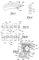
- Figure 9 is a sectional view of the sensor according to a third embodiment;
- Figure 10 is an exploded view of the components of the sensor shown in Figure 9;
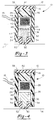
- Figure 11 is a plan view of the rotor of the sensor used in the third embodiment;
- Figure 12 is a sectional view of the rotor taken along the lines 12-12 in Figure 11;
- Figure 13 is a developed sectional view of the rotor and stator of the sensor taken with the rotor and stator in a first position;
- Figure 14 is a developed sectional view of the rotor and stator of the sensor taken with the rotor and stator in a second position;
- Figure 15 is a sectional view of the sensor according to a modification of the third embodiment;
- Figure 16 is a side view of the sensor of the fourth embodiment;
- Figure 17 is a sectional view of the sensor according to the fourth embodiment;
- Figure 18 is a sectional view of the sensor according to a modification of the fourth embodiment; and
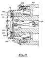
- Figure 19 is a view of the sensor mounted on a wheel spindle within a hubcap for measuring wheel speed.
- A preferably annular rotational speed sensor constructed according to the teachings of the present invention is indicated generally at 10 in Figure 1. The sensor is mounted in
stationary bore 12, and is driven by rotatingshaft 14. Electrical leads 16 come from an internal sensing coil. Figure 2 is an exploded view of the basic components employed in one exemplary embodiment ofspeed sensor 10. As shown in Figure 2, the components of the first embodiment telescope intosensor retainer 18 from the left. Edge 20 is rolled over to cooperate withlip 22 in retaining the sensor components withinretainer 18. The double-lipped design shown in Figure 2 is merely one example of suitable retaining means that could be used with the present embodiment. A variety of other retaining means can be used, including adhesives.Annular stator elements radial portion 30. Circumferentially spaced, radially disposedteeth 32 andslots 31 are formed on the inner faces ofstator elements corresponding teeth 34 andslots 33 formed inrotor 36 to provide the means for sensing rotational speed. The slots may be produced by forming teeth on the blank used to produce the stator elements and the rotor; or in the alternative, the slots may be formed by piercing openings in the respective blanks. Pierced openings offer a low magnetic permeability path to the flow of magnetic flux; whereas, the material between the pierced openings offers a high magnetic permeability path. The objective in either case is to provide a rotor and stator element which has respective radial portions which feature alternating circumferentially spaced regions offering first and second magnitudes of magnetic permeability. Axially poledannular magnet 38 provides magnetic flux forsensor 10. A sensing coil, shown encapsulated at 40, consists of a simple multi-turn winding oriented so that its axis is coincident with the linear axis of the assembled sensor. Other means for sensing variations in magnetic flux in the magnetic flux path may be used. (i.e., HALL sensors).Lead wires 16 extend from the two ends ofcoil 40 to connect the alternating voltage representing rotational speed signals to an external signal processing unit (not shown). - In this first exemplary embodiment,
rotor 36 is rotationally driven by a shaft. Bothrotor 36 andstator elements rotor teeth 34 is preferably slightly less than the length of thestator teeth 32. In addition,rotor teeth 34 are positioned relative to thestator teeth 32 in such a way that therotor teeth 34 lie within the length of thestator teeth 32. By this design, signal losses due to magnetic shunting and radial runout are reduced.Rotor 36 nests withincoil 40, and the rotor-coil combination nests coaxially withinmagnet 38. This assembly in turn is located coaxially with and sandwiched betweenstator elements - Figure 3 is a sectional view of the sensor shown in Figure 1 taken along lines 3-3 and looking in the direction of the arrows. In this view, the nesting relationship of
rotor 36,coil 40 andmagnet 38 is shown.Stator elements stator elements retainer 18 may be used to retain the sensor components therein. This particular cross section of thestator elements slots 31 are preferably filled withbacking material 44. Filling the slots results in a smooth continuous surface presented by the inner face of each stator element, so that if therotor 36 contacts statorelements stator elements -
Coil 40 is shown encapsulated bybobbin 46. Connections to the ends ofcoil 40 are made bylead wires 16, which exit throughstrain relief 48 onbobbin 46.Stator elements 24 andbacking material 44 are provided with an opening to allowstrain relief 48 to pass. -
Rotor 36 is slightly thinner than the space between thestator elements rotor 36 is less than the inner diameter ofcoil 40 to provide sufficient radial clearance to account for eccentricity and dimensional tolerances. - Several techniques can be used to fabricate
rotor 36 including sintering powdered iron.Rotor 36 may be a one-piece element, or may comprise two halves oriented with outwardly-facing teeth to operate in the same manner as the one-piece rotor. The rotor is preferably encapsulated in plastic or other suitable material (for example, backing material 44) such thatslots 33 are filled flush thus forming a unitary element regardless of one or two-piece design. -
Hub 50, shown on the inside diameter ofrotor 36, retainselastomeric ring 52.Ring 52 serves four functions. First, it provides a friction drive connection betweenshaft 14 andhub 50 ofrotor 36. Second, it provides vibration isolation of the rotor relative to its driving member. Third, the area of contact betweenstator elements ring 52 provides a running seal to keep contaminants out of the relatively moving parts ofsensor 10. Fourth, compression of the ring at the stator element sealing surface provides a centering force forrotor 36, tending to keep the rotor from contacting thestator elements - Friction drive of the rotor via
ring 52 is the preferred drive means for the rotational speed sensor; other drive means, however, including tangs or keys engaging slots on the rotating shaft, could also be used. - A toroidal
magnetic flux path 53 is thus established aroundcoil 40 and proceeds axially from one face ofmagnet 38 to one adjacent stator element, radially through the stator element, axially into and out ofrotor 36 into the other stator element, and finally radially through this second stator element and back intomagnet 38. Asrotor 36 rotates, the rotor andstator teeth coil 40 in accordance with known principles. The output voltage on leads 16 will be an alternating voltage with an amplitude proportional to the speed of rotation, and a frequency equal to the speed of rotation times the number of teeth in 360o. - The Figure 3 embodiment requires
retainer 18 to be non-magnetic to avoid shunting of magnetic flux. Furthermore, ifbore 12 is ferromagnetic, aspacer 42 must be included to avoid shunting by the bore. - Figure 4 shows the sensor cross section of Figure 3, but with
stator elements Stator elements Slots stator elements rotor 36 may be filled with nonmagnetic material as before to prevent damage due to rubbing. - Figure 5 shows a second embodiment of a rotational speed sensor. With reference to both Figure 5 and Figure 6,
rotor 136 is shown split into two halves, sandwichingmagnet 138.Magnet 138 has inner and outer diameters approximately equal to those of the rotor halves 135 and 137 so that the rotor-magnet assembly nests withincoil 140 and betweenstator elements Coil 140 may be adhesively or otherwise fastened tostator elements magnet 138 is appreciably greater than the combined air gaps shown at 154 and 156, the operating point on the demagnetization curve ofmagnet 138 will be high enough to provide an adequate change in flux to produce a sufficient voltage fromcoil 140.Magnet 138, is preferably as thin as is operationally practical. This embodiment has the advantages of reducing axial space requirements, decreasing the cost ofmagnet 138 and eliminating the shunting effect present when the sensor is placed in a ferrous bore. -
Rotor 136 is constructed to maintain a minimum rotor-stator clearance. In an exemplary construction, the two ferromagnetic rotor halves 135 and 137 are indexed and placed in a injection molding cavity withmagnet 138 between them. Rotor rims 158 and 160 are then molded aroundrotor halves magnet 138. - The molding cavity is constructed so that
air gaps magnet 138 betweenrotor halves magnet 138 across one air gap, radially through the adjacent stator element, then axially throughretainer 118, down radially through the other stator element, and back tomagnet 138. - Rotor rims 158 and 160 are shown abutting
stator element 124 with running clearance fromstator element 126. Rotor rims 158 and 160 may run in contact with either stator element or float between the stator elements, but are always in preventive contact withrotor 136. Although shown as rims, rotor rims 158 and 160 may be any suitable spacer means for maintaining rotor-stator spacing. A sine wave output fromcoil 140 is achieved with no anomalies when a clearance of a few thousandths of an inch is maintained between rotor andstator teeth - Since rotor rims 158 and 160 act as bearing surfaces running against
stator elements rims sensor 110 may be filled with grease or oil, with lubrication lands put in the rim area facing the stator elements. Depending upon wear characteristics, a single rotor rim may be used instead of two. - The
elastomeric ring 152, which forms the seal for this second embodiment, performs essentially the same functions aselastomeric ring 52 from the first embodiment, but is located differently on the second embodiment sensor. As shown in Figure 5,ring 152 extends along both the extension ofrim 160 andstator elements elastomeric ring 152 acts as a low-friction axial seal instead of as a radial seal. - All of the configurations discussed thus far are designed for speed sensing of a rotating shaft within a stationary bore. The present speed sensor may be modified to also satisfy requirements where the shaft is stationary and the bore rotates. Figure 7 shows a
sensor 210 mounted on astationary shaft 214 withrotor 236 being driven by arotating bore 212. The arrangement shown in Figure 7 functions in essentially the same manner as the arrangement of Figure 5, but with the radial positioning ofelastomeric ring 152,rotor 136, andcoil 140 reversed. Figure 7 showsshaft 214 being used to close the flux path. It must, therefore, have a composition capable of providing a magnetic flux path. As in the Figure 5 configuration, the stator elements may be fastened to the coil using adhesive. - As mentioned previously, friction drive of the rotor via the elastomeric ring is the preferred drive means for the rotational speed sensor. Friction drive makes assembly easy, and it eliminates alignment problems associated with locking the rotor to a driving element. Tang drive is possible, but requires extremely close tolerances to avoid backlash, which could give erroneous speed signals.
- Tang drive would be required, however, in certain circumstances where high drive torque might overcome the frictional force of a friction drive means. In such a circumstance, a combination of friction drive and tang drive is preferred. Figure 8 shows a partial sectional view through the center of a modified speed sensor mounted as in the Figure 5 embodiment, but incorporating a combined friction and tang drive.
Rotor rim 160 includestangs slots elastomeric ring 152.Slots ring 152 so as to maintain the integrity ofring 152.Drive member 182 hasslots tangs Slots elastomeric ring 152 and drivemember 182. When the torque requirement exceeds the frictional capabilities, however, tangs 163 and 165 are engaged viaslots - Figure 9 shows a third embodiment of the rotational speed sensor of the present invention. With reference to both Figure 9 and Figure 10,
rotor 410 is shown having several axially extendingpassageways 412 circumferentially spaced about the rotor. The passageways define openings on each opposing rotor surface.Magnets 414 are retained in the passageways by use of an adhesive or by mechanical interlock.Magnets 414 are aligned so as to offer common pole faces oriented toward opposing rotor surfaces. Therotor 410 is constructed from a low magnetic permeability material such as nylon. -
Stator elements material having slots 420.Slots 420 may be formed by piercing holes in the stator structure or by forming teeth which project from the stator structure itself. In either manner, the stator elements offer radial portions having alternating circumferentially spaced regions having first and second magnitudes of magnetic permeability. The magnets on the rotor provide a magnetic flux source and are arranged to produce a variable magnetic flux in a flux path formed around thecoil 426.Coil 426 provides a means for sensing variations in magnetic flux in said flux path. Theslots 420 are preferably filled with low magnetic permeability material to provide a relatively flat stator surface. - The radial length of the
magnets 414 is shorter than the radial length of thestator slots 420 to avoid magnetic shunting of the magnets. In addition, the circumferential width of themagnets 414 is preferably approximately the circumferential width of thestator slots 420 to permit the magnets to move into positions in which the magnetic flux path offers alternating high or low magnetic reluctance. - The plastic overmolds 422 and 424 are molded and secured to the stator elements by injection molding the overmolds with the
stator elements stator elements - The
stator elements wire coil 426.Wire coil 426 is preferably 1300 turns of No. 39 enameled wire wound and encapsulated inbobbin 428.Retainer 430 is constructed of high magnetic permeability material and serves to maintain structural connection of the stator elements as well as establish magnetic communication therebetween. Leadwires wire coil 426 and pass through theretainer 430 andstator element 418 viastrain relief 436. Theair gap 438 betweenrotor 410 andstator elements retainer 430 maintaining thestator elements bobbin 428. - In operation, the inner most radial portions of the
plastic overmold hub portion 448 ofrotor 410. If this occurs, very little wear will be experienced as therotor 410 is preferably constructed from nylon filled with long fiber aramid and the plastic overmolds 422 and 424 are preferably constructed from PPS having 10% glass and 5% Teflon. - A toroidal magnetic flux path is established around the
coil 426 proceeding from one pole face ofmagnets 414 passing through the teeth of thestator element 416 radially through the stator element, axially through theretainer 430 intostator element 418 radially therethrough into the respective stator teeth and finally to the opposing pole face ofmagnet 414. - As the rotor rotates, the
rotor magnets 414 move into and out of alignment withstator teeth 421 to alternately decrease and increase the magnetic flux flowing in the flux path. The change in magnitude of magnetic flux in the magnetic flux path generates a voltage incoil 426 in accordance with known principles. The relationship between themagnets 414 and thestator slots 420 is shown in Figure 13 and Figure 14. Figure 13 illustrates thestator elements teeth 421 in aligned positions with respect tomagnets 414 ofrotor 410. - Figure 14 illustrates the same components wherein the
rotor 410 has moved to a non-aligned position. In the preferred construction of this embodiment 100 magnets are used and each stator element has 100 slots. The output voltage across leads 432 and 434 shown in Figure 9 will be an alternating voltage with an amplitude proportional to the speed of rotation and a frequency equal to the speed of rotation times the number of teeth encountered in one revolution. - The
elastomeric ring 440 as shown in Figure 9 provides a compliant force frictionally engaging drivingshaft 442. In addition,ring 440 provides vibration isolation of the rotor relative toshaft 442. Finally, thering 440 includes twolip portions ring 440 is the preferred drive means for the sensor; other means however, including tangs or keys engaging slots on the rotating shaft could also be used. Asupplemental seal 446 may be used on either or both sides of the sensor to supplement the sealing action oflip portions - Figure 11 is a plan view of the
rotor 410 illustrating theaxially extending passageways 412 androtor hub 448. Figure 12 is a sectional view ofrotor 410 taken along the lines 12-12 in Figure 11 showingpassageway 412 having a first opening on a first radially extending surface ofrotor 410 and a second opening on a second radially extending surface and a portion of the passageway intermediate the openings having a smaller radial dimension so as to mechanically interlockmagnet 414 formed in the passageway. - The third embodiment as illustrated in Figure 9 features a
coil 426 radially spaced from therotor 410 whereby the coil and rotor provide a minimal axial package size. A variation of this embodiment, as shown in Figure 15, features acoil 500 axially spaced fromrotor 410 whereby thecoil 500 androtor 410 provide a minimal radial package size. The variation requires a modified stator and in all other respects is identical to the sensor of the third embodiment. As shown in Figure 15,stator elements material having slots 506. Teeth (not shown) are located intermediate the slots.Plastic overmolds stator elements Stator 504 has a flange portion which acts in conjunction with a flange portion formed integral to overmold 510 to define a cavity for receivingwire coil 500.Retainer 514 acts in conjunction with annularmagnetic flux conductor 516 to maintainstator coil 500 proceeding from one pole face ofmagnet 414 passing through the teeth of thestator element 502 radially through the stator element, axially through theretainer 514 into theannular conductor 516, radially through the annular conductor into thestator element 504, radially through the stator to the stator teeth and finally to the opposite pole face ofmagnet 414. All other components of the variation to the third embodiment are identical and retain identical numbers as previously described. - A fourth embodiment of the present invention is illustrated in side view in Figure 16 featuring a
rotor 510 havingslots 512 which defineteeth 514 therebetween. Therotor 510 engages a rotating shaft (not shown) as described in previous embodiments.Stator poles rotor 510 in a caliper-like fashion. Ferromagnetic teeth means 520 and 522 disposed on respective pole faces ofstator poles slots 512 andteeth 514 to define a variable reluctance path for magnetic flux supplied bymagnet 524. As described in previous embodiments, any technique for creating discontinuities in magnetic permeability of the interacting portions of the rotor and stator elements would be appropriate. In addition, previously described rotor and stator combinations, will perform in a manner similar to the rotor and stator combination described herein.Coil 526 contained inbobbin 528 encirclesmagnet 524 and produces a variable output voltage signal which corresponds in frequency to the change in magnetic flux passing through the flux path which begins with a first pole face ofmagnet 524, passes radially alongstator pole 516, axially throughteeth 520, a sector ofrotor 510, andteeth 522; radially throughstator pole 518 and back to a second opposing pole face ofmagnet 524. Asrotor 510 rotates, the rotor and stator teeth move into and out of juxtaposition to alternately decrease and increase the magnetic reluctance of the magnetic path. The change in reluctance increases and decreases the magnetic flux in the magnetic path. This change in flux generates a voltage incoil 526 in accordance with known principles. The output voltage of the sensor will be an alternating voltage with an amplitude proportional to the speed of rotation, and a frequency equal to the speed of rotation times the number of teeth encountered in one revolution. - Figure 18 illustrates an alternative of the fourth embodiment featuring
stator elements rotor 510 in a caliper-like fashion. The stator elements comprise two axially spaced members having first portions including ferromagnetic teeth means 520 and 522 which provide alternating circumferentially spaced regions of first and second magnetic permeability. - Second portions of the stator elements forming
stator poles rotor 510.Magnets ferromagnetic cylinder 534 provides magnetic communication between the second portions of the stator elements. - The magnetic flux path now begins at respective pole faces of the
magnets rotor 510, then radially throughstator 516, axially throughcylinder 534 and radially throughstator 518. Variations in magnetic flux passing through the flux path as a result of rotation ofrotor 510 causingteeth coil 526. This variation in voltage corresponds to the rate of rotation of the rotor times the number of teeth encountered in one rotation. The form of the invention illustrated in Figures 17 and 18 permits the stator and coil section of the sensor to be removed and serviced without requiring additional disassembly. - Figure 19 shows the
speed sensor 210 of Figure 7 applied to measure the speed of rotation of a non-driven wheel, as determined by measuring the rotational speed ofwheel hub 284.Elastomeric ring 252 contacts hubcap 212 along itsinside surface 286.Hubcap 212 is piloted onwheel hub 284 viaflange portion 288 to assure thathubcap 212 is concentric withwheel spindle 214. As thewheel spindle 214 andhub 284 turn,hubcap 212 drivesspeed sensor 210. -
Speed sensor 210 functions in essentially the same manner as the previously described sensors; however, the outer structural design ofspeed sensor 210 is modified to fit the particular exemplary plates molded intobacking layers 244 in a fashion similar to that described with respect to Figure 3.Channel 290 is formed in the backing material behind bothstator elements connector 292, and therefrom to external processing circuitry. Asensor hub 294 formed from the backing material of the internal stator slideably engagescounterbore 296 ofspindle 214. An O-ring 298 seals counterbore 296. -
Hubcap 212 seals the hub end and retains the bearing lubricant.Hubcap 212 is preferably an injection molding of a clear plastic to allow easy visual inspection of lubricant level.Channels 285 are provided inhubcap 212 to allow lubricant to flow from the spindle side ofsensor 210 to the hubcap side. - One skilled in the art will readily recognize that certain specific details shown in the foregoing specification and drawings are exemplary in nature and subject to modification without departing from the teachings of the disclosure. Various modifications of the invention discussed in the foregoing description will become apparent to those skilled in the art. All such variations that basically rely on the teachings through which the invention has advanced the art are properly considered within the spirit and scope of the invention.
Claims (38)
- A rotational speed sensor, comprising:
a stator including two coaxial, axially spaced elements;
said elements having first and second radially extending portions;
said first radial portions having alternating circumferentially spaced regions offering first and second magnitudes of magnetic permeability;
a rotor arranged for rotation about a rotational axis and having alternating circumferentially spaced regions offering first and second magnitudes of magnetic permeability;
said alternating circumferentially spaced regions of first and second magnitudes of magnetic permeability of said rotor and said stator elements being arranged in axially opposed relationship and in close proximity;
a magnet disposed between said stator elements;
said rotor, magnet and stator elements being arranged to form a magnetic flux path whereby a variation in a magnetic flux indicative of the rotational speed of said rotor relative to said stator is produced in said magnetic flux path upon rotation of said rotor; and
means for sensing variation in flux in said flux path. - A rotational speed sensor as claimed in claim 1, wherein said means for sensing variation in flux is a coil.
- A rotational speed sensor as claimed in claim 1, wherein said magnet is radially spaced with respect to said rotor.
- A rotational speed sensor as claimed in claim 3, further comprising a nonferromagnetic spacer means arranged to prevent shunting of a magnetic flux path away from said magnet.
- A rotational speed sensor as claimed in claim 1 wherein said rotor comprises two coaxial halves, said magnet is disposed between said rotor halves and each said stator element is connected by a retainer means which provides a flux path therebetween.
- A rotational speed sensor as claimed in claim 2 wherein said rotor nests within said coil whereby said rotor may be rotated by a centrally located driving element while the coil and stator are maintained nonrotating in a radially outward region.
- A rotational speed sensor as claimed in claim 2 wherein said coil nests within said rotor whereby said rotor may be rotated by an outer annular driving element while the coil and stator are maintained nonrotating in a central region.
- A rotational speed sensor as claimed in claim 1 wherein said alternating circumferentially spaced regions offering first and second magnitudes of magnetic permeability include ferromagnetic teeth means disposed on said first radial portions of said stator elements and said first and second axially spaced radially extending surfaces of said rotor.
- A rotational speed sensor as claimed in claim 1 wherein said alternating circumferentially spaced regions offering first and second magnitudes of magnetic permeability comprise openings formed in said stator and said rotor.
- A rotational speed sensor as claimed in claim 8 further comprising a nonferromagnetic component at least filling the spaces between the teeth means on the opposing surfaces of said stator and rotor but not covering the teeth means, whereby magnetic flux traversing the stator and rotor teeth means during operation of the sensor is not altered by the nonferromagnetic component and said opposing radial surfaces of said rotor and stator are relatively flat in profile.
- A rotational speed sensor as claimed in claim 2 comprising retainer means arranged to retain said stator, coil, rotor and magnet in a unitized assembly.
- A rotational speed sensor as claimed in claim 1, further comprising resilient seal means associated with said sensor and arranged to prevent passage of contaminants from at least one direction.
- A rotational speed sensor as claimed in claim 1 wherein said sensor includes friction drive means.
- A rotational speed sensor as claimed in claim 12, wherein said friction drive means comprises a resilient element engaging a driving member.
- A rotational speed sensor as claimed in claim 13 wherein said resilient element has an aperture and said aperture is arranged to engage a tang drive means disposed on said drive member.
- A rotational speed sensor as claimed in claim 1 further comprising;
means for providing a friction drive for said rotor; and
seal means for preventing entry of contaminants into said sensor. - A rotational speed sensor as claimed in claim 16 wherein both said friction drive means and said seal means comprise a unitary resilient seal and drive element.
- A rotational speed sensor as claimed in claim 17, wherein said rotor is annular and includes diametrical inner and outer surfaces, and wherein said seal and drive element extends along one said surface of said rotor and is in sealing association with said stator.
- A rotational speed sensor as claimed in claim 1, including spacer means arranged to maintain axial spacing between said rotor and stator teeth means.
- An electrical rotational speed sensor including a nonrotatable spindle terminating at an end area; a rotatable hub mounted on the spindle; a hub cap disposed adjacent the spindle end area and connected to the hub for rotation therewith; a rotor element connected to said hub cap for rotation therewith, a stator element connected to said spindle; means for generating an electrical signal indicative of the speed of rotation of said rotor relative to said stator; said stator comprising two coaxial, axially spaced elements, each said stator element having axially opposed inner and outer radially extending surfaces, each inner radially extending surface having circumferentially spaced ferromagnetic teeth means disposed thereon; said rotor having first and second axially spaced radially extending surfaces, including circumferentially spaced ferromagnetic teeth means disposed on said first and second surfaces; said means for generating said electrical signal comprising a wire coil disposed between and coaxial with said stator elements and a magnet disposed between and coaxial with said stator elements; said rotor element, coil and magnet being coaxially nested between said stator elements, with the teeth means of each of said stator elements being in close axially spaced proximity to the teeth means of the rotor element and with said coil nonrotatably connected to said spindle, said rotor and stator teeth, coil and magnet arranged to provide a magnetic flux path; whereby upon rotation of said hub relative to said spindle, said electrical signal is generated indicative of the speed of rotation of the hub relative to the spindle due to the periodic variance of magnetic flux across said opposed teeth.
- A rotational speed sensor comprising;
a stator including two coaxial, axially spaced elements, each said stator having axially opposed first and second radially extending surfaces, each first radially extending surface having circumferentially spaced ferromagnetic teeth means disposed thereon,
a coil of wire disposed between said stator elements and coaxial therewith;
a rotor having axially spaced halves;
said rotor halves each having first and second axially spaced radially extending surfaces including circumferentially spaced ferromagnetic teeth means disposed on said surfaces;
a magnet disposed between said rotor halves;
a retainer means providing a flux path between each of said stator elements;
said rotor halves, coil and magnet being coaxially nested between said stator elements with said teeth means of each of said stator elements being arranged in axially opposed relationship and in close proximity to the teeth means of a respective adjacent rotor surface; and
said magnet, retainer, rotor halves and stator elements arranged to form a magnetic flux path about said coil whereby an electric current indicative of the speed of said rotor relative to said stator is induced in said coil upon rotation of said rotor due to periodic variation of said flux path at said teeth means. - A rotational speed sensor as claimed in claim 20, further comprising nonferromagnetic spacer means arranged to prevent shunting of magnetic flux path away from said magnet.
- A rotational speed sensor as claimed in claim 21 wherein said rotor nests within said coil whereby said rotor may be rotated by a centrally located driving element while the coil and stator are maintained nonrotating in a radially outward region.
- A rotational speed sensor as claimed in claim 21 wherein said coil nests within said rotor whereby said rotor may be rotated by an outer annular driving element while the coil and stator are maintained nonrotating in a central region.
- A rotational speed sensor as claimed in claim 21 wherein said alternating circumferentially spaced regions offering first and second magnitudes of magnetic permeability include ferromagnetic teeth means disposed on said first radial portions of said stator elements and said first and second axially spaced radially extending surfaces of said rotor.
- A rotational speed sensor as claimed in claim 21 wherein said alternating circumferentially spaced regions offering first and second magnitudes of magnetic permeability include openings formed in said stator and said rotor.
- A rotational speed sensor as claimed in claim 21 further comprising a nonferromagnetic component at least filling the spaces between the teeth means on the opposing surfaces of the stator and rotor (They could be covered if someone could figure out how to control the thickness of the overmold so that it would not be too thick - .005+.) whereby magnetic flux traversing the stator and rotor teeth means during operation of the sensor is not altered by the nonferromagnetic component and said opposing radial surfaces of said rotor and stator are relatively flat in profile.
- A rotational speed sensor as claimed in claim 21, further comprising resilient seal means associated with said sensor and arranged to prevent passage of contaminants from at least one direction.
- A rotational speed sensor as claimed in claim 21 wherein said sensor includes friction drive means.
- A rotational speed sensor as claimed in claim 21, wherein said friction drive means comprises a resilient element engaging a driving member.
- A rotational speed sensor as claimed in claim 21 wherein said resilient element has an aperture and said aperture is arranged to engage a tang drive means disposed on said drive member.
- A rotational speed sensor as claimed in claim 21 further comprising;
means for providing a friction drive for said rotor; and
seal means for preventing entry of contaminants into said sensor. - A rotational speed sensor as claimed in claim 21 wherein both said friction drive means and said seal means comprise a unitary resilient seal and drive element.
- A rotational speed sensor as claimed in claim 21, wherein said rotor is annular and includes diametrical inner and outer edge surfaces, and wherein said seal and drive elements extends along one said edge surface of said rotor and is in sealing association with said stator.
- A rotational speed sensor as claimed in claim 21 including spacer means arranged to maintain axial spacing between said rotor and stator teeth means.
- An electrical rotational speed sensor including a nonrotatable spindle terminating at an end area; a rotatable hub mounted on the spindle; a hub cap disposed adjacent the spindle end area and connected to the hub for rotation therewith; a rotor element connected to said hub cap for rotation therewith; a stator element connected to said spindle; means for generating an electrical signal indicative of the speed of rotation of said rotor relative to said stator; said stator comprising two coaxial, axially spaced elements, each said stator having axially opposed first and second radially extending surfaces, each first radially extending surface having circumferentially spaced ferromagnetic teeth means disposed thereon, a rotor having axially spaced halves;
said rotor halves each having first and second axially spaced radially extending surfaces including circumferentially spaced ferromagnetic teeth means disposed on said surfaces;
a magnetic disposed between said rotor halves;
a retainer means providing a flux path between each of said stator elements;
said rotor halves, coil and magnet being coaxially nested between said stator elements;
said means for generating said electrical signal comprising a wire coil disposed between and coaxial with said stator elements;
said rotor halves, magnet and coil being coaxially nested between said stator elements with the teeth means of each of said stator elements being in close axially spaced proximity to the teeth means of the rotor element and with said coil nonrotatable connected to said spindle; and
said magnet, retainer, rotor halves, and teeth means arranged to provide a magnetic flux path whereby upon rotation of said hub relative to said spindle, said electrical signal is generated indicative of the speed of rotation of the hub relative to the spindle due to the periodic variance of magnetic flux across opposed teeth. - A rotational speed sensor as claimed in claim 13 wherein said resilient element has an aperture and said aperture is arranged to engage a tang drive means disposed on said drive member.
- A rotational speed sensor comprising;
a rotor arranged for rotation about a rotational axis and having alternating circumferentially spaced regions offering first and second magnitudes of magnetic permeability;
a stator including two axially spaced elements;
said stator elements having first and second portions;
said first portions having alternating circumferentially spaced regions offering first and second magnitudes of magnetic permeability;
said alternating circumferentially spaced regions of first and second magnitude of magnetic permeability of said rotor and said stator elements being arranged in axially opposed relationship and in close proximity;
said second portions of said stator elements being axially spaced and radially extending from said first portions;
a magnet disposed between each of said first and second portions of said stator elements;
means for magnetic communication between said second portions; and
a coil disposed about said means for magnetic communications wherein an electrical signal is generated indicative of the speed of rotation of said rotor relative to said stator due to the periodic variance of magnetic flux across the alternating circumferentially spaced regions of said rotor and said stator.
Applications Claiming Priority (3)
| Application Number | Priority Date | Filing Date | Title |
|---|---|---|---|
| US463736 | 1990-01-12 | ||
| US07/463,736 US5111098A (en) | 1988-08-24 | 1990-01-12 | Unitary rotational speed sensor |
| EP90125046A EP0437796B1 (en) | 1990-01-12 | 1990-12-20 | Unitary rotational speed sensor |
Related Parent Applications (1)
| Application Number | Title | Priority Date | Filing Date |
|---|---|---|---|
| EP90125046.4 Division | 1990-12-20 |
Publications (2)
| Publication Number | Publication Date |
|---|---|
| EP0632272A2 true EP0632272A2 (en) | 1995-01-04 |
| EP0632272A3 EP0632272A3 (en) | 1995-04-12 |
Family
ID=23841162
Family Applications (2)
| Application Number | Title | Priority Date | Filing Date |
|---|---|---|---|
| EP94116159A Withdrawn EP0632272A3 (en) | 1990-01-12 | 1990-12-20 | Unitary rotational speed sensor. |
| EP90125046A Expired - Lifetime EP0437796B1 (en) | 1990-01-12 | 1990-12-20 | Unitary rotational speed sensor |
Family Applications After (1)
| Application Number | Title | Priority Date | Filing Date |
|---|---|---|---|
| EP90125046A Expired - Lifetime EP0437796B1 (en) | 1990-01-12 | 1990-12-20 | Unitary rotational speed sensor |
Country Status (7)
| Country | Link |
|---|---|
| US (1) | US5111098A (en) |
| EP (2) | EP0632272A3 (en) |
| JP (1) | JPH04212066A (en) |
| AU (1) | AU653710B2 (en) |
| BR (1) | BR9100056A (en) |
| DE (2) | DE69018958T2 (en) |
| ES (1) | ES2023628T3 (en) |
Cited By (5)
| Publication number | Priority date | Publication date | Assignee | Title |
|---|---|---|---|---|
| EP0747709A1 (en) * | 1995-06-06 | 1996-12-11 | Ssi Technologies, Inc. | Apparatus for sensing the speed of a rotating element |
| DE19533385A1 (en) * | 1995-09-09 | 1997-03-13 | Kostal Leopold Gmbh & Co Kg | Sensor unit for determining rpm of spur gear type component located in housing |
| WO1997048984A1 (en) * | 1996-06-17 | 1997-12-24 | Philips Electronics N.V. | Electric motor with tachometer signal generator |
| DE19732347A1 (en) * | 1997-07-28 | 1999-02-04 | Mannesmann Vdo Ag | Device to determine relative speed between rotating and stationary part |
| CN110065098A (en) * | 2019-06-03 | 2019-07-30 | 江苏万宝瑞达高新技术有限公司 | A kind of scraper device preventing holiday or disconnected paper |
Families Citing this family (37)
| Publication number | Priority date | Publication date | Assignee | Title |
|---|---|---|---|---|
| GB9116918D0 (en) * | 1991-08-06 | 1991-09-18 | Lucas Ind Plc | Fuel pumping apparatus |
| US5281911A (en) * | 1991-11-08 | 1994-01-25 | Eaton Corporation | Vehicle wheel speed sensor employing a locating plate |
| US5200697B1 (en) * | 1991-11-27 | 1996-06-18 | Ntn Toyo Bearing Co Ltd | Hub and bearing assembly with integrated rotation sensor including a tone ring and annular transducer |
| DE4243624A1 (en) * | 1991-12-27 | 1993-07-01 | Ntn Toyo Bearing Co Ltd | Revolution rate detector, esp. for vehicle bearings, - contains pulse transducer ring with sensor contg. coil, high frequency voltage source and detector |
| US5296805A (en) * | 1992-08-17 | 1994-03-22 | General Motors Corporation | Serviceable wheel speed sensor with magnet assisted retention |
| JP2605140Y2 (en) * | 1993-01-22 | 2000-06-26 | 日産自動車株式会社 | Rotation speed sensor |
| US5291130A (en) * | 1993-01-25 | 1994-03-01 | Eaton Corporation | Vehicle wheel speed sensor employing an adaptable rotor cap |
| US5504424A (en) * | 1993-05-28 | 1996-04-02 | Durakool, Inc. | Variable reluctance sensor utilizing a magnetic bobbin |
| FR2710985B1 (en) * | 1993-10-06 | 1995-11-24 | Skf France | Encoder element for bearings provided with an information sensor and bearing assembly comprising such an encoder element. |
| US5705873A (en) * | 1993-12-22 | 1998-01-06 | Canon Denshi Kabushiki Kaisha | Light-quantity control device |
| US5574361A (en) * | 1994-12-27 | 1996-11-12 | Ssi Technologies, Inc. | Switched reluctance angular velocity sensor |
| US5491407A (en) * | 1995-02-03 | 1996-02-13 | Kearney-National, Inc. | Wheel bearing speed sensor |
| JPH08278318A (en) * | 1995-03-31 | 1996-10-22 | Ntn Corp | Rotary sensor for wheel support bearing |
| AU7237996A (en) * | 1995-09-05 | 1997-03-27 | Cts Corporation | Rotary position sensor with insert molded coil winding |
| JP3301303B2 (en) * | 1995-10-13 | 2002-07-15 | トヨタ自動車株式会社 | Electric motor |
| US6348751B1 (en) | 1997-12-12 | 2002-02-19 | New Generation Motors Corporation | Electric motor with active hysteresis-based control of winding currents and/or having an efficient stator winding arrangement and/or adjustable air gap |
| US6100615A (en) * | 1998-05-11 | 2000-08-08 | Birkestrand; Orville J. | Modular motorized electric wheel hub assembly for bicycles and the like |
| US6253614B1 (en) * | 1998-07-15 | 2001-07-03 | Ssi Technologies, Inc. | Speed sensor having a UV-cured glue seal and a method of applying the same |
| CA2345040A1 (en) * | 1999-07-23 | 2001-02-01 | Advanced Rotary Systems, Llc | Electric drive (options) |
| JP3651575B2 (en) * | 1999-09-06 | 2005-05-25 | スズキ株式会社 | Vehicle propulsion device |
| SI20497B (en) * | 2000-01-14 | 2008-08-31 | Harmonic Drive Systems | Synchronous hybrid electric machine with toroid coil |
| US6707188B2 (en) * | 2000-05-08 | 2004-03-16 | Asmo Co., Ltd. | Motor having rotational sensor |
| US6400050B1 (en) | 2000-07-14 | 2002-06-04 | Robert Bosch Corporation | Motor having rotating movement detection capability |
| US6952068B2 (en) * | 2000-12-18 | 2005-10-04 | Otis Elevator Company | Fabricated components of transverse flux electric motors |
| US20030137210A1 (en) * | 2001-08-17 | 2003-07-24 | Southall Otway Archer | Integrated commutator and slip-ring with sense magnet |
| US6984916B2 (en) * | 2001-08-17 | 2006-01-10 | Energy Conversion Systems Holdings, Llc | Integrated commutator with sense magnet |
| JP4044880B2 (en) * | 2003-08-05 | 2008-02-06 | 株式会社日立製作所 | Non-contact angle measuring device |
| US20070176593A1 (en) * | 2006-01-31 | 2007-08-02 | Paul Fathauer | Transmission sensor with overmolding and method of manufacturing the same |
| DE102006020602A1 (en) * | 2006-05-02 | 2007-11-08 | Rolls-Royce Deutschland Ltd & Co Kg | Inductive sensor for measuring e.g. rotation speed of shaft, has permanent magnet for generating magnetic field, where closed magnetic path of magnetic flow line comprises air gap, in which rotating component is engaged |
| GB2442622B (en) * | 2006-08-04 | 2009-06-24 | Clean Current Power Systems Inc | Rotor and stator segments for generator and motor |
| EP2247461A1 (en) * | 2007-12-28 | 2010-11-10 | Clean Current Power Systems Incorporated | Hybrid electric power system with distributed segmented generator/motor |
| US8742750B2 (en) * | 2008-06-13 | 2014-06-03 | Eaton Corporation | Speed sensor pick-up for fluid device |
| US8013696B2 (en) * | 2008-10-14 | 2011-09-06 | Nexteer (Beijing) Technology Co., Ltd. | Magnetic apparatus and method of manufacturing the magnetic apparatus |
| FR3031589B1 (en) * | 2015-01-13 | 2018-11-16 | Hutchinson | INDUCTIVE DISPLACEMENT SENSORS |
| US9797268B2 (en) * | 2015-03-27 | 2017-10-24 | United Technologies Corporation | Oil scoop with integrated sensor |
| US10829201B2 (en) * | 2019-03-20 | 2020-11-10 | Pratt & Whitney Canada Corp. | Blade angle position feedback system with extended markers |
| CN111537761B (en) * | 2020-05-29 | 2023-06-30 | 西安航空制动科技有限公司 | Electromagnetic type double-toothed ring machine wheel speed sensor |
Citations (15)
| Publication number | Priority date | Publication date | Assignee | Title |
|---|---|---|---|---|
| GB600980A (en) * | 1945-10-08 | 1948-04-23 | British Thomson Houston Co Ltd | Improvements relating to the stroboscopic observation of shafts and like rotating members |
| US3564313A (en) * | 1969-08-08 | 1971-02-16 | Trans Sonics Inc | Self-compensating tachometer generator |
| US3571640A (en) * | 1969-04-25 | 1971-03-23 | Kelsey Hayes Co | Flux reversing sensor |
| DE1773149A1 (en) * | 1968-04-06 | 1971-09-02 | Siemens Ag | Device for indicating the direction of rotation of drives |
| US3604966A (en) * | 1969-09-22 | 1971-09-14 | Kelsey Hayes Co | Rotational speed sensor |
| US3649859A (en) * | 1970-06-15 | 1972-03-14 | Kelsey Hayes Co | Sensor with constant airgap |
| US3683219A (en) * | 1969-12-10 | 1972-08-08 | Daimler Benz Ag | Measurement-sensing device for determining a rotational speed or rotational speed change, preferably of vehicle wheels |
| US3769533A (en) * | 1972-05-22 | 1973-10-30 | Bendix Corp | Adaptive braking wheel speed sensor |
| GB1381501A (en) * | 1971-01-15 | 1975-01-22 | Girling Ltd | Electrical angular speed sensor |
| US3927339A (en) * | 1971-12-07 | 1975-12-16 | Daimler Benz Ag | Frequency transmitters for producing control signals controlling the brake force in motor vehicle wheels |
| US4110647A (en) * | 1977-01-13 | 1978-08-29 | The Bendix Corporation | Wheel speed sensor |
| GB2043256A (en) * | 1979-02-22 | 1980-10-01 | Bosch Gmbh Robert | Rotation sensor |
| EP0159069A2 (en) * | 1984-04-11 | 1985-10-23 | Mavilor Systèmes S.A. | Electronically commutated electric motor without collector |
| EP0213732A1 (en) * | 1985-07-26 | 1987-03-11 | Honda Giken Kogyo Kabushiki Kaisha | Magnetic ring for detecting the rotation of an object |
| EP0357870A2 (en) * | 1988-08-24 | 1990-03-14 | Rockwell International Corporation | Unitary rotational speed sensor |
Family Cites Families (21)
| Publication number | Priority date | Publication date | Assignee | Title |
|---|---|---|---|---|
| US2567422A (en) * | 1948-01-08 | 1951-09-11 | Tennessee Coal Iron And Railro | Sheet counter |
| FR1234263A (en) * | 1959-05-12 | 1960-10-17 | Electronique & Automatisme Sa | High frequency alternator |
| AT216089B (en) * | 1959-09-07 | 1961-07-10 | Elektro Motoren Ag | AC machine |
| US3230407A (en) * | 1962-08-01 | 1966-01-18 | Anelex Corp | Electromagnetic transducers |
| US3480812A (en) * | 1967-08-17 | 1969-11-25 | Gen Electric | Signal generating device for use in conjunction with a dynamoelectric machine and the like |
| US3515920A (en) * | 1968-07-18 | 1970-06-02 | Kelsey Hayes Co | Permanent magnet inductor generator for vehicle wheel speed sensor |
| US3551712A (en) * | 1968-07-25 | 1970-12-29 | Kelsey Hayes Co | Sensor with flexible coupling |
| US3489935A (en) * | 1968-08-08 | 1970-01-13 | Kelsey Hayes Co | Vehicle wheel inductor generator with one air gap filled with low reluctance material |
| DE1950647A1 (en) * | 1969-10-08 | 1971-04-22 | Bosch Gmbh Robert | Device for detecting the slip of vehicle wheels |
| PL71917B1 (en) * | 1969-11-10 | 1974-06-29 | Lucas Industries Ltd | |
| US3646376A (en) * | 1970-05-01 | 1972-02-29 | Gen Electric | High-frequency tachometer generator |
| US3626226A (en) * | 1970-06-01 | 1971-12-07 | Bendix Corp | Wheel speed sensor for an adaptive braking system |
| DE2053262B2 (en) * | 1970-10-30 | 1972-09-21 | Robert Bosch Gmbh, 7000 Stuttgart | AC voltage generator for speed measurement, in particular for an anti-lock device of a vehicle brake system |
| CH539996A (en) * | 1971-08-10 | 1973-07-31 | Stoll & Co H | Pulse generator on an electronic control device of a machine, in particular on a program control device of a knitting machine |
| US3772549A (en) * | 1972-05-02 | 1973-11-13 | Rockwell International Corp | Wheel speed sensor |
| US3812391A (en) * | 1972-06-16 | 1974-05-21 | Rockwell International Corp | Wheel speed sensor |
| US3854556A (en) * | 1973-12-27 | 1974-12-17 | Eaton Corp | Anti-skid system having improved sensor |
| US4061938A (en) * | 1975-06-20 | 1977-12-06 | Matsushita Electric Industrial Co., Ltd. | Device for generating electrical pulses in response to shaft rotation |
| US4171495A (en) * | 1978-03-20 | 1979-10-16 | Eaton Corporation | Wheel speed sensor |
| JPS6039336A (en) * | 1983-08-12 | 1985-03-01 | Nippon Denso Co Ltd | Cooling structure of flat type rotary electric machine |
| US4639626A (en) * | 1985-04-26 | 1987-01-27 | Magnetics Research International Corporation | Permanent magnet variable reluctance generator |
-
1990
- 1990-01-12 US US07/463,736 patent/US5111098A/en not_active Expired - Fee Related
- 1990-12-13 AU AU68012/90A patent/AU653710B2/en not_active Ceased
- 1990-12-20 ES ES90125046T patent/ES2023628T3/en not_active Expired - Lifetime
- 1990-12-20 DE DE69018958T patent/DE69018958T2/en not_active Expired - Fee Related
- 1990-12-20 EP EP94116159A patent/EP0632272A3/en not_active Withdrawn
- 1990-12-20 EP EP90125046A patent/EP0437796B1/en not_active Expired - Lifetime
- 1990-12-20 DE DE199090125046T patent/DE437796T1/en active Pending
-
1991
- 1991-01-09 BR BR919100056A patent/BR9100056A/en not_active IP Right Cessation
- 1991-01-10 JP JP3001605A patent/JPH04212066A/en active Pending
Patent Citations (15)
| Publication number | Priority date | Publication date | Assignee | Title |
|---|---|---|---|---|
| GB600980A (en) * | 1945-10-08 | 1948-04-23 | British Thomson Houston Co Ltd | Improvements relating to the stroboscopic observation of shafts and like rotating members |
| DE1773149A1 (en) * | 1968-04-06 | 1971-09-02 | Siemens Ag | Device for indicating the direction of rotation of drives |
| US3571640A (en) * | 1969-04-25 | 1971-03-23 | Kelsey Hayes Co | Flux reversing sensor |
| US3564313A (en) * | 1969-08-08 | 1971-02-16 | Trans Sonics Inc | Self-compensating tachometer generator |
| US3604966A (en) * | 1969-09-22 | 1971-09-14 | Kelsey Hayes Co | Rotational speed sensor |
| US3683219A (en) * | 1969-12-10 | 1972-08-08 | Daimler Benz Ag | Measurement-sensing device for determining a rotational speed or rotational speed change, preferably of vehicle wheels |
| US3649859A (en) * | 1970-06-15 | 1972-03-14 | Kelsey Hayes Co | Sensor with constant airgap |
| GB1381501A (en) * | 1971-01-15 | 1975-01-22 | Girling Ltd | Electrical angular speed sensor |
| US3927339A (en) * | 1971-12-07 | 1975-12-16 | Daimler Benz Ag | Frequency transmitters for producing control signals controlling the brake force in motor vehicle wheels |
| US3769533A (en) * | 1972-05-22 | 1973-10-30 | Bendix Corp | Adaptive braking wheel speed sensor |
| US4110647A (en) * | 1977-01-13 | 1978-08-29 | The Bendix Corporation | Wheel speed sensor |
| GB2043256A (en) * | 1979-02-22 | 1980-10-01 | Bosch Gmbh Robert | Rotation sensor |
| EP0159069A2 (en) * | 1984-04-11 | 1985-10-23 | Mavilor Systèmes S.A. | Electronically commutated electric motor without collector |
| EP0213732A1 (en) * | 1985-07-26 | 1987-03-11 | Honda Giken Kogyo Kabushiki Kaisha | Magnetic ring for detecting the rotation of an object |
| EP0357870A2 (en) * | 1988-08-24 | 1990-03-14 | Rockwell International Corporation | Unitary rotational speed sensor |
Non-Patent Citations (1)
| Title |
|---|
| RESEARCH DISCLOSURE, no. 296, December 1988, page 961, abstact no. 29634, New York US; PAWLAK ET AL: "Variable reluctance sensor" * |
Cited By (7)
| Publication number | Priority date | Publication date | Assignee | Title |
|---|---|---|---|---|
| EP0747709A1 (en) * | 1995-06-06 | 1996-12-11 | Ssi Technologies, Inc. | Apparatus for sensing the speed of a rotating element |
| US5825176A (en) * | 1995-06-06 | 1998-10-20 | Ssi Technologies, Inc. | Sensor mounted adjacent an outer member for sensing the rotational speed of a inner member |
| DE19533385A1 (en) * | 1995-09-09 | 1997-03-13 | Kostal Leopold Gmbh & Co Kg | Sensor unit for determining rpm of spur gear type component located in housing |
| WO1997048984A1 (en) * | 1996-06-17 | 1997-12-24 | Philips Electronics N.V. | Electric motor with tachometer signal generator |
| DE19732347A1 (en) * | 1997-07-28 | 1999-02-04 | Mannesmann Vdo Ag | Device to determine relative speed between rotating and stationary part |
| CN110065098A (en) * | 2019-06-03 | 2019-07-30 | 江苏万宝瑞达高新技术有限公司 | A kind of scraper device preventing holiday or disconnected paper |
| CN110065098B (en) * | 2019-06-03 | 2024-03-19 | 江苏万宝瑞达高新技术有限公司 | Scraper device for preventing missing coating or paper breakage |
Also Published As
| Publication number | Publication date |
|---|---|
| AU6801290A (en) | 1991-07-18 |
| DE437796T1 (en) | 1991-11-07 |
| DE69018958D1 (en) | 1995-06-01 |
| JPH04212066A (en) | 1992-08-03 |
| US5111098A (en) | 1992-05-05 |
| EP0437796A3 (en) | 1991-11-21 |
| EP0437796A2 (en) | 1991-07-24 |
| EP0632272A3 (en) | 1995-04-12 |
| ES2023628A4 (en) | 1992-02-01 |
| AU653710B2 (en) | 1994-10-13 |
| DE69018958T2 (en) | 1995-09-21 |
| BR9100056A (en) | 1991-10-22 |
| EP0437796B1 (en) | 1995-04-26 |
| ES2023628T3 (en) | 1995-08-01 |
Similar Documents
| Publication | Publication Date | Title |
|---|---|---|
| US5111098A (en) | Unitary rotational speed sensor | |
| EP0942186B1 (en) | Rolling bearing unit with rotating speed sensor | |
| CA1333964C (en) | Unitary rotational speed sensor | |
| EP2233901A1 (en) | Torque detecting apparatus and manufacturing method thereof | |
| US5223760A (en) | Wheel speed sensor for drive axle | |
| US5583431A (en) | Hub unit with rotation speed sensor | |
| US5508608A (en) | Magnetic flux device for measuring rotary motions and for generating an electric alternating signal representative of the rotary motions | |
| JPH0543749U (en) | Rotor of rotating magnetic field type motor | |
| US20150300412A1 (en) | Resolver bearing | |
| US20050174106A1 (en) | Rolling bearing | |
| KR20050033002A (en) | Sealing device and rotation detector | |
| US5111138A (en) | Speed sensor having a closed magnetic flux path for sensing speed from an axial face of a rotating member | |
| US5744720A (en) | Rolling bearing unit with rotating speed detector | |
| EP0721106B1 (en) | Improved switched reluctance speed sensor | |
| US6003375A (en) | Hub unit with rotation speed sensor | |
| JP2019022393A (en) | motor | |
| JP3653885B2 (en) | Magnetizer for encoder for rotational speed detector | |
| EP0442121B1 (en) | Gearing system comprising a rotational speed sensor | |
| KR20000070595A (en) | Metering device for contactless determination of a rotation | |
| EP4130681A1 (en) | Absolute magnetic encoder and setting method | |
| JP6651269B2 (en) | Rotating electric machine | |
| JP3948053B2 (en) | Rolling bearing unit with rotational speed detector | |
| JPH10253647A (en) | Rolling bearing unit with rotational-speed detecting device | |
| JPH08178939A (en) | Rolling bearing unit with rotating speed detecting device | |
| JPH1062440A (en) | Rolling bearing unit with rotational speed detector |
Legal Events
| Date | Code | Title | Description |
|---|---|---|---|
| PUAI | Public reference made under article 153(3) epc to a published international application that has entered the european phase |
Free format text: ORIGINAL CODE: 0009012 |
|
| AC | Divisional application: reference to earlier application |
Ref document number: 437796 Country of ref document: EP |
|
| AK | Designated contracting states |
Kind code of ref document: A2 Designated state(s): DE ES FR GB IT |
|
| PUAL | Search report despatched |
Free format text: ORIGINAL CODE: 0009013 |
|
| AK | Designated contracting states |
Kind code of ref document: A3 Designated state(s): DE ES FR GB IT |
|
| RIN1 | Information on inventor provided before grant (corrected) |
Inventor name: KRAMER, DENNIS A. Inventor name: PLATZER, GEORGE E. Inventor name: PECK, DAVID E. Inventor name: KRUSEL, WILLIAM D. |
|
| RIN1 | Information on inventor provided before grant (corrected) |
Inventor name: KRAMER, DENNIS A. Inventor name: PLATZER, GEORGE E. Inventor name: PECK, DAVID E. Inventor name: KRUSEL, WILLIAM D. |
|
| 17P | Request for examination filed |
Effective date: 19950927 |
|
| 17Q | First examination report despatched |
Effective date: 19970930 |
|
| STAA | Information on the status of an ep patent application or granted ep patent |
Free format text: STATUS: THE APPLICATION IS DEEMED TO BE WITHDRAWN |
|
| 18D | Application deemed to be withdrawn |
Effective date: 19980211 |