EP0630170A2 - Electrical connection for window - Google Patents
Electrical connection for window Download PDFInfo
- Publication number
- EP0630170A2 EP0630170A2 EP94401279A EP94401279A EP0630170A2 EP 0630170 A2 EP0630170 A2 EP 0630170A2 EP 94401279 A EP94401279 A EP 94401279A EP 94401279 A EP94401279 A EP 94401279A EP 0630170 A2 EP0630170 A2 EP 0630170A2
- Authority
- EP
- European Patent Office
- Prior art keywords
- glazing
- cable
- glazing according
- sheath
- conductive
- Prior art date
- Legal status (The legal status is an assumption and is not a legal conclusion. Google has not performed a legal analysis and makes no representation as to the accuracy of the status listed.)
- Granted
Links
Images


Classifications
-
- H—ELECTRICITY
- H05—ELECTRIC TECHNIQUES NOT OTHERWISE PROVIDED FOR
- H05B—ELECTRIC HEATING; ELECTRIC LIGHT SOURCES NOT OTHERWISE PROVIDED FOR; CIRCUIT ARRANGEMENTS FOR ELECTRIC LIGHT SOURCES, IN GENERAL
- H05B3/00—Ohmic-resistance heating
- H05B3/84—Heating arrangements specially adapted for transparent or reflecting areas, e.g. for demisting or de-icing windows, mirrors or vehicle windshields
-
- H—ELECTRICITY
- H05—ELECTRIC TECHNIQUES NOT OTHERWISE PROVIDED FOR
- H05B—ELECTRIC HEATING; ELECTRIC LIGHT SOURCES NOT OTHERWISE PROVIDED FOR; CIRCUIT ARRANGEMENTS FOR ELECTRIC LIGHT SOURCES, IN GENERAL
- H05B2203/00—Aspects relating to Ohmic resistive heating covered by group H05B3/00
- H05B2203/016—Heaters using particular connecting means
Definitions
- the invention relates to equipment intended to electrically connect at least one accessory supported by a glazing unit to non-glazing equipment, for example to an electrical power source, to sensors, to a radio, etc.
- the invention relates to also the actual electrical connection.
- the invention also relates to glazing provided with such a connection.
- glazing that require an electrical connection. These are, for example, heated, de-icing glazing, with electrically controlled optical properties or glazing fitted with sensors, an antenna, a signaling light, etc.
- glazings can be used in the field of transport vehicles, for example automobile, rail, aeronautics or in the building field.
- the electrical connection supported by a substrate, forming part of the glazing consists of a foil or a conductive layer, for example based on silver paste deposited in particular by screen printing.
- This electrical connection is connected, at the edge of the glazing, to a cable located outside the glazing, connected to equipment other than glazing.
- a seal usually protects the connection from external stresses and in particular from humidity.
- the substrate used in the constitution of the glazing is at least partly transparent, it can be a glass sheet, it can be made of organic or mineral glass optionally coated with one or more mineral and / or organic layers. It may be an enamelled layer (s), metal layers based on metal oxides, in particular zinc oxides, ITO, SnO2, SiO2, Ag deposited (s), for example, by pyrolysis or under vacuum. an organic coating, for example based on an organosilane and / or an optionally fluorinated organosiloxane (s).
- the cable conducting the electrical signals is usually located outside the glazing within the bodywork bay, for example.
- the electrical connection between the conductive strip and the cable is generally placed so that the length of the cable is reduced.
- the position of the connection on the glazing is imposed by the location of the cable in the bodywork bay.
- the imposed position of the connection can correspond to a curvature of the glazing, it can then be difficult to make the electrical connection. Furthermore, the imposed position of the connection does not always correspond to that of the elements requiring this electrical connection. It is then necessary to connect these two positions with a conductive strip, based on silver paste, for example. This conductive strip is not very aesthetic. In addition, the material used is generally expensive.
- the electrical power which can convey a conductive strip depends in particular on its width. For a given width, the electric power cannot exceed a certain value. This limitation can be troublesome when the width allocated for the conductive strip does not correspond to the desired power for the glazing.
- the present invention overcomes these drawbacks.
- the invention relates to glazing which can be supplied with any electrical power for a width as small as 2 mm.
- the invention further relates to glazing ready for fitting.
- the present invention relates to a glazing unit fitted with at least one accessory supplied with electrical signals using at least one device for electrical connection comprising conductive elements, said device consisting of at least one cable, at least part of the cable being, according to the invention, fixed to the substrate forming part of the glazing.
- Cable is called conductive filaments capable of transmitting electrical signals, possibly coated with at least one sheath, for example a standard polyvinylchloride sheath.
- the position of the electrical connection of the cable to the accessories supplied with electrical signals can be anywhere on the substrate, whatever the structure of the vehicle. It is preferably at the periphery of the substrate and, preferably, at the periphery edge. It is advantageously located in the part of the substrate intended to be hidden.
- the electrical connection is near accessories supplied with electrical signals. It is, for example, located, for a heated rear window, on the side of the glazing intended to be mounted in an upright, advantageously in the center of this side. Therefore, the length of the conductive strip, based on silver paste for example, is thus limited. Its presence can advantageously be eliminated.
- the cable of the invention can be fixed on the surface or on the edge of the substrate. It can be located within an area protected from external stresses, for example within the so-called sealing area, delimited by a seal. It can also be located outside this sealing zone. This is particularly the case when it is an opening glazing, that is to say a glazing which opens independently of the opening of a door. It is then subjected to external stresses, such as air, water, detergent solutions as well as to shocks. It can also cross, at its exit from the glazing, the boundary between two zones, the so-called sealing zone and the so-called non-sealing zone.
- the glazing of the invention may include several accessories supplied with electrical signals.
- these electrical accessories are connected to the same cable.
- the same cable electrically connecting several accessories, the number of cable outlets is thus limited.
- the glazing unit of the invention advantageously comprises a single cable outlet.
- the cable of the invention is fixed to the substrate directly or indirectly. It can be housed, for example, in a coating itself fixed on the substrate.
- This fixing can be by welding, using an adhesive tape or fasteners. It is advantageously fixed by gluing, especially when exposed to view. It is preferably glued using a tape comprising, on each of its faces, an adhesive layer. Any risk of overflow, due in particular to the creep of an adhesive, is thus eliminated. Furthermore, the bonding operation is particularly easy to implement.
- the adhesive tape is preferably a foam comprising on each of its faces an adhesive layer. It is, for example, a foam of the acrylic type or of the polyurethane type.
- a primer is applied to both the glazing and the cable.
- the primer applied to the cable can be of the chlorinated polypropylene type comprising ester groups.
- the primer applied to the glass can be a mixture of isopropanol, mercaptosilanes and diaminosilanes.
- a second coat of isocyanate-based primer can optionally be applied. It can also be a resin based on a vinyl-polyurethane mixture.
- the adhesion of the cable or, possibly of its coating, to the glazing may have a resistance greater than or equal to 5 N / cm measured according to the so-called 90 ° peel test.
- the resistance value is satisfactory when, in particular, the cable is subjected to external stresses.
- the shape of the cable can be semi-cylindrical or cylindrical. It is advantageously flat in order to limit its overall height.
- the shape of the cable can be a function of the shape of the conductive filaments: they can form a flat braid or at least one wire.
- the electrical connection between the cable and the accessories supplied with electrical signals is ensured by an electrical contact between the end of the conductive part of the cable and a conductive part electrically connected to the elements. This contact can be ensured by welding, advantageously by ultrasound, the insertion of two lugs or any other suitable means.
- the conductive filaments of the cable are in direct electrical contact with at least one accessory supplied with electrical signals.
- At least one conductive element of the glazing is covered by a coating.
- This coating can hide the conductive element from view. It also protects, in a way, the conductive element from any possible shock. It is, for example, a conductive element located on one of the faces of the substrate or on the edge of the substrate, for example a conductive strip, the conductive filaments of the cable or an electrical connection. It can also advantageously seal the conductive element when it is located outside the sealing zone.
- the material constituting the coating is chosen from the following materials: polyvinyl chloride, polyurethane, EPDM (Ethylene Propylene Diene Monomer), polysulfide, polyamide or a mixture of polyurethane and polyamide.
- At least a portion of the conductive filaments of the cable is embedded in a coating.
- This coating can be extruded in order to limit the size on the glazing. It can also be molded or, advantageously, molded.
- the material constituting the cable sheath must be an electrical insulator and have sufficient mechanical resistance so as not to be damaged by any possible impact. Furthermore, it must be impermeable to water and to a saline atmosphere, in particular when it is exposed to the surrounding atmosphere. It is, for example, polyvinyl chloride, polyurethane, a mixture of polyurethane and polyamide or a rubber, for example of the EPDM (Ethylene Propylene Diene Monomer) type. It is, for example, a polyurethane. In order to improve its fixing to the glazing, in particular when the sheath is advantageously glued, the latter has, according to the invention, a flat base.
- the width of its base is advantageously greater than or equal to 2 mm.
- the dimensions of the base of the sheath are obviously a compromise between, on the one hand obtaining good adhesion and, on the other hand a reduced bulk.
- the height of the sheath can also be small than 5 mm or even 2 mm.
- Two sheaths can optionally be superimposed on each other.
- the inner sheath is, for example, a standard sheath, generally marketed with the conductive part of the cable.
- the cable according to the invention may have changes in direction.
- a foam-type material is preferably used according to the invention in order to obtain good adhesion at the level of the curvature, in particular when the radius of curvature is short or when there is a sharp angle. .
- the inventors have thus shown that with this type of material, the bonding surface was the same at the level of the changes of direction as at the level of the straight segments.
- Another solution, according to the inventors, is to use a cable whose sheath is coextruded so as to be able, at the level of changes of direction, to expose the inner sheath of smaller volume.
- the use of a coating with two superimposed sheaths also makes it possible to fix the cable in areas where the size of the cable needs to be reduced, by partially undressing the cable while retaining its insulating characteristics.
- the profile of the sheath of the invention may preferably include at least one lip which is applied to the glazing.
- the aesthetic aspect is all the more improved.
- a coating may also be a profiled part covering a conductive element, in particular an electrical connection and / or the conductive filaments of the cable. In a way, it oversees the conductive element.
- the latter is, for example, located on a flat or curved part of the glazing.
- Its dimensions are a function of the dimensions of the conductive element. For an electrical connection, they can be calculated so as to cover a possible clearance between the conductive part of the cable and its sheath. It can also cover at least part of the conductive strip, thus masking it from view and / or ensuring its sealing.
- its width is, for example, between 20 and 25 mm, its length between 30 and 40 mm and its height between 3 and 5 mm.
- the profiled part can have the shape of a parallelepiped, a semi-cylinder or, advantageously, a trapezoid: for the same base surface, ensuring its fixing, its size is reduced. Any other form can also be considered; advantageously, the conductive element, in particular the conductive filaments of the cable, are supported by a base in order to obtain both precise positioning of the cable and to overcome any possible deviation in geometry of the glazing.
- the material constituting the coating of the electrical connection, a conductive strip and / or the conductive filaments of the cable may be identical to that constituting the sheath of the cable. It may also be another material. It is, for example, this polyvinyl chloride, polyurethane, polysulfide or polyamide, preferably reinforced.
- the coating of the connection and / or of a conductive strip and of the cable can only form a single part, in particular if this coating is overmolded. They can also form several separate parts, preferably in the case of several machined or molded parts, glued to the glazing.
- the coating of the conductive element ensures its sealing. It can, for example, be located outside the sealing zone, delimited by a seal and thus be subjected to external stresses.
- An adhesive is then advantageously injected inside the cavity formed by the profiled part, in order to ensure its sealing. It also advantageously ensures its adhesion.
- a primer can be applied to the glazing before gluing. It is, for example, an adhesive of the hot-melt type, preferably of the polyamide type. The coating may possibly serve as a mold, being removed thereafter.
- the invention also relates to a means for preventing any infiltration of moisture into the sealing zone when, in particular, the cable crosses, at its exit from the glazing, the boundary between the so-called out of sealing zone and the sealing zone.
- This is particularly the case when the cable is outside the zone delimited by a seal, the source of supply of electrical signals being, for its part, in a zone protected from external stresses by a seal. .
- This configuration is found, for example, when the glazing and opening, that is to say that it is capable of opening independently of the opening of a door.
- the cable can then lead to moisture penetration into the so-called sealing zone.
- the equipment in this area is not necessarily covered with waterproof protection.
- the part of the cable passing at its exit from the glazing the boundary between the sealing zone and the non-sealing zone is embedded in an attached part comprising a fixing means intended to fix it on the substrate.
- the fixing means may be a part or a tab integral with the insert, this part or this tab being intended to be fixed to the substrate in particular by bonding. They can also be fixed using an adhesive tape optionally comprising on each of its faces an adhesive layer, a fastener such as a jumper or any other suitable means.
- the fixing means is a mechanical anchoring between the insert and an auxiliary part, itself fixed on the substrate. The part may thus not be in contact with the glazing, thus avoiding any excess thickness.
- this auxiliary part constitutes the coating of a conductive element, in particular of a part of the cable situated outside the sealing zone. She can then hide the electrical connection from view. It can also possibly ensure, or at least improve, its sealing. On the other hand, its presence makes it possible to overcome any possible deviation relating to the dimension of the electrical connection.
- the insert of the invention can also be fixed to the substrate using a mechanical anchoring and, partly or a tab, fixed to the glazing.
- the mechanical anchoring is ensured, preferably, by a bulge on one of the parts, the insert or the auxiliary part, the other part comprising the complementary part.
- the insert of the invention may include other functions than those inherent in the sealing of the cable embedded therein. It may, for example, include fixing means for a rear-view mirror, means for supplying air or water or any other function insofar as this function is necessary at the location of the glazing where the electrical connection exits the glazing.
- the insert of the invention advantageously comprises a lip intended to ensure the continuity of a lip integral, moreover, with a mounting joint facilitating the mounting of the glazing in a bay.
- the insert can be prefabricated, attached and fixed to the substrate used to make up the glazing. It is, for example, molded around part of an electrical connection, attached and fixed to the substrate. It can also be molded directly on the substrate provided with said electrical connection.
- the molding technique makes it possible, in particular, to obtain relatively small dimensions while being precise, which makes it possible to limit the size of the insert on the glazing.
- the dimensions of the insert depend on the intended use.
- the height of the part depends, in particular, on the nature of the overmolded connection. It can be as small as 2mm.
- Its width also depends on the width of the link and, optionally, on the number of wires present. It is, for example, between 4 and 100 mm.
- Its length is, for example, between 4 and 100 mm.
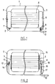
- Figure 1 shows two sides of a glazing according to the prior art.
- the glazing 1 has in this figure two electrical connections 2 and 3. It is, in this figure, a monolithic glazing comprising a network of thin wires of electric heating resistance 4. Each heating wire 4 is electrically connected to two strips collectors 5 and 6. They are, for example, made of silver paste deposited by screen printing. Their width depends on the electrical power of the glazing.
- the electrical connections 2 or 3 are, in general, constituted by a metal strip 7 or 8 welded to the ends of the collecting strips 5 and 6 respectively. The connections as well as the collector strips are located in the sealing zone delimited by the seal shown in 9.
- Element 2 is shown in the unconnected position, while element 3 is shown in the connected position.
- the end of the conductive part of a cable 10, housed in the bodywork bay, is for example plugged into the metal strip 8.
- This figure illustrates the relatively large area of the collecting strip in order to connect each heating wire 4 to the electrical connection 2 or 3.
- Figure 2 is a view from two possible sides of a glazing according to the invention. It is the same type of glazing as that illustrated in FIG. 1.
- the electrical connections 11 and 12 according to the invention are located near the heating wires 4 for the same position of the wiring 10 of the bodywork bay vis-à-vis glazing screw. This arrangement makes it possible to reduce the length of the collecting strips 5 and 6. Advantageously, their width also decreases, as illustrated in the figure, thus reducing the amount of silver paste used while improving the aesthetics of the glazing.
- the connection 11 is shown coated while the connection 12 is shown uncoated according to the position of the seal 9 and 15, shown in dotted lines in the figure.
- the electrical connection consists, for example, of a metal strip 13 capable of being plugged into the end of the conductive filaments 14 of the cable. It can also be a connection by welding or any other means. Advantageously, it is an ultrasonic welding.
- the conductive filaments 14 of the cable are in the form of wire (s) or flat braid (s).
- the metal strip 13 and the conductive filaments 14 can be left bare as illustrated in the figure by the position of the seal 9.
- the cable attached to the substrate here consists of conductive filaments 16 and a sheath 17.
- the latter follows the shape of the conductive filaments 16 in order, at the same time, to ensure a seal, to reduce the bulk and to avoid any dirt infiltrating between the conductive part 16 and the sheath.
- the sheath 17 preferably has a flat base to facilitate its fixing. It is preferably semi-cylindrical or flat depending on the shape of the conductive part of the cable. In order to ensure satisfactory sealing outside the sealing zone, as shown in the figure, it is preferably a polyurethane sheath.
- the coating 18 of the connection 11 is here shown in a trapezoidal shape in order to increase its surface in contact with the glazing. This coating also makes it possible to camouflage, while ensuring sealing, any play existing between the conductive filaments 16 of the cable and the sheath 17.
- the collecting strip 6 is here represented in the sealing zone delimited by the seal 15. It can, according to the invention, be situated outside this sealing zone. It is then covered with the same type of coating as the coating 18 of the connection 11. It may possibly be the same part.
- FIG. 3 represents an advantageous variant of the invention. Only part of the glazing is shown.
- the two header strips 5 and 6 are connected to the same cable 19.
- the cable 19 can also electrically connect one or more other accessories requiring an electrical supply. As an illustration, it connects a stop light 20 to an electrical power source. It can also connect an antenna, optical devices, etc.
- the glazing then only has one cable outlet, referenced at 21.
- the cable outlet 21 can, of course, be located anywhere on the glazing. It is here represented in the upper part of the glazing.
- An added piece 22 can optionally provide the junction between the various conductive parts coming from either side of the glazing.
- FIG 4 is a schematic view of a bottom of the windshield, outside the sealing area, represented by hatching and delimited by the seal 23.
- Thin wires of electric heating resistance 24 allow, for example , defrost the windshield area near the windscreen wipers.
- Two connections 25 electrically connect these wires 24 to an electrical power source via a cable 26 fixed on the substrate.
- FIG. 5 represents an advantageous variant according to which the surface of a collecting strip is reduced or eliminated.
- the conductive filaments of the cable form a metallic braid in direct electrical contact with at least one accessory supplied with electrical signals, for example the wires heating 4.
- a coating 28 of the electrical connections may possibly be provided. It can cover all or part of the connections, as shown in the figure, depending on the position of the seal, not shown.
- a collecting strip 29 can, for example, electrically connect all these heating wires.
- the cable of the invention then consists of conductive filaments 30 partially or totally covering the strip 29. A single connection between the strip 29 and the conductive filaments 30 is then necessary.
- the conductive filaments 30 may possibly be covered with a coating, not shown.
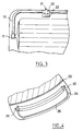
- FIG. 6 comprises four diagrams representing the cable fixed to the glazing according to the invention.
- the cable comes along the edge of the glazing at 31. It can be maintained by an adhesive tape 32, by fasteners or any other means. It can advantageously be embedded in the seal and, preferably, molded together.
- An attachment means advantageously maintains the cable at its curvature. This is, for example, a jumper as illustrated schematically in 33. This means also makes it possible to improve the aesthetics of the glazing and the tightness of the cable.
- the cable describes a radius of curvature on the peripheral part of the glazing.
- the radii of curvature here illustrated are sufficiently large for the adhesion of the cable to the glazing to be satisfactory at the level of the radius of curvature.
- the radii of curvature can also be smaller or the cable can describe sharp angles.
- the cable sheath is then advantageously molded or overmolded in the desired directions. It can also be extruded.
- the material used is preferably a foam.
- FIGs 6c and 6d Another solution is illustrated in diagrams 6c and 6d according to which the cable describes a sharp angle or a small radius of curvature, although the material used for its sheathing is not a foam.
- the cable consists, in addition to conductive filaments not shown, of two sheaths 34 and 35 superimposed on each other.
- the sheath 34 can be a standard, cylindrical, PVC sheath.
- the sheath 35 is exposed at the radius of curvature and reveals the sheath 34.
- the cable can then run on the glazing, as illustrated in diagram 6c or along the edge of the glazing, as illustrated in diagram 6d. It is advantageously glued to the surface of the substrate, according to diagram 6c and held by an adhesive tape or a fastener 32 according to diagram 6d.
- the sheath 35 may not be present when the cable extends along the glazing, as illustrated in diagram 6d.
- the size of the cable, in particular the height, is thus reduced. It is obvious that when the sheath 35 is exposed, the sheath 34 must have the appropriate properties, in particular sufficient sealing, in particular when the cable is located outside the sealing zone.
- Figure 7 shows a schematic section of a sheath 36 fixed to the glazing. It preferably comprises lips 37 making it possible both to improve its fixing to the glazing and to camouflage the bonding of the sheath. Two lips can be provided on either side of the sheath body, as illustrated. It is also possible to provide a single lip.
- This sheath 36 can coat the conductive filaments 38 of the cable. These conductive filaments can optionally be coated with a second sheath, not shown.
- These conductive filaments 38 can form several wires, as illustrated in diagram 7a. Each wire is made up of a multitude of conductive filaments. They can also form a single thread.
- the conductive filaments can be flat, as illustrated in diagram 7b.
- the sheath has a recess 39 capable of being filled with glue. The tightness of the conductive filaments of the cable is all the more improved. This glue may possibly overflow into the cavities 40 formed by the lips 37.
- Figure 8 shows a cable outlet on the glazing. It is a jumper 41, the shape of which makes it possible to overlap each of the faces of the glazing. It comprises a channel 42 into which a part of the cable according to the invention is inserted. The cable is thus securely held in the desired position at the exit of the glazing.
- the two wings 43 and 44 of the rider are shown here of unequal length. It goes without saying that they can be of identical length or that the wing 43 can be smaller than the wing 44.
- the dimensions of the cavity 45 formed by these two wings depend on the dimensions of the glazing. They may be such that they provide mechanical retention of the rider on the glazing. Glue can possibly be applied to improve this support.
- the material constituting this fixing means is preferably rigid.
- FIG. 9 represents another variant of cable outlet according to the invention. It is a connection element comprising a female lug into which the end 46 of the conductive filaments of the cable 47 of the invention can be inserted.
- a coating 48 allows, by its shape, both to maintain the cable in position and to improve the tightness of this electrical connection.
- a glue tank 49 is provided in order to seal the connection.
- the cable 50 is the cable which is intended to run in the bodywork bay.
- Figure 10 shows a section of the coating of the connection.
- a collar 51 makes it possible to provide the junction with a cable 52 and the connection.
- the cable 52 consists of conductive filaments 53 and two sheaths 54 and 55. Part of the sheath 54 is covered by the coating 56. Any possible play between the conductive part 53 and the sheath 54 is thus covered by the coating 56.
- the cable 52 can obviously only consist of a conductive part and a sheath or only of a bare conductive part.
- the cable 52 may possibly not be fixed to the substrate.
- the conductive part 53 is electrically connected to a metal strip 57 electrically connected to the accessories supplied with electrical signals. Once the connection with the two conductive parts 53 and 56 is ensured, the coating 55 is held in position by any means.
- the coating may have a semi-cylindrical, parallelepipedic or trapezoidal shape. Its base is adapted to the profile of the glazing. Advantageously, it deforms slightly under the effect of the injection of the glue, at high temperature, thus adapting perfectly to the profile of the glazing, in particular when it is curved.
- the width of its base is, for example, between 20 and 25 mm and its length is between 30 and 40 mm. These dimensions are obviously a compromise between a good bonding surface and a reduced bulk.
- this coating is advantageously molded and glued to the glazing. It can also be overmolded, possibly together with other functional elements and / or at least one seal.
- FIG. 11 represents a longitudinal section of a glazing according to the invention.
- the glass 59 is covered, on at least part of its periphery, with an enamel 60.
- This enamel hides from view the conductive part 61, generally of white color.
- a metal lug 62 is fixed in order to ensure an electrical connection.
- the coating 63 according to the invention makes it possible to camouflage both the conductive part 61 and the terminal 62.
- Such a coating, placed and fixed on the surface of a glazing can also provide sealing while camouflaging any conductive element, for example a conductive strip. It has the advantage of improving the aesthetics of the glazing while ensuring a perfect seal, in particular when glue is injected into its cavity.
- the conductive elements thus coated can be placed, for example outside the sealing zone.
- Figure 12 shows different types of profiled parts covering the conductive filaments 64 of the cable.
- the profiled part 65 is fixed on a base 66 supporting the conductive filaments 64.
- This base may include lugs 67 intended to cooperate with the lugs 68 of the part 65.
- the base is here shown glued using a adhesive layer 95.
- FIG. 13 represents a glazing whose cable crosses, at its exit from the glazing, the boundary between a sealing zone and an out of sealing zone.
- the cables 69 and 70 are respectively connected to two collecting strips 5, 6 made, for example, of silver-based paste deposited by screen printing. Each strip is connected to fine wires of electrical resistance 4 constituting a heating network.
- the cables 71 and 72 are, for their part, connected to a signaling light 20, for example a stop light.
- the coating 65 of the profiled part type, advantageously covers the cables situated outside the sealing zone delimited by the joint 73.
- the heating network and the collector strips 5 and 6 are located in the zone of watertightness referenced A.
- the cables for their part, are located outside the sealing zone, in the so-called out of sealing zone, referenced B, for example outside the vehicle.
- the part 74 ensures the passage of the cables from the outside of the vehicle, that is to say from the non-sealing area referenced B to the sealing area referenced C, here inside a bellows 75 in communication with the interior of the bodywork bay, area protected from external stresses and, in particular, from humidity.
- the references A, B and C respectively denote the interior of the vehicle, for example the passenger compartment, the exterior of the vehicle and the hidden space inside the body, in which all the cables circulate.
- the joint 73 delimits zones A and B in this figure, while zones B and C are delimited by the limit 76 of the bodywork opening.
- the passage from the interior to the exterior of the vehicle, that is to say from zone A to zone B, is preferably carried out thanks to the presence of a coating of the organic type described, for example , in the unpublished French patent application FR 93/09595, deposited on a conductive layer, for example a part 77, 78 of the collector strips 5 and 6 respectively.
- a bellows 75 can also be provided in order to guide the cable (s) in zone C at the desired location, in general towards a source of supply of electrical signals.
- the part 74 is fixed to the substrate by a mechanical anchoring between the part 74 and the coating 65.
- FIG 14 shows a section along line II of the insert 74 described in Figure 13.
- the electrical connections are shown here in the form of four cables 69, 70, 71 and 72.
- These four cables consist of a conductive wire 79, itself made up of conductive filaments, not shown, each wire 79 being coated with a sheath 80. It is, for example, a standard sheath marketed with the conductive wire. Of course, several insulated wires can be coated with the same sheath 80.
- a part of these cables 69, 70, 71 and 72 is embedded in an insert 74.
- This part 74 is made of a thermoplastic or thermosetting material having a tightness to water, even a satisfactory saline atmosphere.
- the material is a thermoplastic or thermosetting elastomer chosen, for example, from the following group: polyvinyl chloride, polyurethane, mixture of polyurethane and polyamide, rubber, in particular of the EPDM (Ethylene Propylene Diene Monomer) type.
- This part is, for example, molded around a part of the cables 69, 70, 71 and 72. The presence of moisture between the cables and the material constituting the part 74 is thus avoided.
- the part includes a bulge, here represented in the form of a flange 81 in order to ensure its fixing to a glazing by a mechanical anchoring.
- Mechanical anchoring can also be ensured by a recess, a projection, a recess, a stop, etc. and their complementary part respectively.
- the cables are shown here coated with a sheath. It may be a standard sheath, for example made of polyvinyl chloride, or a sheath 17, 35, 36 as shown, for example, in FIGS. 2, 6 and 7. They may also be, at less partially, devoid of this sheath depending on the intended use.
- the four cables can also be assembled in the same sheath, not shown, at their exit from the insert 74.
- FIG. 15 represents a sectional view, along line II-II, of FIG. 13.
- the coating 65 is hooked to a flange 81 secured to the part 74.
- the cables 69, 72 are here shown covered with a part 65, while the cables 70 and 71, connected to a signaling light 20, are not covered with such a part. They can possibly be coated with a sheath 17, 35, 36. It can be clearly seen in this diagram that the part 74 is not in contact with the substrate 83, avoiding the presence of an additional thickness on the latter.
- the auxiliary part 65 has a constriction 82 intended to hang on the flange 81.
- the part 65 is fixed to the substrate using, for example, an adhesive layer or an adhesive tape, not shown ( e).
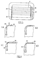
- FIG. 16 represents different variants, in section, of the insert 74 according to the invention.
- Part of the cable here consisting of a wire, is embedded in a part 74 according to the invention.
- this part comprises a collar 81 to which a coating 65 and a base 85 are attached.
- the two parts 65 and 85 are on the same face of the substrate 83.
- the substrate 83 can be, optionally coated with one or more layers, not shown. These parts can also be on the two opposite faces of the substrate 83.
- the base 85 is, for example, a base fixed on the substrate and supporting the connection 84. This base makes it possible, in particular, to overcome any deviations from glass sheet geometry.
- the part 74 is not in contact with the substrate 83.
- At least part of the part 74 is fixed to the substrate 83.
- the part 74 can be fixed using a bulge 86 and by a tab 87 fixed to the glass sheet (diagram 16b).
- the bulge 86 and the tab 87 can be on the two opposite faces of the substrate 83 (diagram 16b) or on the same face (diagram 16c).
- a part 88 of the part 74 can also be fixed on the substrate (diagram 16d).
- This part fixed to the substrate may possibly have a smaller thickness in order to ensure the passage of the connection under the seal 89.
- the connection ensuring this passage, 90 is then preferably a conductive layer, a strip of copper, a foil and / or a copper plate of the type used in printed circuits.
- a cable 91 can optionally provide the electrical connection in the area delimited by the gasket 89.
- FIG. 17 represents a profiled insert 74 comprising a lip 92 making it possible to ensure the continuity of a lip, not shown, which is also secured to a mounting joint.
- This lip not shown, provides protection, centering and maintenance of the glazing for the time necessary for the adhesive bead 93 fixing the glazing to the bay 94 of the bodywork.
- the bead of glue 93 may, if necessary, ensure the glazing / opening seal.
Abstract
Description
L'invention concerne un équipement destiné à relier électriquement au moins un accessoire supporté par un vitrage à un équipement hors vitrage, par exemple à une source d'alimentation électrique, à des capteurs, à une radio, etc... L'invention concerne également la liaison électrique proprement dite. L'invention concerne également le vitrage muni d'une telle liaison.The invention relates to equipment intended to electrically connect at least one accessory supported by a glazing unit to non-glazing equipment, for example to an electrical power source, to sensors, to a radio, etc. The invention relates to also the actual electrical connection. The invention also relates to glazing provided with such a connection.
Il existe différents types de vitrages nécessitant une connexion électrique. Il s'agit, par exemple, de vitrages chauffants, dégivrants, à propriétés optiques électrocommandées ou de vitrages équipés de capteurs, d'une antenne, d'un feu de signalisation, etc...There are different types of glazing that require an electrical connection. These are, for example, heated, de-icing glazing, with electrically controlled optical properties or glazing fitted with sensors, an antenna, a signaling light, etc.
Ces vitrages peuvent être utilisés dans le domaine des véhicules de transport, par exemple automobile, ferroviaire, aéronautique ou dans le domaine du bâtiment.These glazings can be used in the field of transport vehicles, for example automobile, rail, aeronautics or in the building field.
Usuellement, la liaison électrique, supportée par un substrat, entrant dans la constitution du vitrage est constituée d'un clinquant ou d'une couche conductrice, par exemple à base de pâte d'argent déposée notamment par sérigraphie. Cette liaison électrique est connectée, en bord de vitrage, à un câble situé en dehors du vitrage, relié à un équipement hors vitrage. Un joint d'étanchéité protège usuellement la liaison des sollicitations extérieures et notamment de l'humidité.Usually, the electrical connection, supported by a substrate, forming part of the glazing consists of a foil or a conductive layer, for example based on silver paste deposited in particular by screen printing. This electrical connection is connected, at the edge of the glazing, to a cable located outside the glazing, connected to equipment other than glazing. A seal usually protects the connection from external stresses and in particular from humidity.
Le substrat entrant dans la constitution du vitrage est au moins transparent en partie, ce peut être une feuille de verre, il peut être en verre organique ou minéral éventuellement revêtu d'une ou plusieurs couches minérales et/ou organiques. Il peut s'agir de couche(s) émaillée(s), de couches métalliques à base d'oxydes métalliques, notamment oxydes de zinc, ITO, SnO₂, SiO₂, Ag déposée(s), par exemple, par pyrolyse ou sous vide d'un revêtement organique, par exemple à base d'un organosilane et/ou d'un organosiloxane éventuellement fluoré(s).The substrate used in the constitution of the glazing is at least partly transparent, it can be a glass sheet, it can be made of organic or mineral glass optionally coated with one or more mineral and / or organic layers. It may be an enamelled layer (s), metal layers based on metal oxides, in particular zinc oxides, ITO, SnO₂, SiO₂, Ag deposited (s), for example, by pyrolysis or under vacuum. an organic coating, for example based on an organosilane and / or an optionally fluorinated organosiloxane (s).
Pour des raisons d'encombrement, le câble conduisant les signaux électriques est usuellement situé en dehors du vitrage au sein de la baie de carrosserie, par exemple. Par ailleurs, la connexion électrique entre la bande conductrice et le câble est généralement placée de telle sorte que la longueur du câble soit réduite. Ainsi pour un véhicule donné, par exemple, la position de la connexion sur le vitrage est imposée par l'emplacement du câble dans la baie de carrosserie.For reasons of space, the cable conducting the electrical signals is usually located outside the glazing within the bodywork bay, for example. Furthermore, the electrical connection between the conductive strip and the cable is generally placed so that the length of the cable is reduced. Thus for a given vehicle, for example, the position of the connection on the glazing is imposed by the location of the cable in the bodywork bay.
La position imposée de la connexion peut correspondre à une courbure du vitrage, il peut alors être malaisé d'effectuer la connexion électrique. Par ailleurs, la position imposée de la connexion ne correspond pas toujours à celle des éléments nécessitant cette liaison électrique. Il est alors nécessaire de relier ces deux positions par une bande conductrice, à base de pâte d'argent, par exemple. Cette bande conductrice est peu esthétique. En outre, le matériau utilisé est généralement onéreux.The imposed position of the connection can correspond to a curvature of the glazing, it can then be difficult to make the electrical connection. Furthermore, the imposed position of the connection does not always correspond to that of the elements requiring this electrical connection. It is then necessary to connect these two positions with a conductive strip, based on silver paste, for example. This conductive strip is not very aesthetic. In addition, the material used is generally expensive.
Par ailleurs, la puissance électrique qui peut acheminer une bande conductrice dépend notamment de sa largeur. Pour une largeur donnée, la puissance électrique ne peut excéder une certaine valeur. Cette limitation peut être gênante lorsque la largeur impartie pour la bande conductrice ne correspond pas à la puissance désirée pour le vitrage.Furthermore, the electrical power which can convey a conductive strip depends in particular on its width. For a given width, the electric power cannot exceed a certain value. This limitation can be troublesome when the width allocated for the conductive strip does not correspond to the desired power for the glazing.
La présente invention obvie à ces inconvénients.The present invention overcomes these drawbacks.
L'invention concerne un vitrage pouvant être alimenté avec une puissance électrique quelconque pour une largeur aussi petite que 2 mm.The invention relates to glazing which can be supplied with any electrical power for a width as small as 2 mm.
L'invention concerne, par ailleurs, un vitrage prêt à la monte.The invention further relates to glazing ready for fitting.
La présente invention concerne un vitrage équipé d'au moins un accessoire alimenté en signaux électriques à l'aide d'au moins un dispositif de liaison électrique comportant des éléments conducteurs, ledit dispositif étant constitué d'au moins un câble, au moins une partie du câble étant, selon l'invention, fixée au substrat entrant dans la constitution du vitrage.The present invention relates to a glazing unit fitted with at least one accessory supplied with electrical signals using at least one device for electrical connection comprising conductive elements, said device consisting of at least one cable, at least part of the cable being, according to the invention, fixed to the substrate forming part of the glazing.
On appelle câble, des filaments conducteurs susceptibles de transmettre des signaux électriques, éventuellement enrobés d'au moins une gaine, par exemple une gaine standard en polychlorure de polyvinyle.Cable is called conductive filaments capable of transmitting electrical signals, possibly coated with at least one sheath, for example a standard polyvinylchloride sheath.
La position de la connexion électrique du câble aux accessoires alimentés en signaux électriques peut être, selon l'invention, à tout endroit du substrat, quelle que soit la structure du véhicule. Elle est, de préférence, en périphérie du substrat et, de façon préférée, en bord de périphérie. Elle est avantageusement située dans la partie du substrat destinée à être cachée. De façon préférée, la connexion électrique est à proximité des accessoires alimentés en signaux électriques. Elle est, par exemple, située, pour une lunette arrière chauffante, sur le côté du vitrage destiné à être monté dans un montant, avantageusement au centre de ce côté. De ce fait, la longueur de la bande conductrice, à base de pâte d'argent par exemple, est ainsi limitée. Sa présence peut être avantageusement supprimée.According to the invention, the position of the electrical connection of the cable to the accessories supplied with electrical signals can be anywhere on the substrate, whatever the structure of the vehicle. It is preferably at the periphery of the substrate and, preferably, at the periphery edge. It is advantageously located in the part of the substrate intended to be hidden. Preferably, the electrical connection is near accessories supplied with electrical signals. It is, for example, located, for a heated rear window, on the side of the glazing intended to be mounted in an upright, advantageously in the center of this side. Therefore, the length of the conductive strip, based on silver paste for example, is thus limited. Its presence can advantageously be eliminated.
Le câble de l'invention peut être fixé en surface ou sur le chant du substrat. Il peut être situé au sein d'une zone protégée des sollicitations extérieures, par exemple au sein de la zone dite d'étanchéité, délimitée par un joint d'étanchéité. Il peut être également situé hors de cette zone d'étanchéité. C'est notamment le cas lorsqu'il s'agit d'un vitrage ouvrant, c'est-à-dire un vitrage qui s'ouvre indépendamment de l'ouverture d'une porte. Il est alors soumis aux sollicitations extérieures, telles que air, eau, solutions détergentes ainsi qu'aux chocs. Il peut également traverser, à sa sortie hors du vitrage, la limite entre deux zones, la zone dite d'étanchéité et la zone dite hors étanchéité.The cable of the invention can be fixed on the surface or on the edge of the substrate. It can be located within an area protected from external stresses, for example within the so-called sealing area, delimited by a seal. It can also be located outside this sealing zone. This is particularly the case when it is an opening glazing, that is to say a glazing which opens independently of the opening of a door. It is then subjected to external stresses, such as air, water, detergent solutions as well as to shocks. It can also cross, at its exit from the glazing, the boundary between two zones, the so-called sealing zone and the so-called non-sealing zone.
Le vitrage de l'invention peut comporter plusieurs accessoires alimentés en signaux électriques. Avantageusement, ces accessoires électriques sont connectées au même câble. Un même câble reliant électriquement plusieurs accessoires, le nombre de sorties de câbles est ainsi limité. Le vitrage de l'invention comporte, avantageusement, une unique sortie de câble.The glazing of the invention may include several accessories supplied with electrical signals. Advantageously, these electrical accessories are connected to the same cable. The same cable electrically connecting several accessories, the number of cable outlets is thus limited. The glazing unit of the invention advantageously comprises a single cable outlet.
Le câble de l'invention est fixé au substrat directement ou indirectement. Il peut être logé, par exemple, dans un enrobage lui-même fixé sur le substrat. Cette fixation peut être par soudure, à l'aide d'un ruban adhésif ou d'attaches. Il est avantageusement fixé par collage, notamment lorsqu'il est exposé à la vue. Il est, de préférence, collé à l'aide d'un ruban comportant, sur chacune de ses faces, une couche adhésive. Tout risque de débordement, dû notamment au fluage d'une colle, est ainsi éliminé. Par ailleurs, l'opération de collage est particulièrement facile à mettre en oeuvre.The cable of the invention is fixed to the substrate directly or indirectly. It can be housed, for example, in a coating itself fixed on the substrate. This fixing can be by welding, using an adhesive tape or fasteners. It is advantageously fixed by gluing, especially when exposed to view. It is preferably glued using a tape comprising, on each of its faces, an adhesive layer. Any risk of overflow, due in particular to the creep of an adhesive, is thus eliminated. Furthermore, the bonding operation is particularly easy to implement.
Afin de mieux épouser les variations de planéité et/ou de courbure éventuels du vitrage, le ruban adhésif est, de préférence, une mousse comportant sur chacune de ses faces une couche adhésive. Il s'agit, par exemple, d'une mousse du type acrylique ou du type polyuréthane.In order to better match the variations in flatness and / or possible curvature of the glazing, the adhesive tape is preferably a foam comprising on each of its faces an adhesive layer. It is, for example, a foam of the acrylic type or of the polyurethane type.
Avantageusement, après un nettoyage de la surface à encoller, un primaire est appliqué à la fois sur le vitrage et sur le câble. Le primaire appliqué sur le câble peut être du type polypropylène chloré comportant des groupements esters.Advantageously, after cleaning the surface to be bonded, a primer is applied to both the glazing and the cable. The primer applied to the cable can be of the chlorinated polypropylene type comprising ester groups.
Le primaire appliqué sur le verre peut être un mélange d'isopropanol, de mercaptosilanes et de diaminosilanes. Une deuxième couche de primaire à base d'isocyanate peut éventuellement être appliquée. Il peut s'agir également d'une résine à base d'un mélange vinyl-polyuréthane.The primer applied to the glass can be a mixture of isopropanol, mercaptosilanes and diaminosilanes. A second coat of isocyanate-based primer can optionally be applied. It can also be a resin based on a vinyl-polyurethane mixture.
L'adhésion du câble ou, éventuellement de son enrobage, sur le vitrage peut présenter une résistance supérieure ou égale à 5 N/cm mesuré selon le test dit de pelage à 90°. La valeur de la résistance est satisfaisante lorsque, notamment, le câble est soumis aux sollicitations extérieures.The adhesion of the cable or, possibly of its coating, to the glazing may have a resistance greater than or equal to 5 N / cm measured according to the so-called 90 ° peel test. The resistance value is satisfactory when, in particular, the cable is subjected to external stresses.
La forme du câble peut être semi-cylindrique ou cylindrique. Elle est avantageusement plate afin d'en limiter l'encombrement en hauteur. La forme du câble peut être fonction de la forme des filaments conducteurs : ils peuvent former une tresse plate ou au moins un fil.The shape of the cable can be semi-cylindrical or cylindrical. It is advantageously flat in order to limit its overall height. The shape of the cable can be a function of the shape of the conductive filaments: they can form a flat braid or at least one wire.
La connexion électrique entre le câble et les accessoires alimentés en signaux électrique est assurée par un contact électrique entre l'extrémité de la partie conductrice du câble et une partie conductrice reliée électriquement aux éléments. Ce contact peut être assuré par une soudure, avantageusement par ultrasons, l'enfichage de deux cosses ou tout autre moyen approprié. Selon un mode de réalisation de l'invention, les filaments conducteurs du câble sont en contact électrique direct avec au moins un accessoire alimenté en signaux électriques.The electrical connection between the cable and the accessories supplied with electrical signals is ensured by an electrical contact between the end of the conductive part of the cable and a conductive part electrically connected to the elements. This contact can be ensured by welding, advantageously by ultrasound, the insertion of two lugs or any other suitable means. According to a embodiment of the invention, the conductive filaments of the cable are in direct electrical contact with at least one accessory supplied with electrical signals.
Selon une variante avantageuse, au moins un élément conducteur du vitrage est recouvert par un enrobage. Cet enrobage peut permettre de cacher l'élément conducteur à la vue. Il protège en outre, en quelque sorte, I'élément conducteur de tout choc éventuel. Il s'agit, par exemple, d'un élément conducteur situé sur une des faces du substrat ou sur le chant du substrat, par exemple une bande conductrice, les filaments conducteurs du câble ou une connexion électrique. Il peut également assurer avantageusement l'étanchéité de l'élément conducteur lorsqu'il est situé hors de la zone d'étanchéité.According to an advantageous variant, at least one conductive element of the glazing is covered by a coating. This coating can hide the conductive element from view. It also protects, in a way, the conductive element from any possible shock. It is, for example, a conductive element located on one of the faces of the substrate or on the edge of the substrate, for example a conductive strip, the conductive filaments of the cable or an electrical connection. It can also advantageously seal the conductive element when it is located outside the sealing zone.
Le matériau constituant l'enrobage est choisi parmi les matériaux suivants : chlorure de polyvinyle, polyuréthane, EPDM (Ethylène Propylène Diène Monomère), polysulfure, polyamide ou un mélange de polyuréthane et de polyamide.The material constituting the coating is chosen from the following materials: polyvinyl chloride, polyurethane, EPDM (Ethylene Propylene Diene Monomer), polysulfide, polyamide or a mixture of polyurethane and polyamide.
De manière préférée, au moins une partie des filaments conducteurs du câble est noyée dans un enrobage. Cet enrobage, appelé gaine dans la suite de la description, peut être extrudée afin d'en limiter l'encombrement sur le vitrage. Elle peut également être moulée ou, avantageusement, surmoulée.Preferably, at least a portion of the conductive filaments of the cable is embedded in a coating. This coating, called sheath in the following description, can be extruded in order to limit the size on the glazing. It can also be molded or, advantageously, molded.
Le matériau constituant la gaine du câble doit être un isolant électrique et présenter une résistance mécanique suffisante pour ne pas être endommagé par tout heurt éventuel. Par ailleurs, il doit être étanche à l'eau et à une atmosphère saline, notamment lorsqu'il est exposé à l'atmosphère environnante. Il s'agit, par exemple, de chlorure de polyvinyle, de polyuréthane, d'un mélange de polyuréthane et de polyamide ou d'un caoutchouc, par exemple du type EPDM (Ethylène Propylène Diène Monomère). Il s'agit, par exemple, d'un polyuréthane. Afin d'améliorer sa fixation sur le vitrage, notamment lorsque la gaine est avantageusement collée, cette dernière présente selon l'invention une base plane. Afin d'obtenir une fixation satisfaisante, la largeur de sa base est avantageusement supérieure ou égale à 2 mm. Les dimensions de la base de la gaine sont évidemment un compromis entre, d'une part l'obtention d'une bonne adhésion et, d'autre part un encombrement réduit. La hauteur de la gaine peut être aussi petite que 5 mm, voire 2 mm. Deux gaines peuvent éventuellement être superposées l'une à l'autre. La gaine intérieure est, par exemple, une gaine standard, généralement commercialisée avec la partie conductrice du câble.The material constituting the cable sheath must be an electrical insulator and have sufficient mechanical resistance so as not to be damaged by any possible impact. Furthermore, it must be impermeable to water and to a saline atmosphere, in particular when it is exposed to the surrounding atmosphere. It is, for example, polyvinyl chloride, polyurethane, a mixture of polyurethane and polyamide or a rubber, for example of the EPDM (Ethylene Propylene Diene Monomer) type. It is, for example, a polyurethane. In order to improve its fixing to the glazing, in particular when the sheath is advantageously glued, the latter has, according to the invention, a flat base. In order to obtain a satisfactory fixing, the width of its base is advantageously greater than or equal to 2 mm. The dimensions of the base of the sheath are obviously a compromise between, on the one hand obtaining good adhesion and, on the other hand a reduced bulk. The height of the sheath can also be small than 5 mm or even 2 mm. Two sheaths can optionally be superimposed on each other. The inner sheath is, for example, a standard sheath, generally marketed with the conductive part of the cable.
Le câble selon l'invention peut présenter des changements de direction. Lorsque la gaine est extrudée, on utilise de préférence, selon l'invention, un matériau du type mousse afin d'obtenir une bonne adhésion au niveau de la courbure, notamment lorsque le rayon de courbure est court ou qu'il existe un angle vif. Les inventeurs ont ainsi montré qu'avec ce type de matériau, la surface de collage était la même au niveau des changements de direction qu'au niveau des segments droits. Une autre solution, selon les inventeurs, est d'utiliser un câble dont la gaine est coextrudée de manière à pouvoir, au niveau des changements de direction, mettre à nu la gaine intérieure de plus faible volume. L'utilisation d'un enrobage à deux gaines superposées permet, en outre, de fixer le câble dans des zones où l'encombrement du câble demande à être réduit, en déshabillant partiellement le câble tout en conservant ses caractéristiques isolantes.The cable according to the invention may have changes in direction. When the sheath is extruded, a foam-type material is preferably used according to the invention in order to obtain good adhesion at the level of the curvature, in particular when the radius of curvature is short or when there is a sharp angle. . The inventors have thus shown that with this type of material, the bonding surface was the same at the level of the changes of direction as at the level of the straight segments. Another solution, according to the inventors, is to use a cable whose sheath is coextruded so as to be able, at the level of changes of direction, to expose the inner sheath of smaller volume. The use of a coating with two superimposed sheaths also makes it possible to fix the cable in areas where the size of the cable needs to be reduced, by partially undressing the cable while retaining its insulating characteristics.
Le profil de la gaine de l'invention peut comporter, de préférence, au moins une lèvre venant s'appliquer sur le vitrage. L'aspect esthétique en est d'autant amélioré.The profile of the sheath of the invention may preferably include at least one lip which is applied to the glazing. The aesthetic aspect is all the more improved.
Un enrobage peut également être une pièce profilée recouvrant un élément conducteur, notamment une connexion électrique et/ou les filaments conducteurs du câble. Il chapeaute en quelque sorte l'élément conducteur. Cette dernière est, par exemple, située sur une partie plane ou courbe du vitrage. Ses dimensions sont fonction des dimensions de l'élément conducteur. Pour une connexion électrique, elles peuvent être calculées de manière à recouvrir un éventuel jeu entre la partie conductrice du câble et sa gaine. Elle peut également recouvrir au moins une partie de la bande conductrice, la masquant ainsi à la vue et/ou assurant son étanchéité. A titre indicatif, sa largeur est, par exemple, comprise entre 20 et 25 mm, sa longueur entre 30 et 40 mm et sa hauteur entre 3 et 5 mm. La pièce profilée peut avoir la forme d'un parallélépipède, d'un semi-cylindre ou, avantageusement, d'un trapèze : pour la même surface de base, assurant sa fixation, son encombrement est réduit. Toute autre forme peut également être envisagée ; avantageusement, l'élément conducteur, notamment les filaments conducteurs du câble, sont supportés par une embase afin d'obtenir à la fois un positionnement précis du câble et de s'affranchir de tout écart éventuel de géométrie du vitrage.A coating may also be a profiled part covering a conductive element, in particular an electrical connection and / or the conductive filaments of the cable. In a way, it oversees the conductive element. The latter is, for example, located on a flat or curved part of the glazing. Its dimensions are a function of the dimensions of the conductive element. For an electrical connection, they can be calculated so as to cover a possible clearance between the conductive part of the cable and its sheath. It can also cover at least part of the conductive strip, thus masking it from view and / or ensuring its sealing. As an indication, its width is, for example, between 20 and 25 mm, its length between 30 and 40 mm and its height between 3 and 5 mm. The profiled part can have the shape of a parallelepiped, a semi-cylinder or, advantageously, a trapezoid: for the same base surface, ensuring its fixing, its size is reduced. Any other form can also be considered; advantageously, the conductive element, in particular the conductive filaments of the cable, are supported by a base in order to obtain both precise positioning of the cable and to overcome any possible deviation in geometry of the glazing.
Le matériau constituant l'enrobage de la connexion électrique, d'une bande conductrice et/ou des filaments conducteurs du câble peut être identique à celui constituant la gaine du câble. Il peut s'agir également d'un autre matériau. Il s'agit, par exemple, ce chlorure de polyvinyle, de polyuréthane, de polysulfure ou de polyamide, de préférence renforcé. L'enrobage de la connexion et/ou d'une bande conductrice et du câble ne peuvent former qu'une pièce, notamment si cet enrobage est surmoulé. Ils peuvent également former plusieurs pièces distinctes, de préférence lorsqu'il s'agit de plusieurs pièces usinées ou moulées, collées sur le vitrage.The material constituting the coating of the electrical connection, a conductive strip and / or the conductive filaments of the cable may be identical to that constituting the sheath of the cable. It may also be another material. It is, for example, this polyvinyl chloride, polyurethane, polysulfide or polyamide, preferably reinforced. The coating of the connection and / or of a conductive strip and of the cable can only form a single part, in particular if this coating is overmolded. They can also form several separate parts, preferably in the case of several machined or molded parts, glued to the glazing.
Selon une variante avantageuse, l'enrobage de l'élément conducteur assure son étanchéité. Il peut, par exemple, être situé hors de la zone d'étanchéité, délimitée par un joint d'étanchéité et être ainsi soumis aux sollicitations extérieures.According to an advantageous variant, the coating of the conductive element ensures its sealing. It can, for example, be located outside the sealing zone, delimited by a seal and thus be subjected to external stresses.
Une colle est alors avantageusement injectée à l'intérieur de la cavité formée par la pièce profilée, afin d'assurer son étanchéité. Elle assure également avantageusement son adhésion. Un primaire peut être appliqué sur le vitrage préalablement à l'encollage. Il s'agit, par exemple, d'une colle du type thermofusible, de préférence du type polyamide. L'enrobage peut, éventuellement, servir de moule, étant enlevé par la suite.An adhesive is then advantageously injected inside the cavity formed by the profiled part, in order to ensure its sealing. It also advantageously ensures its adhesion. A primer can be applied to the glazing before gluing. It is, for example, an adhesive of the hot-melt type, preferably of the polyamide type. The coating may possibly serve as a mold, being removed thereafter.
L'invention concerne également un moyen pour éviter toute infiltration d'humidité dans la zone d'étanchéité lorsque, notamment, le câble traverse, à sa sortie hors du vitrage, la limite entre la zone dite hors étanchéité et la zone d'étanchéité. C'est notamment le cas lorsque le câble est en dehors de la zone délimitée par un joint d'étanchéité, la source d'alimentation en signaux électriques étant, quant à elle, dans une zone protégée des sollicitations extérieures par un joint d'étanchéité. Cette configuration se trouve, par exemple, lorsque le vitrage et ouvrant, c'est-à-dire qu'il est susceptible de s'ouvrir indépendamment de l'ouverture d'une porte. Le câble peut alors conduire à une pénétration d'humidité dans la zone dite d'étanchéité. Or, les équipements dans cette zone ne sont pas nécessairement revêtus d'une protection étanche.The invention also relates to a means for preventing any infiltration of moisture into the sealing zone when, in particular, the cable crosses, at its exit from the glazing, the boundary between the so-called out of sealing zone and the sealing zone. This is particularly the case when the cable is outside the zone delimited by a seal, the source of supply of electrical signals being, for its part, in a zone protected from external stresses by a seal. . This configuration is found, for example, when the glazing and opening, that is to say that it is capable of opening independently of the opening of a door. The cable can then lead to moisture penetration into the so-called sealing zone. However, the equipment in this area is not necessarily covered with waterproof protection.
Selon une variante avantageuse, la partie du câble traversant à sa sortie hors du vitrage la limite entre la zone d'étanchéité et la zone hors étanchéité est noyée dans une pièce rapportée comportant un moyen de fixation destiné à la fixer sur le substrat.According to an advantageous variant, the part of the cable passing at its exit from the glazing the boundary between the sealing zone and the non-sealing zone is embedded in an attached part comprising a fixing means intended to fix it on the substrate.
Le moyen de fixation peut être une partie ou une patte solidaire de la pièce rapportée, cette partie ou cette patte étant destinée à être fixée sur le substrat notamment par collage. Elles peuvent également être fixées à l'aide d'un ruban adhésif comportant éventuellement sur chacune de ses faces une couche adhésive, une attache tel qu'un cavalier ou tout autre moyen adéquat. Selon une variante avantageuse, le moyen de fixation est un ancrage mécanique entre la pièce rapportée et une pièce auxiliaire, elle-même fixée sur le substrat. La pièce peut ainsi ne pas être en contact avec le vitrage, évitant ainsi toute surépaisseur. Selon une variante particulièrement avantageuse, cette pièce auxiliaire constitue l'enrobage d'un élément conducteur, notamment d'une partie du câble située hors de la zone d'étanchéité. Elle peut alors cacher la liaison électrique à la vue. Elle peut également éventuellement assurer, ou du moins améliorer, son étanchéité. D'autre part, sa présence permet de s'affranchir de tout écart éventuel relatif à la dimension de la liaison électrique. La pièce rapportée de l'invention peut également être fixée au substrat à l'aide d'un ancrage mécanique et, d'une partie ou d'une patte, fixée au vitrage.The fixing means may be a part or a tab integral with the insert, this part or this tab being intended to be fixed to the substrate in particular by bonding. They can also be fixed using an adhesive tape optionally comprising on each of its faces an adhesive layer, a fastener such as a jumper or any other suitable means. According to an advantageous variant, the fixing means is a mechanical anchoring between the insert and an auxiliary part, itself fixed on the substrate. The part may thus not be in contact with the glazing, thus avoiding any excess thickness. According to a particularly advantageous variant, this auxiliary part constitutes the coating of a conductive element, in particular of a part of the cable situated outside the sealing zone. She can then hide the electrical connection from view. It can also possibly ensure, or at least improve, its sealing. On the other hand, its presence makes it possible to overcome any possible deviation relating to the dimension of the electrical connection. The insert of the invention can also be fixed to the substrate using a mechanical anchoring and, partly or a tab, fixed to the glazing.
L'ancrage mécanique est assuré, de préférence, par un renflement sur l'une des pièces, la pièce rapportée ou la pièce auxiliaire, l'autre pièce comportant la partie complémentaire.The mechanical anchoring is ensured, preferably, by a bulge on one of the parts, the insert or the auxiliary part, the other part comprising the complementary part.
La pièce rapportée de l'invention peut comporter d'autres fonctions que celles inhérentes à l'étanchéité du câble noyé en son sein. Elle peut, par exemple, comporter des moyens de fixation pour un rétroviseur, des moyens pour une alimentation en air ou en eau ou toute autre fonction dans la mesure où cette fonction est nécessaire à l'endroit du vitrage où sort la liaison électrique hors du vitrage. La pièce rapportée de l'invention comporte, avantageusement, une lèvre destinée à assurer la continuité d'une lèvre solidaire, par ailleurs, d'un joint de montage facilitant le montage du vitrage dans une baie.The insert of the invention may include other functions than those inherent in the sealing of the cable embedded therein. It may, for example, include fixing means for a rear-view mirror, means for supplying air or water or any other function insofar as this function is necessary at the location of the glazing where the electrical connection exits the glazing. The insert of the invention advantageously comprises a lip intended to ensure the continuity of a lip integral, moreover, with a mounting joint facilitating the mounting of the glazing in a bay.
La pièce rapportée peut être préfabriquée, rapportée et fixée sur le substrat entrant dans la constitution du vitrage. Elle est, par exemple, moulée autour d'une partie d'une liaison électrique, rapportée et fixée sur le substrat. Elle peut également être moulée directement sur le substrat muni de ladite liaison électrique.The insert can be prefabricated, attached and fixed to the substrate used to make up the glazing. It is, for example, molded around part of an electrical connection, attached and fixed to the substrate. It can also be molded directly on the substrate provided with said electrical connection.
La technique de moulage permet, en particulier, d'obtenir des dimensions relativement petites tout en étant précises, ce qui permet de limiter l'encombrement de la pièce rapportée sur le vitrage. Les dimensions de la pièce rapportée sont fonction de l'utilisation envisagée. La hauteur de la pièce dépend, notamment, de la nature de la liaison surmoulée. Elle peut être aussi petite que 2 mm. Sa largeur dépend également de la largeur de la liaison et, éventuellement, du nombre de fils présents. Elle est, par exemple, comprise entre 4 et 100 mm. Sa longueur est, par exemple, comprise entre 4 et 100 mm.The molding technique makes it possible, in particular, to obtain relatively small dimensions while being precise, which makes it possible to limit the size of the insert on the glazing. The dimensions of the insert depend on the intended use. The height of the part depends, in particular, on the nature of the overmolded connection. It can be as small as 2mm. Its width also depends on the width of the link and, optionally, on the number of wires present. It is, for example, between 4 and 100 mm. Its length is, for example, between 4 and 100 mm.
La suite de la description a trait, de façon plus détaillée, au vitrage selon l'invention en référence aux figures dans lesquelles:
- · la figure 1 représente une vue partielle de dessus de deux côtés d'un vitrage de l'art antérieur,
- · la figure 2 représente une vue partielle de dessus de deux côtés d'un vitrage selon l'invention,
- · la figure 3 représente une deuxième variante d'un vitrage selon l'invention, vue de dessus,
- · la figure 4 représente une troisième variante d'un vitrage selon l'invention, vue de dessus,
- · la figure 5 représente une quatrième variante d'un vitrage selon l'invention, vue de dessus,
- · la figure 6 comporte quatre schémas représentant le câble selon l'invention, vu de dessus,
- · la figure 7 comporte deux schémas de profils de la gaine du câble, selon une coupe longitudinale,
- · la figure 8 représente, plus en détail, une sortie de câble selon l'invention, en perspective,
- · la figure 9 représente une deuxième sortie de câble selon l'invention, selon une coupe schématique longitudinale,
- · la figure 10 représente un schéma en perspective de l'enrobage d'une connexion électrique,
- · la figure 11 représente une coupe schématique longitudinale de l'enrobage d'une connexion électrique fixée sur le vitrage
- · la figure 12 représente, en coupe, des enrobages, du type pièces profilées, les filaments conducteurs du câble étant supportés par des embases,
- · la figure 13 représente un vitrage dont le câble traverse, à sa sortie, la limite entre la zone d'étanchéité et la zone hors étanchéité,
- · la figure 14 représente une coupe selon la ligne I-I de la pièce rapportée décrite sur la figure 13,
- · la figure 15 représente une coupe selon la ligne II-II de la pièce rapportée décrite sur la figure 13,
- · la figure 16 représente cinq schémas 16a à 16d, en coupe, d'une pièce rapportée de l'invention,
- · la figure 17 représente, en coupe, une pièce rapportée munie d'une lèvre.
- FIG. 1 represents a partial top view of two sides of a glazing unit of the prior art,
- FIG. 2 represents a partial top view of two sides of a glazing according to the invention,
- FIG. 3 represents a second variant of a glazing according to the invention, seen from above,
- FIG. 4 represents a third variant of a glazing according to the invention, seen from above,
- FIG. 5 represents a fourth variant of a glazing according to the invention, seen from above,
- FIG. 6 comprises four diagrams representing the cable according to the invention, seen from above,
- FIG. 7 comprises two diagrams of profiles of the cable sheath, in a longitudinal section,
- FIG. 8 represents, in more detail, a cable outlet according to the invention, in perspective,
- FIG. 9 represents a second cable outlet according to the invention, in a longitudinal schematic section,
- FIG. 10 represents a perspective diagram of the coating of an electrical connection,
- · Figure 11 shows a schematic longitudinal section of the coating of an electrical connection fixed to the glazing
- FIG. 12 represents, in section, coatings, of the profiled parts type, the conductive filaments of the cable being supported by bases,
- FIG. 13 represents a glazing whose cable crosses, at its exit, the boundary between the sealing zone and the non-sealing zone,
- FIG. 14 represents a section along line II of the insert described in FIG. 13,
- FIG. 15 represents a section along line II-II of the insert described in FIG. 13,
- FIG. 16 represents five diagrams 16a to 16d, in section, of an added part of the invention,
- · Figure 17 shows, in section, an insert with a lip.
La figure 1 représente deux côtés d'un vitrage selon l'art antérieur.Figure 1 shows two sides of a glazing according to the prior art.
Le vitrage 1 comporte sur cette figure deux connexions électriques 2 et 3. Il s'agit, sur cette figure, d'un vitrage monolithique comportant un réseau de fils fins de résistance électrique chauffants 4. Chaque fil chauffant 4 est relié électriquement à deux bandes collectrices 5 et 6. Elles sont, par exemple, constituées de pâte d'argent déposée par sérigraphie. Leur largeur est fonction de la puissance électrique du vitrage. Les connexions électriques 2 ou 3 sont, en général, constituées d'une bande métallique 7 ou 8 soudée aux extrémités des bandes collectrices 5 et 6 respectivement. Les connexions ainsi que les bandes collectrices sont situées dans la zone d'étanchéité délimitée par le joint d'étanchéité représenté en 9.The
L'élément 2 est représenté en position non connectée, alors que l'élément 3 est représenté en position connectée.
L'extrémité de la partie conductrice d'un câble 10, logé dans la baie de carrosserie, est par exemple enfichée à la bande métallique 8.The end of the conductive part of a
Cette figure illustre la surface relativement importante de la bande collectrice afin de relier chaque fil chauffant 4 à la connexion électrique 2 ou 3.This figure illustrates the relatively large area of the collecting strip in order to connect each
La figure 2 est une vue de deux côtés possibles d'un vitrage selon l'invention. Il s'agit du même type de vitrage que celui illustré figure 1. Les connexions électriques 11 et 12 selon l'invention, sont situées à proximité des fils chauffants 4 pour la même position du câblage 10 de la baie de carrosserie vis-à-vis du vitrage. Cette disposition permet de réduire la longueur des bandes collectrices 5 et 6. Avantageusement, leur largeur décroît également, comme illustré sur la figure, réduisant ainsi la quantité de pâte d'argent utilisée tout en améliorant l'esthétique du vitrage. La connexion 11 est représentée enrobée alors que la connexion 12 est représentée non enrobée d'après la position du joint d'étanchéité 9 et 15, représentés en pointillé sur la figure.Figure 2 is a view from two possible sides of a glazing according to the invention. It is the same type of glazing as that illustrated in FIG. 1. The
La connexion électrique est constituée, par exemple, d'une bande métallique 13 susceptible de venir s'enficher à l'extrémité des filaments conducteurs 14 du câble. Il peut s'agir également d'une connexion par soudure ou de tout autre moyen. Avantageusement, il s'agit d'une soudure par ultrasons. Les filaments conducteurs 14 du câble sont sous forme de fil(s) ou de tresse(s) plate(s). La bande métallique 13 et les filaments conducteurs 14 peuvent être laissés nus comme illustré sur la figure de par la position du joint d'étanchéité 9.The electrical connection consists, for example, of a
De par la position du joint d'étanchéité 15, la connexion 11 ainsi que les filaments conducteurs 16 du câble sont enrobées. Le câble fixé au substrat est ici constitué de filaments conducteurs 16 et d'une gaine 17. Cette dernière épouse la forme des filaments conducteurs 16 afin, à la fois, d'assurer une étanchéité, de réduire l'encombrement et d'éviter toute salissure s'infiltrant entre la partie conductrice 16 et la gaine. La gaine 17 comporte, de préférence, une base plate afin de faciliter sa fixation. Elle est, de préférence, semi-cylindrique ou plate selon la forme de la partie conductrice du câble. Afin d'assurer une étanchéité satisfaisante en dehors de la zone d'étanchéité, comme représenté sur la figure, il s'agit, de préférence, d'une gaine en polyuréthane.By the position of the
L'enrobage 18 de la connexion 11 est ici représenté de forme trapézoïdale afin d'augmenter sa surface en contact avec le vitrage. Cet enrobage permet, par ailleurs, de camoufler, tout en assurant l'étanchéité, un éventuel jeu existant entre les filaments conducteurs 16 du câble et la gaine 17.The
Par ailleurs, la bande collectrice 6 est ici représentée dans la zone d'étanchéité délimitée par le joint 15. Elle peut, selon l'invention, se situer en dehors de cette zone d'étanchéité. Elle est alors recouverte du même type d'enrobage que l'enrobage 18 de la connexion 11. Il peut s'agir éventuellement de la même pièce.Furthermore, the collecting
La figure 3 représente une variante avantageuse de l'invention. Seule une partie du vitrage est représentée. Les deux bandes collectrices 5 et 6 sont connectées au même câble 19. Le câble 19 peut également relier électriquement un ou plusieurs autres accessoires nécessitant une alimentation électrique. A titre illustratif, il relie un feu-stop 20 à une source d'alimentation électrique. Il peut également relier une antenne, des dispositifs optiques... Le vitrage ne comporte alors qu'une sortie de câble, référencée en 21. La sortie de câble 21 peut, bien entendu, se situer en tout endroit sur le vitrage. Elle est ici représentée en partie haute du vitrage. Une pièce rapportée 22 peut, éventuellement, assurer la jonction entre les différentes parties conductrices provenant de part et d'autre du vitrage.FIG. 3 represents an advantageous variant of the invention. Only part of the glazing is shown. The two
La figure 4 est une vue schématique d'un bas de pare-brise, hors de la zone d'étanchéité, représentée par des hachures et délimité par le joint d'étanchéité 23. Des fils fins de résistance électrique chauffants 24 permettent, par exemple, de dégivrer la zone du pare-brise à proximité des essuie-glaces. Deux connexions 25 relient électriquement ces fils 24 à une source d'alimentation électrique via un câble 26 fixé sur le substrat.Figure 4 is a schematic view of a bottom of the windshield, outside the sealing area, represented by hatching and delimited by the
La figure 5 représente une variante avantageuse selon laquelle la surface d'une bande collectrice est réduite ou supprimée. Les filaments conducteurs du câble forment une tresse métallique en contact électrique direct avec au moins un accessoire alimenté en signaux électriques, par exemple les fils chauffants 4. Un enrobage 28 des connexions électriques peut éventuellement être prévu. Il peut recouvrir toutes ou une partie des connexions, comme représenté sur la figure, selon la position du joint d'étanchéité non représenté.FIG. 5 represents an advantageous variant according to which the surface of a collecting strip is reduced or eliminated. The conductive filaments of the cable form a metallic braid in direct electrical contact with at least one accessory supplied with electrical signals, for example the
Afin d'éviter une connexion électrique pour chaque fil chauffant 4 à la tresse 27, une bande collectrice 29 peut, par exemple, relier électriquement tous ces fils chauffants. Le câble de l'invention est alors constitué de filaments conducteurs 30 recouvrant partiellement ou totalement la bande 29. Une seule connexion entre la bande 29 et les filaments conducteurs 30 est alors nécessaire. Les filaments conducteurs 30 peuvent éventuellement être recouverte d'un enrobage non représenté.In order to avoid an electrical connection for each
La figure 6 comporte quatre schémas représentant le câble fixé au vitrage selon l'invention. Sur le schéma 6a, le câble vient longer le chant du vitrage en 31. Il peut être maintenu par un ruban adhésif 32, par des attaches ou tout autre moyen. Il peut être avantageusement noyé dans le joint d'étanchéité et, de préférence, surmoulé conjointement. Un moyen de fixation maintient avantageusement le câble au niveau de sa courbure. Il s'agit, par exemple, d'un cavalier comme illustré schématiquement en 33. Ce moyen permet, en outre, d'améliorer l'esthétique du vitrage et l'étanchéité du câble. Sur le schéma 6b, le câble décrit un rayon de courbure sur la partie périphérique du vitrage. Les rayons de courbure ici illustrés sont suffisamment importants pour que l'adhésion du câble sur le vitrage soit satisfaisante au niveau du rayon de courbure. Les rayons de courbure peuvent également être plus petits ou encore le câble peut décrire des angles vifs. La gaine du câble est alors avantageusement moulée ou surmoulée selon les directions voulues. Elle peut être également extrudée. Dans ce cas, le matériau utilisé est, de préférence, une mousse.FIG. 6 comprises four diagrams representing the cable fixed to the glazing according to the invention. In diagram 6a, the cable comes along the edge of the glazing at 31. It can be maintained by an
Une autre solution est illustrée dans les schémas 6c et 6d selon laquelle le câble décrit un angle vif ou un petit rayon de courbure, bien que le matériau utilisé pour son gainage ne soit pas une mousse. Le câble est constitué, outre de filaments conducteurs non représentés, de deux gaines 34 et 35 superposées l'une à l'autre. La gaine 34 peut être une gaine standard, cylindrique, en PVC. La gaine 35 est mise à nu au niveau du rayon de courbure et fait apparaître la gaine 34. Le câble peut alors courir sur le vitrage, comme illustré sur le schéma 6c ou le long du chant du vitrage, comme illustré sur le schéma 6d. Elle est avantageusement collée sur la surface du substrat, selon le schéma 6c et maintenue par un ruban adhésif ou une attache 32 selon le schéma 6d. La gaine 35 peut ne pas être présente lorsque le câble s'étend le long du vitrage, comme illustré sur le schéma 6d. L'encombrement du câble, notamment er hauteur, est ainsi réduit. Il est évident que lorsque la gaine 35 est mise à nu, la gaine 34 doit présenter les propriétés adéquates, notamment une étanchéité suffisante, notamment lorsque le câble est situé hors zone d'étanchéité.Another solution is illustrated in diagrams 6c and 6d according to which the cable describes a sharp angle or a small radius of curvature, although the material used for its sheathing is not a foam. The cable consists, in addition to conductive filaments not shown, of two
La figure 7 représente une coupe schématique d'une gaine 36 fixée sur le vitrage. Elle comporte, de préférence, des lèvres 37 permettant, à la fois d'améliorer sa fixation sur le vitrage et de camoufler le collage de la gaine. Deux lèvres peuvent être prévues de part et d'autre du corps de la gaine, comme illustré. Il est également possible de prévoir une seule lèvre. Cette gaine 36 peut enrober les filaments conducteurs 38 du câble. Ces filaments conducteurs peuvent, éventuellement, être eux-mêmes enrobés d'une seconde gaine non représentée.Figure 7 shows a schematic section of a
Ces filaments conducteurs 38 peuvent former plusieurs fils, comme illustré sur le schéma 7a. Chaque fil est constitué d'une multitude de filaments conducteurs. lls peuvent également ne former qu'un fil. Les filaments conducteurs peuvent être plats, comme illustré sur le schéma 7b. Sur le schéma 7b, la gaine comporte un évidement 39 susceptible d'être rempli de colle. L'étanchéité des filaments conducteurs du câble en est d'autant améliorée. Cette colle peut, éventuellement, déborder dans les cavités 40 formées par les lèvres 37.These
La figure 8 représente une sortie de câble sur le vitrage. Il s'agit d'un cavalier 41 dont la forme permet de chevaucher chacune des faces du vitrage. Il comporte un canal 42 dans lequel est insérée une partie du câble selon l'invention. Le câble est ainsi solidement maintenu à la position voulue en sortie de vitrage. Les deux ailes 43 et 44 du cavalier sont ici représentées de longueur inégale. Il va de soi qu'elles peuvent être de longueur identique ou que l'aile 43 peut être plus petite que l'aile 44. Les dimensions de la cavité 45 formée par ces deux ailes sont fonction des dimensions du vitrage. Elles peuvent être telles qu'elles assurent un maintien mécanique du cavalier sur le vitrage. De la colle peut éventuellement être appliquée afin d'améliorer ce maintien. Le matériau constituant ce moyen de fixation est, de préférence, rigide.Figure 8 shows a cable outlet on the glazing. It is a
La figure 9 représente une autre variante de sortie de câble selon l'invention. II s'agit d'un élément de connexion comportant une cosse femelle dans laquelle peut s'enficher l'extrémité 46 des filaments conducteurs du câble 47 de l'invention. Un enrobage 48 permet, de par sa forme, à la fois de maintenir le câble en position et d'améliorer l'étanchéité de cette connexion électrique. Un réservoir à colle 49 est prévu afin d'assurer l'étanchéité de la connexion. Le câble 50 est le câble qui est destiné à courir dans la baie de carrosserie.FIG. 9 represents another variant of cable outlet according to the invention. It is a connection element comprising a female lug into which the
La figure 10 représente une coupe de l'enrobage de la connexion. Une collerette 51 permet d'assurer la jonction avec un câble 52 et la connexion. Le câble 52 est constitué de filaments conducteurs 53 et de deux gaines 54 et 55. Une partie de la gaine 54 est recouverte par l'enrobage 56. Tout jeu éventuel entre la partie conductrice 53 et la gaine 54 est ainsi recouvert par l'enrobage 56. Le câble 52 peut évidemment n'être constitué que d'une partie conductrice et une gaine ou que d'une partie conductrice nue. Le câble 52 peut, éventuellement, ne pas être fixé au substrat. La partie conductrice 53 est connectée électriquement à une bande métallique 57 reliée électriquement aux accessoires alimentés en signaux électriques. Une fois la connexion avec les deux parties conductrices 53 et 56 assurée, l'enrobage 55 est maintenu en position par tout moyen. De la colle est injectée par le trou d'injection 58 assurant l'étanchéité de la connexion et, le cas échéant, I'adhésion de l'enrobage 56 sur le vitrage. L'enrobage peut avoir une forme semi-cylindrique, parallélépipédique ou trapézoïdale. Sa base est adaptée au profil du vitrage. Avantageusement, elle se déforme légèrement sous l'effet de l'injection de la colle, à haute température, s'adaptant ainsi parfaitement au profil du vitrage, notamment lorsqu'il est courbe. La largeur de sa base est, par exemple, comprise entre 20 et 25 mm et sa longueur est comprise entre 30 et 40 mm. Ces dimensions sont évidemment un compromis entre une bonne surface de collage et un encombrement réduit. Afin de bien délimiter son encombrement, cet enrobage est avantageusement moulé et collé sur le vitrage. Il peut également être surmoulé, éventuellement conjointement à d'autres éléments fonctionnels et/ou à au moins un joint d'étanchéité.Figure 10 shows a section of the coating of the connection. A
La figure 11 représente une coupe longitudinale d'un vitrage selon l'invention. Le verre 59 est recouvert, sur au moins une partie de sa périphérie, d'un émail 60. Cet émail cache à la vue la partie conductrice 61, généralement de couleur blanche. Sur cette partie conductrice 61, est fixée une cosse métallique 62 afin d'assurer une connexion électrique. L'enrobage 63 selon l'invention permet de camoufler à la fois la partie conductrice 61 et la cosse 62.FIG. 11 represents a longitudinal section of a glazing according to the invention. The
Un tel enrobage, posé et fixé sur la surface d'un vitrage, peut également assurer l'étanchéité tout en camouflant tout élément conducteur, par exemple une bande conductrice. Il présente l'avantage d'améliorer l'esthétique du vitrage tout en assurant une parfaite étanchéité, notamment lorsque de la colle est injectée au sein de sa cavité. Les éléments conducteurs ainsi enrobés peuvent être placés, par exemple hors de la zone d'étanchéité.Such a coating, placed and fixed on the surface of a glazing, can also provide sealing while camouflaging any conductive element, for example a conductive strip. It has the advantage of improving the aesthetics of the glazing while ensuring a perfect seal, in particular when glue is injected into its cavity. The conductive elements thus coated can be placed, for example outside the sealing zone.
La figure 12 représente différents types de pièces profilées recouvrant les filaments conducteurs 64 du câble. La pièce profilée 65 vient se fixer sur une embase 66 supportant les filaments conducteurs 64. Cette embase peut comporter des ergots 67 destinés à coopérer avec les ergots 68 de la pièce 65. L'embase est ici représentée collée à l'aide d'une couche adhésive 95.Figure 12 shows different types of profiled parts covering the
La figure 13 représente un vitrage dont le câble traverse, à sa sortie du vitrage, la limite entre une zone d'étanchéité et une zone hors étanchéité.FIG. 13 represents a glazing whose cable crosses, at its exit from the glazing, the boundary between a sealing zone and an out of sealing zone.
Sur cette figure, les câbles 69 et 70 sont connectés respectivement à deux bandes collectrices 5, 6 constituées, par exemple, de pâte à base d'argent déposée par sérigraphie. Chaque bande est connectée à des fils fins de résistance électrique 4 constituant un réseau chauffant.In this figure, the
Les câbles 71 et 72 sont, quant à eux, connectés à un feu de signalisation 20, par exemple un feu-stop. L'enrobage 65, du type pièce profilée, recouvre avantageusement les câbles situés en dehors de la zone d'étanchéité délimitée par le joint 73. Sur cette figure, le réseau chauffant et les bandes collectrices 5 et 6 sont situés dans la zone d'étanchéité référencée A.The
Les câbles, quant à eux, sont situés en dehors de la zone d'étanchéité, dans la zone dite hors étanchéité, référencée B, par exemple à l'extérieur du véhicule. La pièce 74 assure le passage des câbles de l'extérieur du véhicule, c'est-à-dire de la zone hors étanchéité référencée B à la zone d'étanchéité référencée C, ici à l'intérieur d'un soufflet 75 en communication avec l'intérieur de la baie de carrosserie, zone protégée des sollicitations extérieures et, notamment, de l'humidité.The cables, for their part, are located outside the sealing zone, in the so-called out of sealing zone, referenced B, for example outside the vehicle. The
Les références A, B et C désignent respectivement l'intérieur du véhicule, par exemple l'habitacle, I'extérieur du véhicule et l'espace caché intérieur à la carrosserie, dans lequel circulent tous les câbles. Le joint 73 délimite sur cette figure les zones A et B, alors que les zones B et C sont délimitées par la limite 76 de la baie de carrosserie.The references A, B and C respectively denote the interior of the vehicle, for example the passenger compartment, the exterior of the vehicle and the hidden space inside the body, in which all the cables circulate. The joint 73 delimits zones A and B in this figure, while zones B and C are delimited by the
Le passage de l'intérieur à l'extérieur du véhicule, c'est-à-dire de la zone A à la zone B, est effectué, de préférence, grâce à la présence d'un enduit du type organique décrit, par exemple, dans la demande de brevet française non publiée FR 93/09595, déposé sur une couche conductrice, par exemple une partie 77, 78 des bandes collectrices 5 et 6 respectivement.The passage from the interior to the exterior of the vehicle, that is to say from zone A to zone B, is preferably carried out thanks to the presence of a coating of the organic type described, for example , in the unpublished French
L'étanchéité du passage de liaison électrique de la zone B à la zone C est assurée par la présence de la pièce 74 selon l'invention. Un soufflet 75 peut également être prévu afin de guider le ou les câble(s) dans la zone C à l'endroit désiré, en général vers une source d'alimentation en signaux électriques. Sur cette figure, la pièce 74 est fixée au substrat par un ancrage mécanique entre la pièce 74 et l'enrobage 65.The tightness of the electrical connection passage from zone B to zone C is ensured by the presence of the
La figure 14 représente une coupe selon la ligne I-I de la pièce rapportée 74 décrite dans la figure 13. Les liaisons électriques sont ici représentées sous forme de quatre câbles 69, 70, 71 et 72. Ces quatre câbles sont constitués d'un fil conducteur 79, lui-même constitué de filaments conducteurs, non représentés, chaque fil 79 étant revêtu d'une gaine 80. Il s'agit, par exemple, d'une gaine standard commercialisée avec le fil conducteur. Bien entendu, plusieurs fils isolés peuvent être revêtus d'une même gaine 80. Une partie de ces câbles 69, 70, 71 et 72 est noyée dans une pièce rapportée 74. Cette pièce 74 est en un matériau thermoplastique ou thermodurcissable présentant une étanchéité à l'eau, voire à une atmosphère saline, satisfaisante. Il peut, éventuellement, présenter une isolation électrique ainsi qu'une résistance mécanique suffisante pour ne pas être endommagé par tout heurt éventuel. Le matériau est un élastomère thermoplastique ou thermodurcissable choisi, par exemple, dans le groupe suivant : chlorure de polyvinyle, polyuréthane, mélange de polyuréthane et de polyamide, caoutchouc, notamment du type EPDM (Ethylène Propylène Diène Monomère). Cette pièce est, par exemple, surmoulée autour d'une partie des câbles 69, 70, 71 et 72. La présence d'humidité entre les câbles et le matériau constituant la pièce 74 est ainsi évitée.Figure 14 shows a section along line II of the
Sur cette figure, la pièce comporte un renflement, ici représenté sous forme d'une collerette 81 afin d'assurer sa fixation sur un vitrage par un ancrage mécanique. L'ancrage mécanique peut également être assuré par un évidement, une saillie, un décrochement, une butée, etc... et leur partie complémentaire respectivement.In this figure, the part includes a bulge, here represented in the form of a
Les câbles sont ici représentés revêtus d'une gaine. Il peut s'agir d'une gaine standard, par exemple en polychlorure de vinyle, ou d'une gaine 17, 35, 36 telle que représentée, par exemple, sur les figures 2, 6 et 7. Ils peuvent être également, au moins partiellement, dépourvus de cette gaine en fonction de l'utilisation envisagée. Les quatre câbles peuvent également être rassemblés dans une même gaine, non représentée, à leur sortie de la pièce rapportée 74.The cables are shown here coated with a sheath. It may be a standard sheath, for example made of polyvinyl chloride, or a
La figure 15 représente une vue en coupe, selon la ligne II-II, de la figure 13. L'enrobage 65 vient s'accrocher à une collerette 81 solidaire de la pièce 74. Les câbles 69, 72 sont ici représentés recouverts d'une pièce 65, alors que les câbles 70 et 71, reliés à un feu de signalisation 20, ne sont pas recouverts d'une telle pièce. lls peuvent être éventuellement revêtus d'une gaine 17, 35, 36. On voit bien, sur ce schéma, que la pièce 74 n'est pas en contact avec le substrat 83, évitant la présence d'une surépaisseur sur ce dernier. Par ailleurs, la pièce auxiliaire 65 possède un resserrement 82 destiné à s'accrocher à la collerette 81. La pièce 65 est fixée au substrat à l'aide, par exemple, d'une couche adhésive ou d'un ruban adhésif non représenté(e).FIG. 15 represents a sectional view, along line II-II, of FIG. 13. The
La figure 16 représente différentes variantes, en coupe, de la pièce rapportée 74 selon l'invention.FIG. 16 represents different variants, in section, of the
Une partie du câble, ici constituée d'un fil, est noyée dans une pièce 74 selon l'invention.Part of the cable, here consisting of a wire, is embedded in a
Sur le schéma 16a, cette pièce comporte une collerette 81 à laquelle viennent s'accrocher un enrobage 65 et une embase 85. Sur ce schéma, les deux pièces 65 et 85 sont sur une même face du substrat 83. Le substrat 83 peut être, éventuellement, revêtu d'une ou plusieurs couches, non représentée(s). Ces pièces peuvent être également sur les deux faces opposées du substrat 83. L'embase 85 est, par exemple, une embase fixée sur le substrat et supportant la liaison 84. Cette embase permet, en particulier, de s'affranchir des éventuels écarts de géométrie de la feuille de verre. La pièce 74 n'est pas en contact avec le substrat 83.In diagram 16a, this part comprises a
Sur les schémas suivants 16b, 16c et 16d, au moins une partie de la pièce 74 est fixée sur le substrat 83.In the following diagrams 16b, 16c and 16d, at least part of the
La pièce 74 peut être fixée à l'aide d'un renflement 86 et par une patte 87 fixée à la feuille de verre (schéma 16b). Le renflement 86 et la patte 87 peuvent être sur les deux faces opposées du substrat 83 (schéma 16b) ou sur la même face (schéma 16c).The
Une partie 88 de la pièce 74 peut également être fixée sur le substrat (schéma 16d). Cette partie fixée au substrat peut, éventuellement, présenter une épaisseur moindre afin d'assurer le passage de la liaison sous le joint d'étanchéité 89. La liaison assurant ce passage, 90, est alors, de préférence, une couche conductrice, une barrette de cuivre, un clinquant et/ou une plaquette en cuivre du type de celle utilisée dans les circuits imprimés. Un câble 91 peut, éventuellement, assurer la liaison électrique dans la zone délimitée par le joint 89.A
La figure 17 représente une pièce rapportée 74 profilée comportant une lèvre 92 permettant d'assurer la continuité d'une lèvre, non représentée, solidaire par ailleurs d'un joint de montage. Cette lèvre non représentée assure la protection, le centrage et le maintien du vitrage durant le temps nécessaire à la prise du cordon de colle 93 fixant le vitrage à la baie 94 de carrosserie. Le cordon de colle 93 peut, éventuellement, assurer l'étanchéité vitrage/baie.FIG. 17 represents a profiled
Ces figures sont données à titre non limitatif en tant qu'exemples de réalisation. Bien entendu, seule une partie marginale du câble peut être située dans une zone hors étanchéité.These figures are given as non-limiting examples of embodiments. Of course, only a marginal part of the cable can be located in a non-sealing area.
Claims (20)
Priority Applications (2)
| Application Number | Priority Date | Filing Date | Title |
|---|---|---|---|
| DE69432578.3T DE69432578T3 (en) | 1993-06-15 | 1994-06-08 | Electrical connection piece for glass pane |
| SI9430452T SI0630170T1 (en) | 1993-06-15 | 1994-06-08 | Electrical connection for window |
Applications Claiming Priority (2)
| Application Number | Priority Date | Filing Date | Title |
|---|---|---|---|
| FR9307207A FR2706724B1 (en) | 1993-06-15 | 1993-06-15 | Electrical connection of glazing. |
| FR9307207 | 1993-06-15 |
Publications (4)
| Publication Number | Publication Date |
|---|---|
| EP0630170A2 true EP0630170A2 (en) | 1994-12-21 |
| EP0630170A3 EP0630170A3 (en) | 1995-07-05 |
| EP0630170B1 EP0630170B1 (en) | 2003-05-02 |
| EP0630170B2 EP0630170B2 (en) | 2014-07-23 |
Family
ID=9448154
Family Applications (1)
| Application Number | Title | Priority Date | Filing Date |
|---|---|---|---|
| EP94401279.8A Expired - Lifetime EP0630170B2 (en) | 1993-06-15 | 1994-06-08 | Electrical connection for window |
Country Status (10)
| Country | Link |
|---|---|
| EP (1) | EP0630170B2 (en) |
| JP (1) | JP3706158B2 (en) |
| KR (1) | KR100330441B1 (en) |
| AT (1) | ATE239348T1 (en) |
| DE (1) | DE69432578T3 (en) |
| ES (1) | ES2198413T3 (en) |
| FR (1) | FR2706724B1 (en) |
| PL (1) | PL175030B1 (en) |
| PT (1) | PT630170E (en) |
| SI (1) | SI0630170T1 (en) |
Cited By (4)
| Publication number | Priority date | Publication date | Assignee | Title |
|---|---|---|---|---|
| EP0671864A2 (en) † | 1994-03-08 | 1995-09-13 | Saint-Gobain Vitrage | Seal for an electrical connection to a window panel |
| WO2008074894A1 (en) | 2006-12-21 | 2008-06-26 | Pilkington Automotive France Sa | Electrical connector |
| WO2008137946A1 (en) * | 2007-05-07 | 2008-11-13 | Exatec, Llc | Electrical connections for plastic panels having conductive grids |
| WO2011161391A1 (en) * | 2010-06-25 | 2011-12-29 | Saint-Gobain Glass France | Laminated glazing with variable diffusion by liquid crystals, method for the production thereof and device for the production of same |
Families Citing this family (6)
| Publication number | Priority date | Publication date | Assignee | Title |
|---|---|---|---|---|
| DE102004019908A1 (en) * | 2004-04-21 | 2005-11-17 | Tesa Ag | Use of a double-sided adhesive foam adhesive tape for attaching structured flat cables, in particular on substrates such as the interior decorative parts of a car, in particular headliner, door side part, trunk lid |
| KR101316232B1 (en) * | 2009-02-13 | 2013-10-08 | (주)엘지하우시스 | System window |
| KR101103142B1 (en) * | 2009-12-30 | 2012-01-04 | 김숙희 | Retaining wall structure and construction method of the retaining wall structure |
| FR2965641B1 (en) | 2010-10-04 | 2013-10-11 | Saint Gobain | VARIABLE DIFFUSION MULTIPLE GLAZING BY LIQUID CRYSTALS, ITS MANUFACTURING PROCESS |
| FR2985328B1 (en) | 2011-12-29 | 2013-12-20 | Saint Gobain | VARIABLE DIFFUSION GLAZING WITH LIQUID CRYSTALS |
| US20210234253A1 (en) * | 2018-06-05 | 2021-07-29 | AGC Inc. | Vehicle window glass with terminal |
Family Cites Families (14)
| Publication number | Priority date | Publication date | Assignee | Title |
|---|---|---|---|---|
| GB786586A (en) * | 1954-07-22 | 1957-11-20 | Libbey Owens Ford Glass Co | Electrically conducting transparent article and method of making the same |
| FR1544718A (en) * | 1966-08-08 | 1968-11-08 | Triplex Safety Glass Co | Method for applying at least one electrical conductor to a poor conductor vitreous body |
| US3467818A (en) * | 1968-05-27 | 1969-09-16 | Ppg Industries Inc | Electrically heated window panel with thermally controlled lead-in wires |
| IT985711B (en) * | 1973-06-18 | 1974-12-20 | Siv Soc Italiana Vetro | REINFORMS WITH RADIATING SYSTEM |
| US4542282A (en) * | 1982-02-23 | 1985-09-17 | Brasky Joseph L | Heating panel assembly with improved electrical connection means |
| DE3402518C2 (en) * | 1984-01-26 | 1986-01-02 | VEGLA Vereinigte Glaswerke GmbH, 5100 Aachen | Laminated glass pane with a wire arranged in the thermoplastic intermediate layer and at least one connecting cable, as well as a process for their production |
| GB8402244D0 (en) * | 1984-01-27 | 1984-02-29 | Pilkington Brothers Plc | Glass window |
| DE3435566A1 (en) † | 1984-09-27 | 1986-04-10 | Bayerische Motoren Werke Ag | Cable harness for motor vehicles |
| GB2192023B (en) † | 1986-06-26 | 1990-01-04 | Pilkington Brothers Plc | An edge-encapsulated glazing module |
| NL8603265A (en) † | 1986-12-23 | 1988-07-18 | Volvo Car Bv | CONDUCTION FOR AN ELECTRICAL WIRING. |
| US4755659A (en) † | 1987-02-03 | 1988-07-05 | Chomerics, Inc. | Combined busbar and electrical lead assembly |
| IT212643Z2 (en) † | 1987-07-17 | 1989-07-23 | Soc | GLASS-GASKET COMPLEX FOR MOTOR VEHICLES, EQUIPPED WITH A MULTI-PURPOSE |
| DE3911178A1 (en) † | 1989-04-06 | 1990-10-11 | Lindenmeier Heinz | WINDOW ANTENNA SYSTEM WITH ANTENNA AMPLIFIER |
| US5208444A (en) * | 1990-11-01 | 1993-05-04 | Ppg Industries, Inc. | Electrical connectors for electrically heated vehicle windows |
-
1993
- 1993-06-15 FR FR9307207A patent/FR2706724B1/en not_active Expired - Lifetime
-
1994
- 1994-06-08 ES ES94401279T patent/ES2198413T3/en not_active Expired - Lifetime
- 1994-06-08 DE DE69432578.3T patent/DE69432578T3/en not_active Expired - Lifetime
- 1994-06-08 SI SI9430452T patent/SI0630170T1/en unknown
- 1994-06-08 AT AT94401279T patent/ATE239348T1/en active
- 1994-06-08 EP EP94401279.8A patent/EP0630170B2/en not_active Expired - Lifetime
- 1994-06-08 PT PT94401279T patent/PT630170E/en unknown
- 1994-06-15 KR KR1019940013675A patent/KR100330441B1/en not_active IP Right Cessation
- 1994-06-15 PL PL94303842A patent/PL175030B1/en unknown
- 1994-06-15 JP JP13307494A patent/JP3706158B2/en not_active Expired - Lifetime
Non-Patent Citations (1)
| Title |
|---|
| None |
Cited By (9)
| Publication number | Priority date | Publication date | Assignee | Title |
|---|---|---|---|---|
| EP0671864A2 (en) † | 1994-03-08 | 1995-09-13 | Saint-Gobain Vitrage | Seal for an electrical connection to a window panel |
| EP0671864B2 (en) † | 1994-03-08 | 2006-12-27 | Saint-Gobain Glass France | Seal for an electrical connection to a window panel |
| WO2008074894A1 (en) | 2006-12-21 | 2008-06-26 | Pilkington Automotive France Sa | Electrical connector |
| US8106332B2 (en) * | 2006-12-21 | 2012-01-31 | Pilkington Automotive France Sa | Electrical connector for automotive glazing |
| WO2008137946A1 (en) * | 2007-05-07 | 2008-11-13 | Exatec, Llc | Electrical connections for plastic panels having conductive grids |
| KR101426401B1 (en) * | 2007-05-07 | 2014-08-07 | 엑사테크 엘.엘.씨. | Electrical connections for plastic panels having conductive grids |
| WO2011161391A1 (en) * | 2010-06-25 | 2011-12-29 | Saint-Gobain Glass France | Laminated glazing with variable diffusion by liquid crystals, method for the production thereof and device for the production of same |
| FR2961916A1 (en) * | 2010-06-25 | 2011-12-30 | Saint Gobain | LIQUID CRYSTAL VARIABLE DIFFUSION SHEET, METHOD FOR MANUFACTURING SAME, AND DEVICE FOR MANUFACTURING THE SAME |
| US9658478B2 (en) | 2010-06-25 | 2017-05-23 | Cardinal Ig Company | Laminated glazing with variable liquid-crystal-induced scattering, and process and device for manufacturing it |
Also Published As
| Publication number | Publication date |
|---|---|
| EP0630170B2 (en) | 2014-07-23 |
| DE69432578T2 (en) | 2004-03-18 |
| ATE239348T1 (en) | 2003-05-15 |
| JP3706158B2 (en) | 2005-10-12 |
| EP0630170A3 (en) | 1995-07-05 |
| EP0630170B1 (en) | 2003-05-02 |
| DE69432578D1 (en) | 2003-06-05 |
| ES2198413T3 (en) | 2004-02-01 |
| JPH0769047A (en) | 1995-03-14 |
| PL175030B1 (en) | 1998-10-30 |
| FR2706724B1 (en) | 1997-04-30 |
| SI0630170T1 (en) | 2003-10-31 |
| DE69432578T3 (en) | 2014-11-27 |
| FR2706724A1 (en) | 1994-12-23 |
| KR100330441B1 (en) | 2002-08-21 |
| PT630170E (en) | 2003-08-29 |
| PL303842A1 (en) | 1995-01-09 |
| KR950002120A (en) | 1995-01-04 |
Similar Documents
| Publication | Publication Date | Title |
|---|---|---|
| EP0217703B1 (en) | Electrically heated vehicle window | |
| EP0354082B1 (en) | Sliding groove for movable window panes, in particular for motor-vehicle window panes | |
| EP0343046B1 (en) | Sealing joint, particularly for a moving window of a motor vehicle | |
| EP0630170B2 (en) | Electrical connection for window | |
| WO2016189341A1 (en) | Panel, assembly of panels, and associated roof | |
| EP3304728B1 (en) | Dispositif de connexion electrique d'installation photovoltaique | |
| EP0693366A1 (en) | Laminated glass equipped with a band and method for making this glass | |
| CA2931337C (en) | Panel, panel assembly, and related roofing | |
| FR2542363A1 (en) | TRIM FOR MOUNTING A SECURITY GLAZING IN A BAY, IN PARTICULAR A WINDSHIELD FOR A MOTOR VEHICLE | |
| CA2799267A1 (en) | Heated hydraulic interface for an automobile windshield washer fluid supply and/or distribution system | |
| EP0309358B1 (en) | Process for assembling car body panels and structural element for carrying out this process | |
| EP0671864B1 (en) | Seal for an electrical connection to a window panel | |
| EP3304727B1 (en) | Electrical connection device for a photovoltaic system | |
| FR3077684A1 (en) | Aircraft antenna set | |
| EP0607067B1 (en) | Connexion of a window to a power supply | |
| EP0619691B2 (en) | Window with connecting element | |
| EP3549256A1 (en) | Electrical connection device for a photovoltaic system | |
| FR2716416A1 (en) | Glazing strip used for fitting and sealing windows especially for automobiles or also in buildings | |
| EP0908992A1 (en) | Variable cover device for electrical cabling duct | |
| FR2893189A1 (en) | Conductor and support e.g. window, electric connection insulation device for motor vehicle, has cavity in which insulating material is filled, where material's excess overflows from cavity and passes in retention chamber | |
| EP0482974B1 (en) | Motor vehicle engine compartment seal | |
| FR2931308A1 (en) | DEVICE FOR ELECTRICALLY CONNECTING LAMINATED GLAZING WITH OUT-GLAZED EQUIPMENT, METHOD FOR ASSEMBLING A GLAZING WITH SUCH A CONNECTION DEVICE, AND GLAZING THUS OBTAINED | |
| FR2819948A1 (en) | Guide for electric cable passing from door or hatchback to cabin of vehicle, comprises first part making junction between door and cabin and second part configured to be fixed against inner door wall | |
| FR3140578A1 (en) | GLASS COMPRISING AN INTERIOR LIGHTING SYSTEM, INTERIOR LIGHTING SYSTEM AND METHOD FOR MANUFACTURING SUCH GLAZING | |
| FR2684050A1 (en) | Device for leaktight connection between a moving panel and a fixed frame of vehicle bodywork |
Legal Events
| Date | Code | Title | Description |
|---|---|---|---|
| PUAI | Public reference made under article 153(3) epc to a published international application that has entered the european phase |
Free format text: ORIGINAL CODE: 0009012 |
|
| AK | Designated contracting states |
Kind code of ref document: A2 Designated state(s): AT BE DE ES FR GB IT NL PT SE |
|
| RAX | Requested extension states of the european patent have changed |
Free format text: SI PAYMENT 940615 |
|
| PUAL | Search report despatched |
Free format text: ORIGINAL CODE: 0009013 |
|
| AK | Designated contracting states |
Kind code of ref document: A3 Designated state(s): AT BE DE ES FR GB IT NL PT SE |
|
| 17P | Request for examination filed |
Effective date: 19950809 |
|
| 17Q | First examination report despatched |
Effective date: 20000201 |
|
| GRAH | Despatch of communication of intention to grant a patent |
Free format text: ORIGINAL CODE: EPIDOS IGRA |
|
| GRAH | Despatch of communication of intention to grant a patent |
Free format text: ORIGINAL CODE: EPIDOS IGRA |
|
| GRAA | (expected) grant |
Free format text: ORIGINAL CODE: 0009210 |
|
| RAP1 | Party data changed (applicant data changed or rights of an application transferred) |
Owner name: SAINT-GOBAIN GLASS FRANCE |
|
| AK | Designated contracting states |
Designated state(s): AT BE DE ES FR GB IT NL PT SE |
|
| AX | Request for extension of the european patent |
Extension state: SI |
|
| REG | Reference to a national code |
Ref country code: GB Ref legal event code: FG4D Free format text: NOT ENGLISH |
|
| REF | Corresponds to: |
Ref document number: 69432578 Country of ref document: DE Date of ref document: 20030605 Kind code of ref document: P |
|
| REG | Reference to a national code |
Ref country code: SE Ref legal event code: TRGR |
|
| GBT | Gb: translation of ep patent filed (gb section 77(6)(a)/1977) | ||
| REG | Reference to a national code |
Ref country code: ES Ref legal event code: FG2A Ref document number: 2198413 Country of ref document: ES Kind code of ref document: T3 |
|
| PLBQ | Unpublished change to opponent data |
Free format text: ORIGINAL CODE: EPIDOS OPPO |
|
| PLBI | Opposition filed |
Free format text: ORIGINAL CODE: 0009260 |
|
| PLAX | Notice of opposition and request to file observation + time limit sent |
Free format text: ORIGINAL CODE: EPIDOSNOBS2 |
|
| 26 | Opposition filed |
Opponent name: PILKINGTON PLC Effective date: 20040202 |
|
| NLR1 | Nl: opposition has been filed with the epo |
Opponent name: PILKINGTON PLC |
|
| PLAX | Notice of opposition and request to file observation + time limit sent |
Free format text: ORIGINAL CODE: EPIDOSNOBS2 |
|
| PLBB | Reply of patent proprietor to notice(s) of opposition received |
Free format text: ORIGINAL CODE: EPIDOSNOBS3 |
|
| REG | Reference to a national code |
Ref country code: SI Ref legal event code: IF |
|
| PLAB | Opposition data, opponent's data or that of the opponent's representative modified |
Free format text: ORIGINAL CODE: 0009299OPPO |
|
| R26 | Opposition filed (corrected) |
Opponent name: PILKINGTON GROUP LIMITED Effective date: 20040202 |
|
| NLR1 | Nl: opposition has been filed with the epo |
Opponent name: PILKINGTON GROUP LIMITED |
|
| APAH | Appeal reference modified |
Free format text: ORIGINAL CODE: EPIDOSCREFNO |
|
| APAW | Appeal reference deleted |
Free format text: ORIGINAL CODE: EPIDOSDREFNO |
|
| APAY | Date of receipt of notice of appeal deleted |
Free format text: ORIGINAL CODE: EPIDOSDNOA2O |
|
| APBM | Appeal reference recorded |
Free format text: ORIGINAL CODE: EPIDOSNREFNO |
|
| APBP | Date of receipt of notice of appeal recorded |
Free format text: ORIGINAL CODE: EPIDOSNNOA2O |
|
| APBQ | Date of receipt of statement of grounds of appeal recorded |
Free format text: ORIGINAL CODE: EPIDOSNNOA3O |
|
| APAH | Appeal reference modified |
Free format text: ORIGINAL CODE: EPIDOSCREFNO |
|
| APBU | Appeal procedure closed |
Free format text: ORIGINAL CODE: EPIDOSNNOA9O |
|
| PGFP | Annual fee paid to national office [announced via postgrant information from national office to epo] |
Ref country code: ES Payment date: 20120726 Year of fee payment: 19 |
|
| PGFP | Annual fee paid to national office [announced via postgrant information from national office to epo] |
Ref country code: AT Payment date: 20120529 Year of fee payment: 19 |
|
| PGFP | Annual fee paid to national office [announced via postgrant information from national office to epo] |
Ref country code: SE Payment date: 20130612 Year of fee payment: 20 Ref country code: DE Payment date: 20130605 Year of fee payment: 20 Ref country code: GB Payment date: 20130605 Year of fee payment: 20 |
|
| PGFP | Annual fee paid to national office [announced via postgrant information from national office to epo] |
Ref country code: PT Payment date: 20130531 Year of fee payment: 20 Ref country code: NL Payment date: 20130608 Year of fee payment: 20 Ref country code: IT Payment date: 20130619 Year of fee payment: 20 |
|
| PGFP | Annual fee paid to national office [announced via postgrant information from national office to epo] |
Ref country code: BE Payment date: 20130731 Year of fee payment: 20 |
|
| PGFP | Annual fee paid to national office [announced via postgrant information from national office to epo] |
Ref country code: FR Payment date: 20130712 Year of fee payment: 20 |
|
| REG | Reference to a national code |
Ref country code: DE Ref legal event code: R071 Ref document number: 69432578 Country of ref document: DE |
|
| REG | Reference to a national code |
Ref country code: DE Ref legal event code: R071 Ref document number: 69432578 Country of ref document: DE |
|
| REG | Reference to a national code |
Ref country code: NL Ref legal event code: V4 Effective date: 20140608 |
|
| PUAH | Patent maintained in amended form |
Free format text: ORIGINAL CODE: 0009272 |
|
| REG | Reference to a national code |
Ref country code: PT Ref legal event code: MM4A Free format text: MAXIMUM VALIDITY LIMIT REACHED Effective date: 20140608 |
|
| STAA | Information on the status of an ep patent application or granted ep patent |
Free format text: STATUS: PATENT MAINTAINED AS AMENDED |
|
| BE20 | Be: patent expired |
Owner name: *SAINT-GOBAIN GLASS FRANCE Effective date: 20140608 |
|
| REG | Reference to a national code |
Ref country code: GB Ref legal event code: PE20 Expiry date: 20140607 |
|
| REG | Reference to a national code |
Ref country code: AT Ref legal event code: MK07 Ref document number: 239348 Country of ref document: AT Kind code of ref document: T Effective date: 20140608 |
|
| 27A | Patent maintained in amended form |
Effective date: 20140723 |
|
| AK | Designated contracting states |
Kind code of ref document: B2 Designated state(s): AT BE DE ES FR GB IT NL PT SE |
|
| AX | Request for extension of the european patent |
Extension state: SI |
|
| REG | Reference to a national code |
Ref country code: DE Ref legal event code: R102 Ref document number: 69432578 Country of ref document: DE |
|
| REG | Reference to a national code |
Ref country code: SE Ref legal event code: EUG |
|
| PG25 | Lapsed in a contracting state [announced via postgrant information from national office to epo] |
Ref country code: GB Free format text: LAPSE BECAUSE OF EXPIRATION OF PROTECTION Effective date: 20140607 |
|
| REG | Reference to a national code |
Ref country code: DE Ref legal event code: R102 Ref document number: 69432578 Country of ref document: DE Effective date: 20140723 |
|
| PG25 | Lapsed in a contracting state [announced via postgrant information from national office to epo] |
Ref country code: PT Free format text: LAPSE BECAUSE OF EXPIRATION OF PROTECTION Effective date: 20140620 Ref country code: DE Free format text: LAPSE BECAUSE OF EXPIRATION OF PROTECTION Effective date: 20140611 |
|
| REG | Reference to a national code |
Ref country code: ES Ref legal event code: FD2A Effective date: 20140926 |
|
| PG25 | Lapsed in a contracting state [announced via postgrant information from national office to epo] |
Ref country code: ES Free format text: LAPSE BECAUSE OF EXPIRATION OF PROTECTION Effective date: 20140609 |