EP0630088B1 - Châssis pivotant d'armoire électrique et armoire comportant un tel châssis pivotant - Google Patents
Châssis pivotant d'armoire électrique et armoire comportant un tel châssis pivotant Download PDFInfo
- Publication number
- EP0630088B1 EP0630088B1 EP19940410042 EP94410042A EP0630088B1 EP 0630088 B1 EP0630088 B1 EP 0630088B1 EP 19940410042 EP19940410042 EP 19940410042 EP 94410042 A EP94410042 A EP 94410042A EP 0630088 B1 EP0630088 B1 EP 0630088B1
- Authority
- EP
- European Patent Office
- Prior art keywords
- cover plate
- frame
- upright
- pivoting
- cabinet
- Prior art date
- Legal status (The legal status is an assumption and is not a legal conclusion. Google has not performed a legal analysis and makes no representation as to the accuracy of the status listed.)
- Expired - Lifetime
Links
- 238000000034 method Methods 0.000 description 3
- 230000007704 transition Effects 0.000 description 2
- 230000015556 catabolic process Effects 0.000 description 1
- 230000001627 detrimental effect Effects 0.000 description 1
- 239000000463 material Substances 0.000 description 1
- 239000002184 metal Substances 0.000 description 1
- 230000004048 modification Effects 0.000 description 1
- 238000012986 modification Methods 0.000 description 1
- 230000002787 reinforcement Effects 0.000 description 1
- 238000003466 welding Methods 0.000 description 1
Images



Classifications
-
- H—ELECTRICITY
- H02—GENERATION; CONVERSION OR DISTRIBUTION OF ELECTRIC POWER
- H02B—BOARDS, SUBSTATIONS OR SWITCHING ARRANGEMENTS FOR THE SUPPLY OR DISTRIBUTION OF ELECTRIC POWER
- H02B1/00—Frameworks, boards, panels, desks, casings; Details of substations or switching arrangements
- H02B1/26—Casings; Parts thereof or accessories therefor
- H02B1/30—Cabinet-type casings; Parts thereof or accessories therefor
Definitions
- the subject of the invention is an improvement in cabinets and more precisely to pivoting frames cabinet allowing to modify at will the assembly of parts constituting the chassis according to the equipment mounted in the cabinets.
- pivoting cabinet frames comprising a frame and at least one cover fixed to the frame.
- the frame in which a depth device is mounted given includes two vertical uprights and two crosspieces horizontal.
- Such a pivoting frame is known from document EP-A-0 338 341, for example.
- the frame is most often "off center” towards the pivot axis of the pivoting frame to keep the possibility to rotate it and thus have access to the back of the switchgear.
- the frame is "centered” with respect to the vertical median axis of the swivel frame. In this case, a cover is attached to each vertical uprights of the frame.
- the assembly position of the frame and caches is therefore usually determined by the depth of the fitted equipment.
- the framework is not adapted to be assembled to the cover (s) in any position "off center” or “centered” with respect to the median axis vertical of the swivel frame.
- the object of the invention is to avoid these disadvantages.
- the pivoting cabinet chassis according to the invention comprises a frame, of form particular, modular, perfectly suited to be assembled to the covers either in the so-called position "centered” or “off center” with respect to the median axis vertical of the swivel frame, and without the need to provide, in the "centered” position, means for fixing, in articulation of the pivoting chassis to the cabinet, on one of the caches as was often the case in prior art.
- the caches according to the invention have dimensions adapted to the two assembly methods.
- the pivoting frame according to the invention is of the type formed of a rectangular frame comprising two horizontal crosspieces and two vertical uprights and at minus a cache, it is characterized in that the first vertical upright is fixed to the sleepers at one of their free ends and the second vertical upright, extending between the sleepers, is spaced a determined distance opposite free ends of the sleepers, defining an open surface between said free ends opposite of the sleepers and said second upright, and that the chassis comprises in addition a first cover, of reduced height, equal to that of the second vertical upright, and a second hidden ; the first reduced height cover includes first fixing means, cooperating with means of fixing of the second vertical upright, to assemble with this second amount, thus occupying said open surface, and second means of attachment to the second cover, the second cover comprises first fixing means, cooperating with means for fixing the first upright vertical and second fixing means cooperating with said second means of the first cache, this second cache can be assembled at the first cover or at the first upright vertical.
- metal frame 1 of a cabinet comprising eight horizontal crosspieces 2 including two frontal 3 and four vertical uprights 4 including two front 5 defining the outline of a rectangular parallelogram.
- the crosspieces 3 and the uprights 5 delimit the front of the cabinet frame which is occupied by a pivoting frame 6, preferably with a structure metallic, articulated around the vertical axis 6a on the frame 1.
- the pivoting frame with a vertical median axis 6b, includes a frame 7 comprising two vertical uprights 8 and two horizontal crosspieces 9.
- the uprights 8 are fixed to the crosspieces 9 by any means known to the man of art and in particular by welding.
- the swivel frame further comprises a closure panel 13, intended for occupy the remaining area between frame 7 and the upright right front 5 of the frame 1. According to the invention, in the "off-center" assembly mode, panel 13 is made up two covers 14.
- this rectangular frame 7 can be accommodated an apparatus 12 of which only the outline has been shown and the height of which and the width will be substantially equal to that of this frame.
- this rectangular frame 7 includes a first and second vertical upright respectively identified in 8a and 8b and two crosspieces 9 comprising, each, a first free end 9a and a second opposite free end 9b.
- the first vertical upright 8a is fixed to the first end 9a of each crosspiece.
- the second vertical upright 8b extends between the crosspieces 9 and is removed by a determined distance from the second opposite free end 9b of each cross member, defining thus an open surface between the ends 9b of the sleepers and upright 8b.
- the first amount 8a has a height substantially equal to that of second upright 8b and therefore extends between the crosspieces 9.
- each cross 9 present in symmetry with respect to the vertical median axis 90 sleepers, at each of its free ends a pair of pre-drilled holes 11 capable of receiving screws 10a tightened by means of nuts not shown and allowing fix the hinge elements 10.
- the pairs of holes allow to mount the hinge elements 10 to ends 9a of the crosspieces in the assembly mode "off center” and mount them at opposite ends 9b of sleepers in the "centered" assembly mode, such as shown in Figure 4.
- the swivel frame includes two covers advantageously equal width of which the first 14a, has a reduced height, substantially equal to that of the second vertical upright 8b and the second cover 14b, at a height substantially equal to that of the frame.
- the covers 14a and 14b are presented under the form of a plate whose respective edges 28, 38 and 48, 58 are folded, the covers then having a general shape appreciably from capital U.
- the cover 14b further comprises a handle 20 and orifices 21 intended to receive locks 22.
- the reduced height cover 14a includes orifices 37, in this case placed regularly along the edge 38. These orifices 37 each open into an orifice 82 corresponding, arranged opposite in the vertical upright 8b.
- a screw 24a tightened by a nut 24b, is mounted at through each orifice 37 which cooperates with an orifice 82, to removably assemble the vertical upright 8b to the first cover of reduced height, which thus occupies the open area defined by the free ends 9b of sleepers and upright 8b.
- the second cache 14b includes orifices 47 regularly arranged along the edge 48. To each of these orifices 47 corresponds an orifice 84 arranged opposite in the amount 8a.
- This second cover 14b also includes orifices 57, located from on a regular basis, on the edge 58. At each of these orifices 57 corresponds to an orifice 27, arranged opposite, on the edge 28 of the cover 14a.
- the second cover 14b can be assembled, in a removable manner, at the first cover 14a, a screw 24a passing through the orifices 27 and 57 and being tightened by a nut 24b.
- each cover 14a and 14b including its respective orifices 27, 37 and 47, 57, is symmetrical with respect to its plane vertical median respectively 60 and 61.
- the cache 14a can be indifferently assembled to the vertical upright 8b by its edge 28 or its edge 38.
- the cache 14b which can indifferently be assembled to the vertical upright 8a or to the cover 14a by its edge 48 or its edge 58.
- FIG. 3 We will now refer to FIG. 3 to describe the opening of the pivoting frame.
- the frame 1 having in its front face the pivoting frame 6 in the closed position.
- An apparatus 12 with a depth P is mounted in the frame 7.
- the width l a of the frame 1 must be greater than that l c of the frame 7 defined by the uprights 8 and the crosspieces 9.
- the minimum width l a makes it possible to pivot the pivoting frame and thus having access to the rear face 24 of the apparatus, in particular in the event of a breakdown, can be easily determined by a person skilled in the art.
- the switching to "centered” assembly mode is easy after removing the pivoting frame 6 from the frame 1.
- the cover 14b is detached from the cover 14a, then we rotates the assembly consisting of frame 7 and cover 14a of 180 ° relative to axis 25; the cover 14b can then be assembled to the vertical upright 8a.
- the hinge elements 10 which, in the "off-center” assembly mode, were mounted ends 9a of crosspieces 9, are disassembled and fixed to ends 9b of the crosspieces by screws, tightened by nuts, inserted into the pair of pre-drilled holes 11.
- the pivoting frame is then reassembled in the frame 1 such as illustrated in figure 6.
- Figure 7 shows in top view, the position of the apparatus 12 mounted in the frame 7 when it is "centered" relative to the axis 6b of the chassis swivel.
- Improvements of the invention particularly apply to cabinets for storage of electrical and electronic equipment.
- Cache 14a can be definitively fixed at the amount 8b, or well again the two covers can have widths different.
- first means for fixing the cover 14b cooperating with means fixing the first vertical upright 8a are different from the second means for fixing the second cover 14b cooperating with the second means for fixing the first cover 14a.
- the covers are assembled together and / or to the vertical uprights thanks to to fixing means comprising a screw passing through the respective holes opposite the two covers or a cover and an upright and tightened by a nut, however the covers could be removably assembled, between them and / or the vertical uprights by any other means known fixing.
- the orifices 57 of the cover 14b are symmetrical to the orifices 47 with respect to axis 61, if this had not been the case, we could have provide orifices 57 also on the edge 48 allowing thus to assemble the cover either to the upright 8a, or to the cover 14a by its same edge 48, the holes for the locks 22 could thus have been used in both assembly methods.
Landscapes
- Engineering & Computer Science (AREA)
- Power Engineering (AREA)
- Casings For Electric Apparatus (AREA)
- Patch Boards (AREA)
- Assembled Shelves (AREA)
Description
- la figure 1 montre en perspective, schématiquement, l'armature de l'armoire avec son châssis pivotant en position fermée,
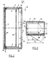
- la figure 2 montre de façon schématique, vu de face, un premier mode d'assemblage dit "décentré" des caches et du cadre du châssis pivotant, monté dans l'armature de l'armoire,
- la figure 3 est une vue par dessus faite selon la flèche III de la figure 2,
- la figure 4 est une vue en perspective, éclatée, du second mode d'assemblage dit "centré" des caches et du cadre du châssis pivotant,
- la figure 5 montre une vue du dessus de la figure 4 faite selon la flèche V de cette figure,
- la figure 6 montre de façon schématique, en vue de face, les pièces du châssis pivotant assemblées selon le mode "centré", le châssis pivotant étant monté dans l'armature de l'armoire,
- la figure 7 est une vue du dessus faite selon la flèche VII de la figure 6.
Claims (7)
- Châssis pivotant d'armoire destinée à recevoir un appareillage notamment électrique ou électronique, du type formé d'un cadre rectangulaire (7) comprenant deux traverses horizontales (9) et deux montants verticaux (8) et d'au moins un cache (14), caractérisé en ce que le premier montant vertical (8a) est fixé aux traverses à l'une de leurs extrémités libres (9a) et le second montant vertical (8b) s'étend entre les traverses et est écarté d'une distance déterminée de leurs extrémités libres opposées (9b), définissant une surface ouverte entre lesdites extrémités libres opposées des traverses et ledit second montant; et que le châssis comprend de plus un premier cache (14a), de hauteur réduite, égale à celle du second montant vertical (8b), et un second cache (14b) ; le premier cache (14a) de hauteur réduite comprend des premiers moyens (37) de fixation, coopérant avec des moyens (82) de fixation du second montant vertical (8b), pour s'assembler avec ce second montant en occupant ainsi ladite surface ouverte, et des seconds moyens (27) de fixation au second cache (14b) ; le second cache (14b) comprend des premiers moyens (47) de fixation, coopérant avec des moyens (84) de fixation du premier montant vertical (8a) et des seconds moyens (57) de fixation coopérant avec lesdits seconds moyens (27) du premier cache (14a), ce second cache (14b) pouvant s'assembler au premier cache (14a) ou au premier montant vertical (8a).
- Châssis pivotant d'armoire selon la revendication 1, caractérisé en ce que chaque cache (14a, 14b), y compris ses moyens de fixation précités (27, 37 ; 47, 57) est symétrique par rapport à un plan médian vertical (60 ; 61).
- Châssis pivotant d'armoire selon l'une quelconque des revendications 1 à 2, caractérisé en ce que le premier montant (8a) a une hauteur égale à celle du second montant (8b) et s'étend entre les traverses (9).
- Châssis pivotant d'armoire selon l'une quelconque des revendications 1 à 3, caractérisé en ce que le second cache (14b) a une hauteur égale à celle du cadre (7).
- Châssis pivotant d'armoire selon l'une quelconque des revendications 1 à 4, caractérisé en ce que chaque traverse (9) comprend en symétrie, à chacune de ses extrémités libres, des moyens de fixation en articulation à l'armoire.
- Châssis pivotant d'armoire selon l'une quelconque des revendications 1 à 5, caractérisé en ce que le premier et le second cache ont une largeur sensiblement égale.
- Armoire comportant un châssis pivotant d'armoire défini selon l'une quelconque des revendications 1 à 6.
Applications Claiming Priority (2)
| Application Number | Priority Date | Filing Date | Title |
|---|---|---|---|
| FR9307405 | 1993-06-18 | ||
| FR9307405A FR2706694B1 (fr) | 1993-06-18 | 1993-06-18 | Châssis pivotant d'armoire électrique et armoire comportant un tel chassis pivotant. |
Publications (2)
| Publication Number | Publication Date |
|---|---|
| EP0630088A1 EP0630088A1 (fr) | 1994-12-21 |
| EP0630088B1 true EP0630088B1 (fr) | 1998-08-26 |
Family
ID=9448304
Family Applications (1)
| Application Number | Title | Priority Date | Filing Date |
|---|---|---|---|
| EP19940410042 Expired - Lifetime EP0630088B1 (fr) | 1993-06-18 | 1994-06-08 | Châssis pivotant d'armoire électrique et armoire comportant un tel châssis pivotant |
Country Status (4)
| Country | Link |
|---|---|
| EP (1) | EP0630088B1 (fr) |
| DE (1) | DE69412712T2 (fr) |
| ES (1) | ES2122198T3 (fr) |
| FR (1) | FR2706694B1 (fr) |
Families Citing this family (4)
| Publication number | Priority date | Publication date | Assignee | Title |
|---|---|---|---|---|
| DE19506744C1 (de) * | 1995-02-27 | 1996-04-18 | Loh Kg Rittal Werk | Schaltschrank mit Rahmengestell und Türelementen |
| DE19647726C2 (de) * | 1996-11-19 | 1999-11-04 | Loh Kg Rittal Werk | Schaltschrank |
| DE19737425A1 (de) * | 1997-08-21 | 1999-03-04 | Siemens Ag | Schaltschrank mit einem Schwenkrahmen |
| DE102007039881A1 (de) | 2007-08-20 | 2009-02-26 | Siemens Ag | Schwenkrahmen für eine Stromverteilereinheit |
Family Cites Families (2)
| Publication number | Priority date | Publication date | Assignee | Title |
|---|---|---|---|---|
| EP0338341A3 (fr) * | 1988-04-19 | 1989-12-20 | Rittal-Werk Rudolf Loh GmbH & Co. KG | Armoire de commutation à cadre pivotant |
| DE3917985A1 (de) * | 1988-06-09 | 1989-12-14 | Schaefer Gmbh Fritz | Schaltschrank |
-
1993
- 1993-06-18 FR FR9307405A patent/FR2706694B1/fr not_active Expired - Fee Related
-
1994
- 1994-06-08 DE DE1994612712 patent/DE69412712T2/de not_active Expired - Fee Related
- 1994-06-08 ES ES94410042T patent/ES2122198T3/es not_active Expired - Lifetime
- 1994-06-08 EP EP19940410042 patent/EP0630088B1/fr not_active Expired - Lifetime
Also Published As
| Publication number | Publication date |
|---|---|
| FR2706694B1 (fr) | 1995-08-04 |
| DE69412712T2 (de) | 1999-03-04 |
| DE69412712D1 (de) | 1998-10-01 |
| FR2706694A1 (fr) | 1994-12-23 |
| ES2122198T3 (es) | 1998-12-16 |
| EP0630088A1 (fr) | 1994-12-21 |
Similar Documents
| Publication | Publication Date | Title |
|---|---|---|
| EP0013318B1 (fr) | Terminal d'entrée de données à configuration modifiable | |
| EP0402456B1 (fr) | Terminal informatique portatif a ecran pivotant | |
| FR2526286A1 (fr) | Dispositif pour armoire munie d'une porte pouvant s'ouvrir vers l'exterieur en pivotant autour de l'un ou l'autre de deux bords opposes | |
| EP0084510A1 (fr) | Regard circulaire de chaussée à demi-tampons articulés | |
| EP1116075A1 (fr) | Montre-bracelet reversible | |
| CH672662A5 (fr) | ||
| EP0545223A1 (fr) | Bâti d'équipements électroniques, notamment de télécommunications | |
| EP0630088A1 (fr) | Châssis pivotant d'armoire électrique et armoire comportant un tel châssis pivotant | |
| FR2501959A1 (fr) | Tondeuse a gazon rotative comportant a l'arriere un montage protege-pieds | |
| FR2542683A1 (fr) | Agencement de tableau de bord pour vehicule automobile et vehicule ainsi equipe | |
| EP1238327B1 (fr) | Dispositif d'affichage d'image et cadre pour un tel dispositif | |
| EP0684672A1 (fr) | Coffret notamment pour appareillage électrique basse tension | |
| EP0192520B1 (fr) | Dispositif pour le montage d'une porte de coffret permettant des angles d'ouverture différents, et coffret équipé d'un tel dispositif | |
| EP0798953B1 (fr) | Armoire électrique extensible, et à socle intégré | |
| EP0921617B1 (fr) | Support pour appareillage à disposer le long d'une goulotte | |
| EP0263018B1 (fr) | Assemblage de porte sur coffret électrique et éléments constitutifs | |
| EP0192519B1 (fr) | Dispositif de montage d'une platine support dans un coffret de distribution | |
| FR2692098A1 (fr) | Appareil électronique transformable pour montage mural ou en baie. | |
| EP4345857B1 (fr) | Face avant pour un appareillage électrique de protection et appareil électrique de protection | |
| BE1013053A3 (fr) | Boite d'encastrement susceptible d'etre jumelee avec un autre, notamment pour appareillage electrique. | |
| FR2700644A1 (fr) | Armoire électrique ou électronique à cadre pivotant. | |
| EP1396603B1 (fr) | Vantail pour porte sectionnelle et porte comprenant un tel vantail | |
| FR2849168A1 (fr) | Support de broche, equipement comprenant un tel support et four electromenager comprenant un tel equipement. | |
| FR2774504A1 (fr) | Capot a volet monte pivotant, notamment pour platine de disjoncteur | |
| CH691015A5 (fr) | Cadre pour appareillage électrique. |
Legal Events
| Date | Code | Title | Description |
|---|---|---|---|
| PUAI | Public reference made under article 153(3) epc to a published international application that has entered the european phase |
Free format text: ORIGINAL CODE: 0009012 |
|
| AK | Designated contracting states |
Kind code of ref document: A1 Designated state(s): BE DE ES GB |
|
| 17P | Request for examination filed |
Effective date: 19950511 |
|
| 17Q | First examination report despatched |
Effective date: 19961017 |
|
| GRAG | Despatch of communication of intention to grant |
Free format text: ORIGINAL CODE: EPIDOS AGRA |
|
| GRAG | Despatch of communication of intention to grant |
Free format text: ORIGINAL CODE: EPIDOS AGRA |
|
| GRAH | Despatch of communication of intention to grant a patent |
Free format text: ORIGINAL CODE: EPIDOS IGRA |
|
| GRAH | Despatch of communication of intention to grant a patent |
Free format text: ORIGINAL CODE: EPIDOS IGRA |
|
| GRAA | (expected) grant |
Free format text: ORIGINAL CODE: 0009210 |
|
| AK | Designated contracting states |
Kind code of ref document: B1 Designated state(s): BE DE ES GB |
|
| REF | Corresponds to: |
Ref document number: 69412712 Country of ref document: DE Date of ref document: 19981001 |
|
| GBT | Gb: translation of ep patent filed (gb section 77(6)(a)/1977) |
Effective date: 19981001 |
|
| REG | Reference to a national code |
Ref country code: ES Ref legal event code: FG2A Ref document number: 2122198 Country of ref document: ES Kind code of ref document: T3 |
|
| PGFP | Annual fee paid to national office [announced via postgrant information from national office to epo] |
Ref country code: GB Payment date: 19990602 Year of fee payment: 6 |
|
| PGFP | Annual fee paid to national office [announced via postgrant information from national office to epo] |
Ref country code: ES Payment date: 19990621 Year of fee payment: 6 |
|
| PLBE | No opposition filed within time limit |
Free format text: ORIGINAL CODE: 0009261 |
|
| STAA | Information on the status of an ep patent application or granted ep patent |
Free format text: STATUS: NO OPPOSITION FILED WITHIN TIME LIMIT |
|
| 26N | No opposition filed | ||
| PGFP | Annual fee paid to national office [announced via postgrant information from national office to epo] |
Ref country code: BE Payment date: 19990819 Year of fee payment: 6 |
|
| PG25 | Lapsed in a contracting state [announced via postgrant information from national office to epo] |
Ref country code: GB Free format text: LAPSE BECAUSE OF NON-PAYMENT OF DUE FEES Effective date: 20000608 |
|
| PG25 | Lapsed in a contracting state [announced via postgrant information from national office to epo] |
Ref country code: ES Free format text: THE PATENT HAS BEEN ANNULLED BY A DECISION OF A NATIONAL AUTHORITY Effective date: 20000609 |
|
| PG25 | Lapsed in a contracting state [announced via postgrant information from national office to epo] |
Ref country code: BE Free format text: LAPSE BECAUSE OF NON-PAYMENT OF DUE FEES Effective date: 20000630 |
|
| BERE | Be: lapsed |
Owner name: S.A. SCHNEIDER ELECTRIC Effective date: 20000630 |
|
| GBPC | Gb: european patent ceased through non-payment of renewal fee |
Effective date: 20000608 |
|
| REG | Reference to a national code |
Ref country code: ES Ref legal event code: FD2A Effective date: 20020304 |
|
| PGFP | Annual fee paid to national office [announced via postgrant information from national office to epo] |
Ref country code: DE Payment date: 20080613 Year of fee payment: 15 |
|
| PG25 | Lapsed in a contracting state [announced via postgrant information from national office to epo] |
Ref country code: DE Free format text: LAPSE BECAUSE OF NON-PAYMENT OF DUE FEES Effective date: 20100101 |