EP0629806B1 - Raccord pour conduits pour fluides frigorigènes - Google Patents
Raccord pour conduits pour fluides frigorigènes Download PDFInfo
- Publication number
- EP0629806B1 EP0629806B1 EP94107810A EP94107810A EP0629806B1 EP 0629806 B1 EP0629806 B1 EP 0629806B1 EP 94107810 A EP94107810 A EP 94107810A EP 94107810 A EP94107810 A EP 94107810A EP 0629806 B1 EP0629806 B1 EP 0629806B1
- Authority
- EP
- European Patent Office
- Prior art keywords
- locking
- ring
- accordance
- refrigerant
- plug
- Prior art date
- Legal status (The legal status is an assumption and is not a legal conclusion. Google has not performed a legal analysis and makes no representation as to the accuracy of the status listed.)
- Expired - Lifetime
Links
Images


Classifications
-
- B—PERFORMING OPERATIONS; TRANSPORTING
- B60—VEHICLES IN GENERAL
- B60H—ARRANGEMENTS OF HEATING, COOLING, VENTILATING OR OTHER AIR-TREATING DEVICES SPECIALLY ADAPTED FOR PASSENGER OR GOODS SPACES OF VEHICLES
- B60H1/00—Heating, cooling or ventilating [HVAC] devices
- B60H1/00507—Details, e.g. mounting arrangements, desaeration devices
- B60H1/00557—Details of ducts or cables
- B60H1/00571—Details of ducts or cables of liquid ducts, e.g. for coolant liquids or refrigerants
-
- F—MECHANICAL ENGINEERING; LIGHTING; HEATING; WEAPONS; BLASTING
- F01—MACHINES OR ENGINES IN GENERAL; ENGINE PLANTS IN GENERAL; STEAM ENGINES
- F01P—COOLING OF MACHINES OR ENGINES IN GENERAL; COOLING OF INTERNAL-COMBUSTION ENGINES
- F01P11/00—Component parts, details, or accessories not provided for in, or of interest apart from, groups F01P1/00 - F01P9/00
- F01P11/04—Arrangements of liquid pipes or hoses
-
- F—MECHANICAL ENGINEERING; LIGHTING; HEATING; WEAPONS; BLASTING
- F16—ENGINEERING ELEMENTS AND UNITS; GENERAL MEASURES FOR PRODUCING AND MAINTAINING EFFECTIVE FUNCTIONING OF MACHINES OR INSTALLATIONS; THERMAL INSULATION IN GENERAL
- F16L—PIPES; JOINTS OR FITTINGS FOR PIPES; SUPPORTS FOR PIPES, CABLES OR PROTECTIVE TUBING; MEANS FOR THERMAL INSULATION IN GENERAL
- F16L37/00—Couplings of the quick-acting type
- F16L37/08—Couplings of the quick-acting type in which the connection between abutting or axially overlapping ends is maintained by locking members
- F16L37/084—Couplings of the quick-acting type in which the connection between abutting or axially overlapping ends is maintained by locking members combined with automatic locking
- F16L37/086—Couplings of the quick-acting type in which the connection between abutting or axially overlapping ends is maintained by locking members combined with automatic locking by means of latching members pushed radially by spring-like elements
-
- F—MECHANICAL ENGINEERING; LIGHTING; HEATING; WEAPONS; BLASTING
- F16—ENGINEERING ELEMENTS AND UNITS; GENERAL MEASURES FOR PRODUCING AND MAINTAINING EFFECTIVE FUNCTIONING OF MACHINES OR INSTALLATIONS; THERMAL INSULATION IN GENERAL
- F16L—PIPES; JOINTS OR FITTINGS FOR PIPES; SUPPORTS FOR PIPES, CABLES OR PROTECTIVE TUBING; MEANS FOR THERMAL INSULATION IN GENERAL
- F16L37/00—Couplings of the quick-acting type
- F16L37/08—Couplings of the quick-acting type in which the connection between abutting or axially overlapping ends is maintained by locking members
- F16L37/084—Couplings of the quick-acting type in which the connection between abutting or axially overlapping ends is maintained by locking members combined with automatic locking
- F16L37/088—Couplings of the quick-acting type in which the connection between abutting or axially overlapping ends is maintained by locking members combined with automatic locking by means of a split elastic ring
- F16L37/0885—Couplings of the quick-acting type in which the connection between abutting or axially overlapping ends is maintained by locking members combined with automatic locking by means of a split elastic ring with access to the split elastic ring from a radial or tangential opening in the coupling
-
- F—MECHANICAL ENGINEERING; LIGHTING; HEATING; WEAPONS; BLASTING
- F16—ENGINEERING ELEMENTS AND UNITS; GENERAL MEASURES FOR PRODUCING AND MAINTAINING EFFECTIVE FUNCTIONING OF MACHINES OR INSTALLATIONS; THERMAL INSULATION IN GENERAL
- F16L—PIPES; JOINTS OR FITTINGS FOR PIPES; SUPPORTS FOR PIPES, CABLES OR PROTECTIVE TUBING; MEANS FOR THERMAL INSULATION IN GENERAL
- F16L37/00—Couplings of the quick-acting type
- F16L37/08—Couplings of the quick-acting type in which the connection between abutting or axially overlapping ends is maintained by locking members
- F16L37/084—Couplings of the quick-acting type in which the connection between abutting or axially overlapping ends is maintained by locking members combined with automatic locking
- F16L37/098—Couplings of the quick-acting type in which the connection between abutting or axially overlapping ends is maintained by locking members combined with automatic locking by means of flexible hooks
- F16L37/0982—Couplings of the quick-acting type in which the connection between abutting or axially overlapping ends is maintained by locking members combined with automatic locking by means of flexible hooks with a separate member for releasing the coupling
-
- F—MECHANICAL ENGINEERING; LIGHTING; HEATING; WEAPONS; BLASTING
- F16—ENGINEERING ELEMENTS AND UNITS; GENERAL MEASURES FOR PRODUCING AND MAINTAINING EFFECTIVE FUNCTIONING OF MACHINES OR INSTALLATIONS; THERMAL INSULATION IN GENERAL
- F16L—PIPES; JOINTS OR FITTINGS FOR PIPES; SUPPORTS FOR PIPES, CABLES OR PROTECTIVE TUBING; MEANS FOR THERMAL INSULATION IN GENERAL
- F16L37/00—Couplings of the quick-acting type
- F16L37/08—Couplings of the quick-acting type in which the connection between abutting or axially overlapping ends is maintained by locking members
- F16L37/12—Couplings of the quick-acting type in which the connection between abutting or axially overlapping ends is maintained by locking members using hooks, pawls or other movable or insertable locking members
- F16L37/14—Joints secured by inserting between mating surfaces an element, e.g. a piece of wire, a pin, a chain
- F16L37/142—Joints secured by inserting between mating surfaces an element, e.g. a piece of wire, a pin, a chain where the securing element is inserted tangentially
- F16L37/144—Joints secured by inserting between mating surfaces an element, e.g. a piece of wire, a pin, a chain where the securing element is inserted tangentially the securing element being U-shaped
-
- F—MECHANICAL ENGINEERING; LIGHTING; HEATING; WEAPONS; BLASTING
- F25—REFRIGERATION OR COOLING; COMBINED HEATING AND REFRIGERATION SYSTEMS; HEAT PUMP SYSTEMS; MANUFACTURE OR STORAGE OF ICE; LIQUEFACTION SOLIDIFICATION OF GASES
- F25B—REFRIGERATION MACHINES, PLANTS OR SYSTEMS; COMBINED HEATING AND REFRIGERATION SYSTEMS; HEAT PUMP SYSTEMS
- F25B41/00—Fluid-circulation arrangements
- F25B41/40—Fluid line arrangements
Definitions
- the invention relates to a refrigerant coupling for connecting refrigerant lines, in particular for use in motor vehicles, with two pipe connections which can be plugged into one another as a plug on the one hand and as a sleeve on the other and can be sealed against one another by means of at least one sealing element and can be axially secured in a nested position by means of a closure arrangement.
- a refrigerant coupling for air conditioning systems of motor vehicles which is provided with a plug connection.
- one pipe connection is provided with a receptacle serving as a sleeve, which has a widened end region.
- the other pipe connection is provided with a plug-in connector which serves as a plug and can be inserted with a precise fit into the receiving connector.
- the inner wall of the receptacle and the outer circumference of the push-in fitting lie against each other.
- circumferential sealing rings are provided between them.
- Closure arrangement provided in the form of a clamping ring which is supported by a spiral spring acting in the circumferential direction.
- An axially compressible element which can be axially compressed by the clamping ring and which is arranged between flanges of the plug-in connector and the receiving connector protruding radially outwards serves as an anti-rotation device for the pipe connections.
- a quick coupling for connecting pipes in which a serving as a connector, provided with a conically widened area pipe connection can be inserted into the other, serving as a sleeve and provided with a widened area pipe connection.
- the connection between the two pipe connections is sealed by an elastic sealing ring which is arranged radially between the conically widening region of the plug and the widened region of the sleeve and extends axially over almost the entire length of the conically widened region of the plug.
- a locking ring axially engaging behind a stop collar of the plug is provided.
- a quick coupling for connecting refrigerant lines for use in motor vehicles in which the two pipe connections of the refrigerant lines are designed as plugs or sleeves and can be axially inserted into one another.
- the plug is provided with a flared collar.
- the sleeve is cylindrically expanded compared to the diameter of the plug.
- the plug and the sleeve are inserted into each other with the interposition of a spacer, an elastic sealing ring and a socket at a radial distance.
- the socket and the spacer serve to guide and support the plug in the sleeve for stabilizing the connection between the two refrigerant lines, the sealing ring serves to seal the connection of the two Pipe connections.
- the bushing and the spacer like the sealing ring consisting of an elastomer, are made of electrically non-conductive material.
- the object of the invention is to provide a refrigerant coupling of the type mentioned which, with simple and reliable assembly using simple means, ensures a secure sealing effect and a stable connection between the refrigerant lines.
- the socket is dimensionally stable and extends over the entire length of the annular space between the plug and the socket, that the socket with its outer circumference is non-positively and tightly fit into a receiving area of the socket, and that the socket on its inner circumference is provided with at least two circumferential sealing elements arranged axially offset from one another for the tight and non-positive encapsulation of the plug.
- sealing rings designed as O-rings, circumferential sealing lips and sealing webs are provided as sealing elements.
- the combination element serves to seal the connection between the refrigerant lines, the centering of the plug in the sleeve achieving a uniform sealing effect over the entire circumference.
- the integration of sealing elements in the combination element means that the sealing elements are connected to the combination element as separate parts by inserting or inserting them into corresponding recesses or annular grooves of the combination element with this in a form-fitting and / or non-positive manner or already integrally formed on it during the production of the combination element be, in particular by spraying or the like. Because the non-conductive combination element holds the plug in the socket without touching it, corrosion with metallic pipe connections is effectively avoided.
- the combination element also a support function for the coupling, since it essentially fills the annular space in a form-fitting manner via the plug-in length of the plug and sleeve.
- This support effect results in a compact and stable connection between the two refrigerant lines, as a result of which loads can also be absorbed by the refrigerant coupling while a motor vehicle is in motion, without the positioning of the plug and sleeve changing relative to one another, which could result in a deteriorated sealing effect.
- the solution according to the invention achieves simple and quick assembly with high accuracy and stability of the connection created.
- the refrigerant clutch according to the invention is therefore particularly suitable for air conditioning systems in the engine compartment of motor vehicles, in which relatively high loads are exerted on the refrigerant clutch during driving operation.
- the annular combination element is made of plastic, can be fitted on its outer circumference in a force-fitting and tight manner into a receiving area of the sleeve, and is provided on its inner circumference with at least two circumferential sealing elements arranged axially offset from one another.
- the non-positive and tight fit in the receiving area of the sleeve takes place in various embodiments according to the invention either by gluing, by pressing or by inserting in connection with the provision of circumferential sealing rings or sealing lips on the outer circumference of the combination element, which ensure a tight and non-positive fit in the sleeve.
- the locking arrangement is provided with a locking ring held axially positively on the sleeve, in which a radially expandable for axially inserting and removing the plug and the plug in the sleeve in the inserted position axially positively locking locking clip is captively integrated.
- the closure clip is designed as a spring with a closed cross-section, surrounding the plug in the assembled state, which is supported on an inner wall of the lock ring and has at least one engagement element accessible from an outside of the lock ring for releasing the closure clip.
- the locking clip is thus held captively in the locking ring both in the assembled and disassembled state of the locking ring and from its position axially engaging behind the plug in a simple manner from the outside of the locking ring by the attack of a hand or a tool on the respective engagement element expandable that the connector is released in the axial direction.
- two engagement pins are on two opposite sides of the spring as engagement elements provided that protrude radially outward through the wall of the locking ring.
- the engagement pins are pressed radially inwards in a simple manner from the two opposite sides of the locking ring, as a result of which the connection between the two pipe connections is released.
- a half-shell-shaped dismantling tool is provided, which can be placed on the locking ring and is provided with two cams projecting radially inwards at the level of the engagement pins for releasing the spring.
- the two cams press into the opening of the locking ring for the engagement pins, whereby the engagement pins are pressed inwards.
- the dismantling tool is provided with a collar-like catch edge for positive axial securing of the plug during dismantling, which projects radially inward beyond the radial height of the plug collar and is arranged at an axial distance from the plug collar in the mounted state.
- Refrigerant lines are under high pressure during operation.
- the catch edge is provided, which catches the plug and holds it in a relaxed position relative to the sleeve .
- the axial distance is less than the axial length of the combination element. This ensures that the connector is still positioned in the area of the sleeve after loosening.
- the two half-shells can be pivotally connected to one another by means of a hinge connection and can be connected to one another in a ring on the opposite side by means of a latching connection.
- the two half-shells can be guided over the sleeve in the opened state and pressed together so that they overlap the sleeve. Disassembly is carried out in the opposite way.
- the hinge connection has at least two latching elements which can be positively latched against one another and pivoted relative to one another and which are respectively arranged on one and the other half-shell. This creates a hinge clip connection that is easy to manufacture and allows quick assembly and disassembly.
- the locking clip is designed as a substantially U-shaped, elastically expandable bracket.
- the locking clip is held in the locking ring in the assembled state in a radial plane to a central longitudinal axis of the refrigerant coupling radially expandable, the amount of the expandability corresponds at least to the maximum diameter of the plug.
- a correspondingly conically expanded section of the plug pushes the locking clip apart until it jumps in again behind the collar of this expanded section and axially secures the plug. This enables one-handed operation during assembly, i.e. the refrigerant coupling can be plugged together using a robot assembly.
- the U-shaped bracket is provided with a shape which serves as an engagement surface for a tool. Using a suitable tool, the Locking clip can therefore be removed with a quick movement.
- the locking clip is kept sunk in the locking ring and the free ends of the U-shaped bracket of the locking clip are accessible through two openings in the locking ring by means of a tool. This prevents unauthorized loosening of the locking clip, since it can only be accessed and removed using a tool.
- the closure arrangement for a connection of the plug and the sleeve in a defined position has a positive locking device against rotation.
- correspondingly interlocking pins and grooves are provided on the locking ring and on the associated collar of the plug or sleeve.
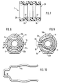
- a refrigerant coupling in the form of a quick coupling according to FIG. 1 for connecting two tubes (1, 2) serving as refrigerant lines is provided for connecting refrigerant lines of an air conditioning system of a motor vehicle.
- the pipe (1) has a socket-like pipe connection made of metal, which is designed as a plug (3) for the quick coupling serving as a refrigerant coupling.
- the plug (3) has a cylindrical tube section (13) on its free end, to which a conically widening insertion collar (8) adjoins the tube (1) in the axial direction.
- the insertion collar (8) is continued towards the pipeline (1) with the formation of a radially inwardly directed end edge (14) in a cylindrical section, which is not described in more detail.
- This cylindrical section is followed by a radially outwardly protruding protective collar (11), the functions of which will be described in more detail below.
- the metallic pipe connection is tightly connected in a manner known per se to a hose of the pipeline (1).
- the opposite refrigerant line (2) has at its end a likewise pipe-shaped, metallic pipe connection, which is designed as a sleeve (4).
- the sleeve (4) has a bell-like receiving area with a cylindrical inner wall, which axially engages over the plug (3) in the assembled state of the refrigerant coupling according to FIG. 1, but is spaced radially from the latter.
- the sleeve (4) according to FIG. 1 represents a turned part in which the bell-like receiving area is turned out on the inside.
- the bell-like receiving area has a substantially larger inner diameter than the area adjoining the refrigerant line (2).
- the inside diameter of the plug (3) corresponds to the inside diameter of the cylindrical region of the sleeve (4) which adjoins the refrigerant line (2).
- the free end of the bell-like receiving area of the sleeve (4) is formed by a radially outwardly projecting collar (10).
- the axial length of the receiving area of the sleeve (4) corresponds to the axial length of the cylindrical tube section (13) and the adjoining insertion collar (8) up to the end edge (14) of the plug (3).
- the inside diameter of the receiving area of the sleeve (4) is slightly larger than the largest outside diameter of the insert collar (8).
- the combination ring (7) is made of a non-conductive material, in the exemplary embodiment of a polyamide plastic.
- the combination ring (7) represents a rotationally symmetrical element and is provided with a cylindrical outer wall.
- the combination ring (7) essentially has a cylindrical inner wall, which is provided only in the region of one end with a conically enlarged section (28), the slope and length of which are adapted to the conical section of the insertion collar (8) of the plug (3) is.
- the inside diameter of the cylindrical inner wall is matched to the outside diameter of the cylindrical tube section (13) of the plug (3).
- the outer diameter of the outer wall of the combination ring (7) is correspondingly adapted to the bell-like receiving area of the sleeve (4).
- the combination ring (7) has two annular, axially offset external grooves (26) and two annular, also axially offset internal grooves (27), both external grooves (26) and Inner grooves (27) are designed as ring grooves with the same cross section.
- the outer grooves (26) are also offset from the inner grooves (27), whereby the thickness of the combination ring (7) could be kept less than twice the radial depth of the outer or inner grooves (26, 27).
- the combination ring (7) has a relatively stiff material so that it has good stability.
- the combination ring (7) On the end face opposite the conical section (28), the combination ring (7) has an end edge (29) which, when the combination ring (7) is in the assembled state, is pressed against the stop edge (9) of the sleeve (4). In this position, the combination ring (7) is held by the two elastically compressed sealing rings (12c and 12d) on the one hand in the receiving area of the sleeve (4) in a force-fitting and tight manner.
- the inwardly projecting sealing rings (12a and 12b) clamp and seal the cylindrical tube section (13) of the plug (3).
- the arrangement of the inner grooves (27) and the sealing rings (12a, 12b) at an axial distance from one another ensures good tolerance compensation with little radial misalignment or when the plug (3) is tilted in the sleeve (4), which is also the case in this case a secure sealing effect is guaranteed.
- the plug (3) is pushed into the combination ring (7) until the conical section of the insert collar (8) comes into contact with the conical section (28) of the combination ring (7).
- the combination ring (7) according to FIGS. 1, 4 and 7 fulfills several functions within the quick coupling. For one, centered he the plug (3) so radially in the sleeve (4) that the plug-in collar (8) has the same radial distance from the inside wall of the receiving area of the sleeve (4) and so there is no contact corrosion between the metallic materials of the connector (3) and the sleeve (4) can occur. Since the combination ring (7) almost completely fills the free annular space between the sleeve (4) and the plug (3) and has sufficient stability, it offers stable support for the plug (3) in the sleeve (4), so that the nested position caused during assembly can be reliably and precisely maintained, even when loads are placed on the refrigerant coupling.
- the combination ring (7) also makes a significant contribution to the fact that the plug (3) can be positioned so precisely in the sleeve (4) that the end edge (14) is radially aligned with the front edge of the collar (10), but that on the other hand, the free end of the plug (3) does not come into contact with the stop edge (9) of the sleeve (4). Due to the sealing rings (12) integrated in the combination ring (7), the combination ring (7) also seals the connection between the plug (3) and the sleeve (4).
- a locking arrangement in the form of a locking ring (5) is provided, which is provided with a locking clip (6) in the assembled state (Fig. 2).
- Locking ring (5) and locking clip (6) are described in more detail below.
- the locking ring (5) (Fig. 3) has two half-shells (15 and 16) which are connected to one another by means of a hinge clip connection (17) so as to be pivotable about a hinge axis parallel to the longitudinal axis of the refrigerant coupling.
- a hinge element which is open to one side and is provided with a latching opening is formed on the half-shell (15).
- a corresponding locking pin is in this locking opening of a further hinge element which is molded onto the other half-shell (16).
- the two half-shells (15 and 16) have locking elements for a locking connection (18), a locking hook being formed on the half-shell (16) and a corresponding locking point on the other half-shell (15).
- the two half-shells (15 and 16) are provided on their inner circumference with grooves which are adapted to the collar (10) of the sleeve (4) and to the protective collar (11) of the plug (3).
- the locking ring (5) To mount the locking ring (5), this is simply attached to the collar (10) of the sleeve (4) in the opened state on one half, and then the second half-shell is folded onto the first, whereby the locking ring (5) closes the collar (10) encloses over its entire scope.
- the locking ring (5) is locked on the collar (10) by the latching connection (18).
- the inside diameter of the locking ring (5) is slightly larger than the outside diameter of the insertion collar (8) of the plug (3), so that the plug (3) can be easily axially inserted into the locking ring (5) even on the sleeve (4) Sleeve (4) can be inserted. Either the combination ring (7) is already positioned in the sleeve (4) or on the plug (3).
- a locking clip (6) held in the locking ring (5) is provided, the two legs of which close the end edge (14) of the insertion collar (8) of the connector (3) in a radial plane grasp the central longitudinal axis of the refrigerant coupling on opposite sides.
- an arcuate securing area is formed in both legs of the U-shaped locking clip (6) (FIG. 2), each of which corresponds to the outer contour of the cylindrical tube section (13) and to the cylindrical area of the plug (3) adjoining the end edge (14). is adjusted.
- the securing areas of the locking clip therefore engage behind the plug-in collar (8) of the plug (3) and fix it in the inserted position the connector (3) axially.
- the locking clip (6) is made of a spring wire.
- the radial insertion and holding level of the locking clip (6) in the locking ring (5) is adapted to the annular groove of the locking ring (5) such that the annular groove in the nested position of the plug (3) and sleeve (4) on the one hand axially on the collar ( 10), the closing clip (6), on the other hand, rests on the end edge (14).
- the locking ring (5) is first placed on the collar (10) of the sleeve (4) and the locking clip (6) is inserted into the locking ring (5). If the combination ring (7) is already positioned in the sleeve (4), the plug (3) is now simply inserted into the locking ring (5) and into the sleeve (4). When the plug (3) is inserted, the conical section of the insertion collar (8) presses the legs of the locking clip (6) outwards.
- the two legs of the locking clip (6) snap elastically behind the insertion collar (8) of the plug (3) and support the stop edge (14) of the plug (3) axially.
- This assembly of the plug (3) is possible in a simple manner by one-hand operation.
- the refrigerant coupling can be, for example, by means of of a robot can also be installed automatically. This also makes it possible to provide the pipe connection of the plug (3) with a pipe bend directly, which expands the design options of the refrigerant circuit.
- the locking ring (5) has an annular groove, the diameter of which is adapted to the diameter of the protective collar (11).
- the protective collar (11) therefore lies axially against the annular groove in the insertion direction, as a result of which the interior of the refrigerant coupling is closed and thus protected against contamination.
- a dismantling tool (30) for releasing the plug (3) from the sleeve (4) is placed on a refrigerant coupling similar to FIGS. 1 to 3.
- a locking ring (5) is provided for the refrigerant coupling, which essentially corresponds to the locking ring (5) of the previously described embodiment according to FIGS. 1 to 3.
- an elastically expandable locking clip is integrated captively, which is designed with a closed cross section.
- the locking clip is designed in the form of an oval spring ring (31) which bears on two opposite sides on the inner wall of an annular groove for receiving the spring ring (31) in the locking ring (5).
- the locking ring (5) is provided with a radially outward opening, into which two engagement pins (33) of the spring ring (31) protrude radially outwards.
- the oval spring ring (31) has two web-like, radially inwardly projecting locking lugs (32), which serve to axially support the end edge (14) of the plug (3) in the mounted position. If the two engagement pins (33) of the spring washer (31) are now pressed radially inwards, the securing tabs (32) are spread out elastically radially outwards due to the spring forces that occur.
- the securing tabs (32) are dimensioned such that the free cross-section between the opposite securing tabs (32) in the spread position of the spring ring (31) is larger than the cross-section of the insertion collar (8) of the plug (3), so that the plug (3 ) can be pulled axially out of the sleeve (4) and the locking ring (5).
- the dismantling tool (30) in the form of a half-shell-shaped body which is provided at the level of the two openings in the locking ring (5) with radially inwardly projecting cams (34).
- the dismantling tool (30) is elastically spreadable to a certain extent, so that when it is pushed onto the locking ring (5) by sliding the two cams (34) along the outer periphery of the locking ring (5), it is spread until the cams (34 ) engage in the openings of the locking ring (5). As a result, the engagement pins (33) are pressed inwards, as a result of which the securing tabs (32) are spread apart.
- the dismantling tool (30) has a catching device in the form of a collar-like catching edge (25), which is described in more detail below.
- the catch edge (25) is used to axially secure the connector (3) when the refrigerant lines connected by the refrigerant coupling are still under pressure during dismantling.
- the connector (3) would namely be thrown backwards under high pressure in the axial direction after releasing the spring ring (31) serving as a locking clip, as a result of which refrigerant could escape from the refrigerant circuit in an uncontrolled manner.
- the uncontrolled backwards throwing of the connector (3) can also cause damage or injuries.
- the dismantling tool (30) with the catching device represents a half-shell-shaped stable component which is provided with a retaining edge (24) at one end and with the catching edge (25) at the opposite end, both of which protrude radially inwards.
- the retaining edge (24) is part of a groove-like depression in the area of the inner wall of the dismantling tool (30) which is adapted to the outer contour of the locking ring (5).
- the axial distance (23) of the catching edge (25) from the protective collar (11) is less than the axial length of the combination ring (7) and corresponds to the distance from the front end of the plug (3) to the sealing ring (12a), so that the plug ( 3) is still positioned in the combination ring (7) after dismantling the spring ring (31), but is no longer clamped by the sealing ring (12a).
- the connector (3) cannot be removed from the sleeve (4) even after the locking clip has been released, as long as the catch edge (25) axially secures the connector (3).
- the refrigerant coupling according to FIGS. 1 to 3 and according to FIGS. 4 to 6 is provided with a form-fitting anti-rotation device, so that the plug (3) and the sleeve (4) can only be plugged into one another in a defined position.
- an axial groove (21) is provided in the collar (10) of the sleeve (4).
- a corresponding, but not specifically designated groove is also provided in the protective collar (11).
- the locking ring (5) at the level of the collar (10) has a cam (22) which engages in the assembled position in the axial groove (21).
- the locking ring (5) at the level of the protective collar (11) has a further cam which engages in the axial groove of the protective collar (11). In the assembled state, twisting of the connector (3) and sleeve (4) relative to one another is therefore not possible.
- a locking clip (6a) according to the embodiment according to FIG. 10 corresponds essentially to the U-shaped curved locking clip (6) according to FIG. 2.
- the locking clip (6a) is additionally provided with a small bulge (38) which is also bent in a U-shape and serves as an engagement surface for a tool. This makes it possible to pull the locking clip (6a) out of the locking ring (5) in a simple manner using a suitable tool, which is only possible in the embodiment according to FIG. 2 in that a fork-shaped tool is provided on the side of the openings (19). presses against the ends of the two legs of the locking clip (6).
- the bulge (38) therefore makes it easier to dismantle the locking clip (6a).
- the locking clip designed as a spring ring (31a) according to FIG. 8 is almost identical to the locking ring (31) according to FIGS. 4 to 6.
- only the engagement pins protruding into the openings of the locking ring (5) are outside the outer contour of the locking ring (5) provided heads (35) which are arranged at a radial distance from the outer contour of the locking ring (5).
- the embodiment according to FIG. 9 has a further locking clip, which is also designed as a closed spring ring (31b).
- the spring ring (31b) has a ring section in the ring groove of the locking ring (5) and two legs (32b) which serve to axially support the end edge (14) of the plug (3).
- Both legs (32b) are connected to each other at the level of an eccentric (36) which is rotatably mounted in the wall of the locking ring (5).
- the eccentric (36) is designed in the form of a rectangular square which has a length which is substantially greater than its width. If the eccentric (36) is therefore rotated by 90 °, it does not spread the legs (32b) by means of its broad side, as shown, but by means of its long side, as a result of which they release the plug (3).
Claims (15)
- Dispositif d'accouplement pour agent réfrigérant, destiné à l'assemblage de conduits d'agent réfrigérant, prévu en particulier pour être utilisé dans des véhicules automobiles et comprenant deux raccords de tuyaux conformés d'une part en embout mâle et d'autre part en embout femelle s'emboîtant et rendus étanches l'un par rapport à l'autre à l'aide d'au moins un élément d'étanchéité et qui peuvent être bloqués axialement en position emboîtée au moyen d'un système de verrouillage, dans lequel l'embout mâle est centré dans l'embout femelle par une douille en matériau non conducteur s'emboîtant dans l'embout femelle et est tenu à distance radiale par rapport à l'embout femelle, l'embout mâle comprenant un collet annulaire d'emboîtement débordant vers l'extérieur et entrant axialement en butée contre la douille afin de limiter la profondeur d'emboîtement de l'embout mâle, caractérisé en ce que la douille (7) est façonnée de manière à être indéformable et se prolonge sur la totalité de la longueur d'emboîtement de l'espace annulaire compris entre l'embout mâle (3) et l'embout femelle (4), en ce que la circonférence extérieure de la douille (7) est adaptable à force et étroitement dans une zone de logement de l'embout femelle (4) et en ce que la circonférence intérieure de la douille (7) est équipée d'au moins deux éléments circonférentiels d'étanchéité (12a, 12b) décalés axialement l'un par rapport à l'autre et destinés à enserrer l'embout mâle (3) de manière étanche et à force.
- Dispositif d'accouplement pour agent réfrigérant selon la revendication 1, caractérisé en ce que la douille (7) comporte aussi bien sur la circonférence extérieure que sur la circonférence intérieure deux gorges annulaires (26 ; 27) décalées axialement l'une par rapport à l'autre et dans lesquelles des joints élastiques d'étanchéité (12a, 12b, 12c, 12d) sont montés.
- Dispositif d'accouplement pour agent réfrigérant selon l'une des revendications précédentes, caractérisé en ce que le système de verrouillage est équipé d'un anneau de verrouillage (5) qui est tenu axialement par complémentarité de formes sur l'embout femelle (4) et dans lequel est engagée de manière imperdable une agrafe de verrouillage (6, 6a, 31, 31a, 31b) qui peut être écartée radialement pour l'introduction et l'extraction axiales de l'embout mâle (3) et qui bloque axialement par complémentarité de formes l'embout mâle (3) dans l'embout femelle (4) à la position emboîtée.
- Dispositif d'accouplement pour agent réfrigérant selon la revendication 3, caractérisé en ce que l'anneau de verrouillage (5) comprend deux demi-frettes (15, 16) se reliant de manière amovible l'une à l'autre.
- Dispositif d'accouplement pour agent réfrigérant selon la revendication 4, caractérisé en ce que l'agrafe de verrouillage (31, 31a, 31b) est conformée en anneau élastique ayant une section fermée, entourant l'embout mâle (3) à l'état monté, prenant appui contre une paroi intérieure de l'anneau de verrouillage (5) et comprenant au moins un élément d'attaque (33, 35, 36) accessible par un côté extérieur de l'anneau de verrouillage (5) pour le dégagement de l'agrafe de verrouillage (31, 31a, 31b).
- Dispositif d'accouplement pour agent réfrigérant selon la revendication 5, caractérisé en ce que l'élément d'attaque qui est prévu consiste en deux tenons d'attaque (33, 35) qui sont situés sur deux côtés opposés de l'anneau élastique (31, 31a) et qui passent radialement vers l'extérieur à travers la paroi de l'anneau de verrouillage (5).
- Dispositif d'accouplement pour agent réfrigérant selon la revendication 6, caractérisé en ce qu'un outil de démontage en forme de demi-enveloppe (30) qui est prévu peut se poser sur l'anneau de verrouillage (5) et comporte deux mentonnets (34) situés au niveau des tenons d'attaque (33) et orientés radialement vers l'intérieur pour le dégagement de l'anneau élastique (31).
- Dispositif d'accouplement pour agent réfrigérant selon la revendication 7, caractérisé en ce que l'outil de démontage (30) comporte un rebord de prise (25) en forme de collet qui est destiné à bloquer axialement l'embout mâle (3) par complémentarité de formes lors du démontage, qui se prolonge radialement vers l'intérieur jusqu'au dessus de la hauteur radiale d'une collerette (11) de protection faisant partie de l'embout mâle (3) et qui, à l'état monté, est disposé à distance axiale de la collerette de protection (11) lors du démontage.
- Dispositif d'accouplement pour agent réfrigérant selon la revendication 8, caractérisé en ce que la distance axiale séparant la collerette de protection (11) et le rebord de prise (25) est inférieure à la longueur axiale de la douille (7).
- Dispositif d'accouplement pour agent réfrigérant selon l'une des revendications précédentes, caractérisé en ce que le système de verrouillage destiné à l'assemblage de l'embout mâle (3) et de l'embout femelle (4) comporte à une position définie un arrêt (21, 22) bloquant toute rotation par complémentarité de formes.
- Dispositif d'accouplement pour agent réfrigérant selon l'une des revendications précédentes, caractérisé en ce que les deux demi-frettes (15, 16) peuvent être reliées pivotantes sur un côté au moyen d'un assemblage à charnière (17) et peuvent être raccordées en anneau sur le côté opposé au moyen d'un assemblage à encliquetage (18).
- Dispositif d'accouplement pour agent réfrigérant selon la revendication 11, caractérisé en ce que l'assemblage à charnière (17) comprend deux éléments d'encliquetage pouvant être enclenchés l'un dans l'autre par complémentarité de formes, pouvant pivoter l'un par rapport à l'autre et qui sont disposés d'une part sur l'une des demi-frettes (15, 16) et d'autre part sur l'autre.
- Dispositif d'accouplement pour agent réfrigérant selon l'une des revendications précédentes. caractérisé en ce que l'agrafe de verrouillage est conformée en étrier sensiblement en U et pouvant être écarté élastiquement.
- Dispositif d'accouplement pour agent réfrigérant selon la revendication 10, caractérisé en ce que l'étrier en U comporte une structure (38) débordant vers l'extérieur et servant de surface d'attaque pour un outil.
- Dispositif d'accouplement pour agent réfrigérant selon l'une des revendications précédentes, caractérisé en ce que l'agrafe de verrouillage (6) est tenue noyée dans l'anneau de verrouillage (5) et les extrémités libres de l'étrier en U de l'agrafe de verrouillage (6) sont accessibles au moyen d'un outil par deux trous (19) de l'anneau de verrouillage (5).
Priority Applications (1)
| Application Number | Priority Date | Filing Date | Title |
|---|---|---|---|
| US08/664,259 US5653475A (en) | 1993-06-08 | 1996-06-07 | Collant coupling for connecting coolant lines |
Applications Claiming Priority (2)
| Application Number | Priority Date | Filing Date | Title |
|---|---|---|---|
| DE4318878 | 1993-06-08 | ||
| DE4318878A DE4318878A1 (de) | 1993-06-08 | 1993-06-08 | Kältemittelkupplung zur Verbindung von Kältemittelleitungen |
Publications (3)
| Publication Number | Publication Date |
|---|---|
| EP0629806A2 EP0629806A2 (fr) | 1994-12-21 |
| EP0629806A3 EP0629806A3 (fr) | 1995-03-29 |
| EP0629806B1 true EP0629806B1 (fr) | 1997-12-29 |
Family
ID=6489804
Family Applications (1)
| Application Number | Title | Priority Date | Filing Date |
|---|---|---|---|
| EP94107810A Expired - Lifetime EP0629806B1 (fr) | 1993-06-08 | 1994-05-20 | Raccord pour conduits pour fluides frigorigènes |
Country Status (4)
| Country | Link |
|---|---|
| US (1) | US5653475A (fr) |
| EP (1) | EP0629806B1 (fr) |
| DE (2) | DE4318878A1 (fr) |
| ES (1) | ES2110652T3 (fr) |
Cited By (1)
| Publication number | Priority date | Publication date | Assignee | Title |
|---|---|---|---|---|
| CN101832440A (zh) * | 2010-05-24 | 2010-09-15 | 龚岳强 | 快速连接压缩空气输送管道的转换接头和使用方法 |
Families Citing this family (65)
| Publication number | Priority date | Publication date | Assignee | Title |
|---|---|---|---|---|
| US5647612A (en) * | 1994-04-04 | 1997-07-15 | Nippondenso Co., Ltd. | Coupling for pipes |
| DE4422116C1 (de) * | 1994-06-24 | 1995-08-31 | Ford Werke Ag | Sicherungsclip für das Aneinanderkuppeln zweier Rohre |
| AU5950796A (en) * | 1995-06-07 | 1996-12-30 | Salter Labs | Tubing end-piece and connector |
| FR2743117B1 (fr) * | 1995-12-27 | 1998-02-13 | Valeo Climatisation | Dispositif de fixation d'un motoreducteur sur une paroi dans un appareil de chauffage de vehicule |
| DE19609925A1 (de) * | 1996-03-14 | 1997-09-18 | Fichtel & Sachs Ag | Lösbare Steckverbindung |
| DE19621283B4 (de) * | 1996-05-25 | 2008-05-29 | Behr Gmbh & Co. Kg | Rohranschlußkupplung, insbesondere bei einem Wasserkasten eines Kraftfahrzeug-Wärmeübertragers |
| NL1004679C1 (nl) * | 1996-12-03 | 1998-06-05 | Applied Power Inc | Fluïduminsteekverbinding. |
| US5794988A (en) * | 1996-12-16 | 1998-08-18 | Gill; Ajit Singh | Grip coupling |
| DE19722842C2 (de) * | 1997-05-30 | 2001-04-12 | Raymond A & Cie | Lösbare Schnellkupplung |
| IT238349Y1 (it) * | 1997-07-30 | 2000-10-16 | Chemidro S A S Di Del Pin Mart | Raccordo per il collegamento di tubi mediante pressatura |
| US5964483A (en) * | 1997-11-19 | 1999-10-12 | Dayco Products, Inc. | Fluid coupling assembly, locking member therefor, and method of assembly |
| US6186560B1 (en) * | 1997-12-25 | 2001-02-13 | Ajit Singh Gill | Single bolt coupling |
| FR2775509B1 (fr) * | 1998-02-27 | 2000-08-11 | Hutchinson | Perfectionnement a un raccord encliquetable pour conduit de fluide, en particulier pour vehicule automobile |
| DE19852395C2 (de) * | 1998-05-26 | 2003-02-27 | Muhr & Bender Kg | Steckkupplung |
| US6293596B1 (en) * | 1999-01-06 | 2001-09-25 | Itt Manufacturing Enterprises, Inc. | Quick connector with after incident indicator clip |
| US7407165B1 (en) * | 2000-04-04 | 2008-08-05 | Hutchinson Fts, Inc. | Composite sleeve for sealing a tubular coupling |
| DE10029366A1 (de) * | 2000-06-15 | 2001-12-20 | Behr Gmbh & Co | Rohrkupplung, insbesondere für ein Anschlußrohr eines Wärmetauschers |
| DE10033206C1 (de) * | 2000-07-07 | 2001-08-16 | Hewing Gmbh | Rohrverbindungselement |
| SE0004701D0 (sv) | 2000-12-19 | 2000-12-19 | Siemens Elema Ab | Narkosmedelförgasare |
| US6431612B1 (en) * | 2000-12-28 | 2002-08-13 | Itt Manufacturing Enterprises, Inc. | Air flow conduit quick connector |
| US6672628B2 (en) | 2002-02-20 | 2004-01-06 | Masco Corporation Of Indiana | Quick connect hose coupling |
| EP1359361B1 (fr) * | 2002-05-04 | 2005-10-05 | TI Automotive (Fuldabrück) GmbH | Raccord pour tuyaux |
| US7011345B2 (en) * | 2002-09-27 | 2006-03-14 | The Lamson & Sessions Co. | Pipe joint and couplers |
| US20040139775A1 (en) * | 2003-01-08 | 2004-07-22 | Christopher Patterson | Method of forming double O-ring |
| US20040130148A1 (en) * | 2003-01-08 | 2004-07-08 | Christopher Patterson | Conventionally formed double O-ring coupling |
| ES2235657A1 (es) * | 2003-12-19 | 2005-07-01 | Valeo Climatizacion, S.A. | Dispositivo de conexion entre un intercambiador de calor y sus conductos de entrada y salida de fluido, en especial para aparatos de calefaccion-ventilacion y/o climatizacion de vehiculos automoviles y su correspondiente procedimiento de montaje. |
| JP4196879B2 (ja) * | 2004-05-18 | 2008-12-17 | 株式会社デンソー | 配管継手装置 |
| US7338093B2 (en) * | 2004-09-03 | 2008-03-04 | Voss Automotive Gmbh | Connection for fluid lines |
| DE102005038476B4 (de) * | 2005-08-13 | 2020-05-28 | Eaton Fluid Power Gmbh | Vorrichtung und Verfahren zum Anschluss eines Hydraulikschlauchs an einen Anschlussnippel |
| WO2007060699A1 (fr) * | 2005-11-28 | 2007-05-31 | Sit La Precisa S.P.A. | Système de branchement étanche d’un dispositif mélangeur air/gaz à une unité de vanne |
| US7784504B2 (en) * | 2006-03-06 | 2010-08-31 | Baxter International Inc. | Adapters for use with an anesthetic vaporizer |
| US8522839B2 (en) * | 2006-03-06 | 2013-09-03 | Baxter International Inc. | Adapters for use with an anesthetic vaporizer |
| DE102006010316A1 (de) | 2006-03-07 | 2007-09-13 | Karl Storz Gmbh & Co. Kg | Kupplungsmechanismus |
| WO2007127979A2 (fr) * | 2006-05-01 | 2007-11-08 | Cooper Standard Automotive, Inc. | Raccord rapide pour fluide avec support de joint intégré obtenu par moulage multi-matières |
| FR2907534B1 (fr) | 2006-10-20 | 2010-09-24 | Legris Sa | Dispositif de raccordement pour circuit de fluide de vehicule automobile |
| US7637538B2 (en) * | 2007-04-27 | 2009-12-29 | Behr America, Inc. | Heater core assembly |
| US7985068B2 (en) * | 2007-05-04 | 2011-07-26 | Irwin Industrial Tool Company | Gas appliance |
| US9144909B2 (en) * | 2007-07-05 | 2015-09-29 | Re2, Inc. | Defense related robotic systems |
| EP2065628B1 (fr) * | 2007-11-29 | 2016-03-16 | MAHLE Behr GmbH & Co. KG | Agencement avec un élément de liaison pour un accouplement tubulaire |
| US8534328B2 (en) * | 2008-04-09 | 2013-09-17 | Baxter International Inc. | Adapters for use with an anesthetic vaporizer |
| US20100283237A1 (en) * | 2009-01-24 | 2010-11-11 | Krohn Kenneth P | Device for connecting to ducts of various sizes and shapes |
| DE102009020060B4 (de) * | 2009-05-06 | 2020-12-10 | Valeo Klimasysteme Gmbh | Fahrzeugklimaanlagenbaugruppe und Verfahren zum Zusammenbau |
| CA2762766C (fr) * | 2009-05-20 | 2018-01-02 | Simon Freed | Contenant et produit pharmaceutique |
| DE102009057867A1 (de) * | 2009-12-11 | 2011-06-16 | Mahle International Gmbh | Kupplungseinrichtung und Frischluftanlage |
| DE102010037211A1 (de) | 2010-08-30 | 2012-03-01 | Contitech Kühner Gmbh & Cie. Kg | Schlauch mit niedriger Permeationsrate, insbesondere ein Hochtemperaturkälteschlauch, und Verfahren zu dessen Herstellung |
| BR112013030838A2 (pt) | 2011-06-02 | 2016-11-29 | Raymond A & Cie | conectores fabricados por impressão tridimensional |
| US8888139B2 (en) | 2011-10-04 | 2014-11-18 | American Boa Incorporated | Metal hose end fitting |
| JP6236942B2 (ja) * | 2013-07-10 | 2017-11-29 | 富士通株式会社 | 配管接続構造、冷却システム、及び、電子機器 |
| DE102013217557A1 (de) * | 2013-09-03 | 2015-03-05 | Flex-Elektrowerkzeuge Gmbh | Verbindungsvorrichtung |
| US20150167535A1 (en) * | 2013-10-15 | 2015-06-18 | Mark Jefferson Reed | Automotive engine coolant pipe repair apparatus and method |
| US20160097481A1 (en) * | 2013-10-15 | 2016-04-07 | Mark Jefferson Reed | Automotive engine coolant pipe repair apparatus and method |
| NO20140329A1 (no) * | 2014-03-13 | 2015-09-14 | Defa As | Tilkoplingselement for motorvarmer |
| DE102015111895A1 (de) * | 2015-07-22 | 2017-01-26 | Dr. Ing. H.C. F. Porsche Aktiengesellschaft | Fahrzeugkomponente und Kraftfahrzeug |
| DE102016112529A1 (de) * | 2016-07-07 | 2018-01-11 | Norma Germany Gmbh | Verbinder für eine Fluidleitung |
| ES2651907B1 (es) | 2016-07-29 | 2018-11-16 | Cikautxo, S.Coop. | Racor hembra de conector enchufable y conector enchufable |
| CN106015780B (zh) * | 2016-08-17 | 2019-01-08 | 上海酷风汽车部件有限公司 | 一种用于汽车空调系统的管路装置 |
| US10788243B2 (en) * | 2016-08-29 | 2020-09-29 | Advanced Distributor Products Llc | Refrigerant distributor for aluminum coils |
| US10794524B2 (en) * | 2016-09-06 | 2020-10-06 | Keith R. Bunn, SR. | Pipe coupling assembly |
| US10041613B1 (en) * | 2017-01-20 | 2018-08-07 | Ajit Singh Gill | Universal coupling |
| US10351179B2 (en) | 2017-08-29 | 2019-07-16 | Matt J Schulte | Dual configuration automobile floor assembly |
| US10722324B2 (en) * | 2018-01-08 | 2020-07-28 | Stoma Ventures, LLC | Adapter for a tailpiece for a dental valve |
| CN110924468A (zh) * | 2019-11-24 | 2020-03-27 | 临海伟星新型建材有限公司 | 一种快装式柔性管道给水系统 |
| US11898687B2 (en) * | 2020-08-14 | 2024-02-13 | Ford Global Technologies, Llc | Impact absorber assembly |
| US11603952B2 (en) | 2021-07-23 | 2023-03-14 | Cooper-Standard Automotive, Inc. | In-line quick connector |
| US20230288000A1 (en) * | 2022-03-08 | 2023-09-14 | CoollT Systems, Inc. | Moldable fluid couplers and related fluid connectors, systems and methods |
Family Cites Families (37)
| Publication number | Priority date | Publication date | Assignee | Title |
|---|---|---|---|---|
| GB210322A (en) * | 1923-04-04 | 1924-01-31 | John Jones | An improvement in or relating to taps or valves |
| FR909478A (fr) * | 1944-10-17 | 1946-05-09 | Raccord de tuyaux | |
| US2479711A (en) * | 1945-11-08 | 1949-08-23 | Arutunoff Armais | Cartridge type seal for rotating shafts |
| US2485976A (en) * | 1946-03-08 | 1949-10-25 | Aeroquip Corp | Hydraulic connector |
| US2661967A (en) * | 1949-11-17 | 1953-12-08 | M B G Corp | Fluid seal |
| US2590565A (en) * | 1950-06-02 | 1952-03-25 | Alden E Osborn | Pipe joint |
| GB840220A (en) * | 1957-03-06 | 1960-07-06 | Nat Res Dev | Improvements in or relating to seals for fluids |
| FR1195419A (fr) * | 1958-04-25 | 1959-11-17 | P C C | Joint pour canalisations |
| FR2291438A1 (fr) * | 1974-11-13 | 1976-06-11 | Gen Motors Corp | Raccord pour conduites |
| US3990727A (en) * | 1976-01-26 | 1976-11-09 | Stephen Franics Gallagher | Quick detachable coupler |
| US4123090A (en) * | 1976-07-19 | 1978-10-31 | Imperial-Eastman Corporation | Push-pull fitting |
| US4174124A (en) * | 1977-03-24 | 1979-11-13 | Pipeline Seal and Insulation Co. Ltd. | Pipe joints and connectors therefor |
| AT363743B (de) * | 1979-02-22 | 1981-08-25 | Durapipe Ltd | Mechanische verbindung zwischen zwei rohren |
| US4294473A (en) * | 1979-03-16 | 1981-10-13 | Ekman Engineering Ag | Device at mutually lockable first and second parts |
| US4345468A (en) * | 1980-10-07 | 1982-08-24 | Jogler, Inc. | Liquid sight monitor |
| DE3143015C3 (de) * | 1980-10-29 | 1999-04-29 | Donald Dekle Bartholomew | Drehbare Schnellkupplung |
| AU8441882A (en) * | 1981-06-04 | 1982-12-09 | Stonestreet and Hansen (Pty.) Ltd. | Joint using divided sleeve |
| FR2559941B1 (fr) * | 1984-02-16 | 1986-07-04 | Framatome Sa | Reacteur nucleaire du type sous-modere |
| DE3502424A1 (de) * | 1985-01-25 | 1986-07-31 | Aeroquip GmbH, 7570 Baden-Baden | Kaeltemittelkupplung, insbesondere fuer klimaanlagen von kraftfahrzeugen |
| US4691943A (en) * | 1985-04-24 | 1987-09-08 | Schmelzer Corporation | Quick connect fluid fitting assembly |
| US4715624A (en) * | 1985-06-24 | 1987-12-29 | Frye Henry A | Plastic to metal transition fitting |
| US4600221A (en) * | 1985-09-30 | 1986-07-15 | Bimba Charles W | Connection system for flexible tubing |
| DE3729570A1 (de) * | 1986-09-16 | 1988-03-17 | Schaefer Johannes | Steckverbindung fuer den anschluss von rohr- und schlauchleitungen, insbesondere fuer die verwendung in rohrleitungssystemen von kraftfahrzeugen |
| JPH0618123Y2 (ja) * | 1989-11-11 | 1994-05-11 | 日東工器株式会社 | 管継手のソケット |
| US4874174A (en) * | 1987-03-05 | 1989-10-17 | Aisin Seiki Kabushiki Kaisha | Tube connecting unit |
| JP2691550B2 (ja) * | 1988-03-01 | 1997-12-17 | 臼井国際産業株式会社 | 細径配管接続用コネクター |
| US4869534A (en) * | 1988-09-26 | 1989-09-26 | Huron Products Corporation | Swivelable quick connector |
| US4881760A (en) * | 1988-11-07 | 1989-11-21 | Stanley Aviation Corporation | Conduit coupling device with redundancy features |
| US4927185A (en) * | 1989-03-07 | 1990-05-22 | Huron Products Corporation | Release tool for fluid quick connectors |
| DE8904555U1 (fr) * | 1989-04-11 | 1989-06-01 | Hutchinson Gummiwarenfabrik Gmbh, 6800 Mannheim, De | |
| SU1665161A1 (ru) * | 1989-08-18 | 1991-07-23 | Предприятие П/Я Г-4213 | Быстроразъемное соединение трубопроводов |
| DE4035008C2 (de) * | 1990-02-28 | 1993-10-28 | Suttner Gmbh & Co Kg | Schlauchkupplung für Hochdruckschläuche |
| JP3031959B2 (ja) * | 1990-05-30 | 2000-04-10 | 臼井国際産業株式会社 | 配管接続用コネクター |
| FR2685434B1 (fr) * | 1991-12-18 | 1994-04-01 | Hutchinson Sa | Dispositif de raccord rapide pour la liaison etanche entre eux de deux tubes ou tuyaux rigides ou semi-rigides. |
| DE4300037C1 (de) * | 1993-01-02 | 1994-04-21 | Raymond A & Cie | Lösbare Steckverbindung |
| US5405175A (en) * | 1993-09-24 | 1995-04-11 | Siemens Automotive L.P. | Clip attachment of fuel tube to fuel rail |
| US5415825A (en) * | 1993-11-02 | 1995-05-16 | Dayco Products, Inc. | Branched hose construction, hose unit therefor and methods of making the same |
-
1993
- 1993-06-08 DE DE4318878A patent/DE4318878A1/de not_active Withdrawn
-
1994
- 1994-05-20 ES ES94107810T patent/ES2110652T3/es not_active Expired - Lifetime
- 1994-05-20 DE DE59404865T patent/DE59404865D1/de not_active Expired - Lifetime
- 1994-05-20 EP EP94107810A patent/EP0629806B1/fr not_active Expired - Lifetime
-
1996
- 1996-06-07 US US08/664,259 patent/US5653475A/en not_active Expired - Lifetime
Cited By (2)
| Publication number | Priority date | Publication date | Assignee | Title |
|---|---|---|---|---|
| CN101832440A (zh) * | 2010-05-24 | 2010-09-15 | 龚岳强 | 快速连接压缩空气输送管道的转换接头和使用方法 |
| CN101832440B (zh) * | 2010-05-24 | 2011-12-14 | 龚岳强 | 快速连接压缩空气输送管道的转换接头和使用方法 |
Also Published As
| Publication number | Publication date |
|---|---|
| EP0629806A2 (fr) | 1994-12-21 |
| EP0629806A3 (fr) | 1995-03-29 |
| DE4318878A1 (de) | 1994-12-15 |
| US5653475A (en) | 1997-08-05 |
| DE59404865D1 (de) | 1998-02-05 |
| ES2110652T3 (es) | 1998-02-16 |
Similar Documents
| Publication | Publication Date | Title |
|---|---|---|
| EP0629806B1 (fr) | Raccord pour conduits pour fluides frigorigènes | |
| EP0906534B1 (fr) | Connecteur amovible avec indicateur de montage | |
| DE3143015C2 (fr) | ||
| DE19741641C2 (de) | Anschlußvorrichtung für ein Rohr- oder Schlauchteil | |
| EP1058799B1 (fr) | Attache rapide destinee a des conduits metalliques | |
| EP0613225A1 (fr) | Entretoise pour fils conducteurs, notamment pour faisceaux de lignes électriques dans un avion | |
| EP0983462A1 (fr) | Dispositif de raccordement rapide amovible | |
| WO2005064222A1 (fr) | Raccord a emboitement pour conduites de fluide | |
| EP4127543B1 (fr) | Raccord de type enfichable ayant un verrouillage de préassemblage | |
| DE2921568A1 (de) | Steckverbindungs-anschlusstueck fuer druckluftbremsanlagen | |
| EP2487399B1 (fr) | Raccord emboîtable pour conduites de fluide | |
| EP3379129A1 (fr) | Connecteur | |
| EP2712413B1 (fr) | Dispositif de raccordement permettant de raccorder une conduite de fluides | |
| EP1567800B1 (fr) | Raccord de conduite emboitable et blocable | |
| DE202020101638U1 (de) | Steckverbinder mit Vormontagesicherung | |
| DE202007012400U1 (de) | Anschlussvorrichtung für Medienleitungen im Bereich einer Wandungsdurchführung sowie Wandungselement | |
| EP0319746B1 (fr) | Dispositif d'accouplement de deux conduites, en particulier pour des conduites de carburant | |
| EP1352193A1 (fr) | Dispositif de raccordement enfichable encliquetable | |
| WO2001061223A1 (fr) | Robinet d'arret rotatif pour embout d'enfichage avec raccord coude | |
| EP1801485B1 (fr) | Raccord multiple pour tubes ou tuyaux | |
| EP3526507B1 (fr) | Connecteur, module de connecteur et procédé permettant de produire un connecteur | |
| EP0691501B1 (fr) | Raccord à fiche pour tuyaux flexibles et/ou tuyaux rigides | |
| DE102009008609B4 (de) | Steckverbindung für Fluid-Leitungen | |
| DE102004025069B4 (de) | Vorrichtung zur Verbindung zweier Rohrabschnitte | |
| WO2022238306A1 (fr) | Système de raccordement et procédé d'assemblage d'un système de raccordement |
Legal Events
| Date | Code | Title | Description |
|---|---|---|---|
| PUAI | Public reference made under article 153(3) epc to a published international application that has entered the european phase |
Free format text: ORIGINAL CODE: 0009012 |
|
| AK | Designated contracting states |
Kind code of ref document: A2 Designated state(s): DE ES FR GB IT |
|
| PUAL | Search report despatched |
Free format text: ORIGINAL CODE: 0009013 |
|
| AK | Designated contracting states |
Kind code of ref document: A3 Designated state(s): DE ES FR GB IT |
|
| 17P | Request for examination filed |
Effective date: 19950614 |
|
| 17Q | First examination report despatched |
Effective date: 19960318 |
|
| GRAG | Despatch of communication of intention to grant |
Free format text: ORIGINAL CODE: EPIDOS AGRA |
|
| GRAG | Despatch of communication of intention to grant |
Free format text: ORIGINAL CODE: EPIDOS AGRA |
|
| GRAG | Despatch of communication of intention to grant |
Free format text: ORIGINAL CODE: EPIDOS AGRA |
|
| GRAH | Despatch of communication of intention to grant a patent |
Free format text: ORIGINAL CODE: EPIDOS IGRA |
|
| GRAH | Despatch of communication of intention to grant a patent |
Free format text: ORIGINAL CODE: EPIDOS IGRA |
|
| ITF | It: translation for a ep patent filed |
Owner name: DE DOMINICIS & MAYER S.R.L. |
|
| GRAA | (expected) grant |
Free format text: ORIGINAL CODE: 0009210 |
|
| AK | Designated contracting states |
Kind code of ref document: B1 Designated state(s): DE ES FR GB IT |
|
| GBT | Gb: translation of ep patent filed (gb section 77(6)(a)/1977) |
Effective date: 19980113 |
|
| REF | Corresponds to: |
Ref document number: 59404865 Country of ref document: DE Date of ref document: 19980205 |
|
| REG | Reference to a national code |
Ref country code: ES Ref legal event code: FG2A Ref document number: 2110652 Country of ref document: ES Kind code of ref document: T3 |
|
| ET | Fr: translation filed | ||
| PLBE | No opposition filed within time limit |
Free format text: ORIGINAL CODE: 0009261 |
|
| STAA | Information on the status of an ep patent application or granted ep patent |
Free format text: STATUS: NO OPPOSITION FILED WITHIN TIME LIMIT |
|
| 26N | No opposition filed | ||
| REG | Reference to a national code |
Ref country code: GB Ref legal event code: IF02 |
|
| PGFP | Annual fee paid to national office [announced via postgrant information from national office to epo] |
Ref country code: FR Payment date: 20100611 Year of fee payment: 17 Ref country code: ES Payment date: 20100525 Year of fee payment: 17 |
|
| PGFP | Annual fee paid to national office [announced via postgrant information from national office to epo] |
Ref country code: IT Payment date: 20100522 Year of fee payment: 17 |
|
| PGFP | Annual fee paid to national office [announced via postgrant information from national office to epo] |
Ref country code: GB Payment date: 20100519 Year of fee payment: 17 |
|
| PGFP | Annual fee paid to national office [announced via postgrant information from national office to epo] |
Ref country code: DE Payment date: 20110531 Year of fee payment: 18 |
|
| GBPC | Gb: european patent ceased through non-payment of renewal fee |
Effective date: 20110520 |
|
| REG | Reference to a national code |
Ref country code: FR Ref legal event code: ST Effective date: 20120131 |
|
| PG25 | Lapsed in a contracting state [announced via postgrant information from national office to epo] |
Ref country code: IT Free format text: LAPSE BECAUSE OF NON-PAYMENT OF DUE FEES Effective date: 20110520 |
|
| PG25 | Lapsed in a contracting state [announced via postgrant information from national office to epo] |
Ref country code: FR Free format text: LAPSE BECAUSE OF NON-PAYMENT OF DUE FEES Effective date: 20110531 |
|
| PG25 | Lapsed in a contracting state [announced via postgrant information from national office to epo] |
Ref country code: GB Free format text: LAPSE BECAUSE OF NON-PAYMENT OF DUE FEES Effective date: 20110520 |
|
| REG | Reference to a national code |
Ref country code: ES Ref legal event code: FD2A Effective date: 20120717 |
|
| PG25 | Lapsed in a contracting state [announced via postgrant information from national office to epo] |
Ref country code: ES Free format text: LAPSE BECAUSE OF NON-PAYMENT OF DUE FEES Effective date: 20110521 |
|
| REG | Reference to a national code |
Ref country code: DE Ref legal event code: R119 Ref document number: 59404865 Country of ref document: DE Effective date: 20121201 |
|
| PG25 | Lapsed in a contracting state [announced via postgrant information from national office to epo] |
Ref country code: DE Free format text: LAPSE BECAUSE OF NON-PAYMENT OF DUE FEES Effective date: 20121201 |