EP0629121B1 - Dishwasher with valve means for separating granules from dishwater - Google Patents
Dishwasher with valve means for separating granules from dishwater Download PDFInfo
- Publication number
- EP0629121B1 EP0629121B1 EP93905722A EP93905722A EP0629121B1 EP 0629121 B1 EP0629121 B1 EP 0629121B1 EP 93905722 A EP93905722 A EP 93905722A EP 93905722 A EP93905722 A EP 93905722A EP 0629121 B1 EP0629121 B1 EP 0629121B1
- Authority
- EP
- European Patent Office
- Prior art keywords
- socket
- granules
- cleaning machine
- liquid
- pump
- Prior art date
- Legal status (The legal status is an assumption and is not a legal conclusion. Google has not performed a legal analysis and makes no representation as to the accuracy of the status listed.)
- Expired - Lifetime
Links
Images

Classifications
-
- A—HUMAN NECESSITIES
- A47—FURNITURE; DOMESTIC ARTICLES OR APPLIANCES; COFFEE MILLS; SPICE MILLS; SUCTION CLEANERS IN GENERAL
- A47L—DOMESTIC WASHING OR CLEANING; SUCTION CLEANERS IN GENERAL
- A47L15/00—Washing or rinsing machines for crockery or tableware
- A47L15/0094—Washing or rinsing machines for crockery or tableware cleaning with abrasive solid particles, e.g. by blasting the crockery with liquid containing granules
-
- A—HUMAN NECESSITIES
- A47—FURNITURE; DOMESTIC ARTICLES OR APPLIANCES; COFFEE MILLS; SPICE MILLS; SUCTION CLEANERS IN GENERAL
- A47L—DOMESTIC WASHING OR CLEANING; SUCTION CLEANERS IN GENERAL
- A47L2601/00—Washing methods characterised by the use of a particular treatment
- A47L2601/18—Liquid and granule
-
- A—HUMAN NECESSITIES
- A47—FURNITURE; DOMESTIC ARTICLES OR APPLIANCES; COFFEE MILLS; SPICE MILLS; SUCTION CLEANERS IN GENERAL
- A47L—DOMESTIC WASHING OR CLEANING; SUCTION CLEANERS IN GENERAL
- A47L2601/00—Washing methods characterised by the use of a particular treatment
- A47L2601/20—Other treatments, e.g. dry cleaning
Definitions
- the invention relates to a cleaning machine operating with granules including a pump for ejecting liquid optionally with or without granules heavier than the liquid, through nozzles against goods to be cleaned in a treatment space which is connected to the suction side of the pump via a bottom outlet having a granule valve associated therewith, said valve comprising a socket open at both ends, which is guided for vertical displacement between a position in which the lower end of the socket is raised from the bottom of the treatment space and the upper end of the socket is engaged with a stationary cap provided above the socket, to allow the pump to draw liquid with granules entrained therein from the treatment space at a lower level at the lower end of the socket, and a lower position wherein the lower end of the socket engages the bottom of the treatment space to allow the pump to draw liquid only from an upper level at the upper end of the socket, the granules being collected on the bottom of the treatment space.
- EP-B1-0 195 959 describes a cleaning machine operating with granules having a granule valve which is also of the kind referred to above but wherein the risk of granules being withdrawn by the liquid to the pump when drawing from the upper level being eliminated by providing between the upper edge of the socket and the periphery of the cap a strainer, e.g. a filter cloth, which is so dense that no granules can pass therethrough.
- a strainer e.g. a filter cloth
- a grid operating as a splash attenuator and having square apertures defined by vertical plates, said grid attenuating the movement of granules collected in the water in the lower part of the treatment space functioning as a liquid tank, where turbulence is imparted to the liquid by the liquid ejected from the nozzles.
- the cleaning machine operating with granules comprises a parallelepipedic cabinet 10 having a bottom 12 sloping towards a bottom outlet 11 and having inverted pyramidic shape.
- the cabinet is made of stainless steel sheet and defines at the top thereof a treatment space for the goods to be cleaned, one or more racks for receiving said goods being provided in said treatment space as well as nozzle ramps for spraying the goods optionally with water having granules entrained therein or with water only.
- the arrangement of these components in the cleaning machine is well-known in the art and therefore has not been shown in more detail here. Moreover, it is unimportant to the invention how such components are arranged in detail.
- the granules used in the machine should be heavier than water and usually consist of small cylindrical bodies of plastics, e.g. polyamide.
- the lower part of the cabinet 10 forms a water tank for receiving water and granules ejected from the nozzles, and a circulation pump, not shown, is connected to the bottom outlet at a pipe stud 13 for drawing water, with or without granules, to be forwarded under pressure to the nozzles.
- an outlet chamber 14 is connected to the bottom outlet 11 via a strainer 15 which has apertures sufficiently small in order not to allow passage of granules, and which can be lifted from the bottom outlet from the interior of the cabinet 10, said strainer having for this purpose a handle 16.
- the outlet chamber 14 is connected to a valve controlled outlet pipe 17 which in turn is connected to a sewer.
- the bottom outlet 11 terminates at the lower end thereof at a bottom plate 18 having a central aperture, and a cylinder 19 is connected to this bottom plate by means of an outer flange 20 and a bolt connection 21.
- the cylinder is provided with an end cover 22 welded to the cylinder and having a central threaded bore 23.
- a piston 24 is axially displaceable inside the cylinder, a piston seal 25 being provided in the piston to seal between the piston and the cylinder.
- the piston is provided with a piston rod 26 connected to the piston, which extends freely upwards from the piston through a flanged ring 27 which is clamped by means of the bolt connection between the flange 20 and the bottom plate 18 and is sealed against the bottom plate by means of an O-ring 28.
- a helical compression spring 29 is arranged between the ring 27 and the piston 24 and biases the piston to the lower end position shown.
- a pressure fluid preferably tap water under pressure, can be supplied to the cylinder 19 from a pressurized water conduit (not shown) which is connected to the threaded bore 23, ventilation of the cylinder space between the piston and the ring 27 being provided by means of a ventilation opening 30 in the ring.
- a pipe 31 is welded to the ring, and the piston rod 26 extends through this pipe and projects upwards from the upper end thereof where a guide bushing 32 having a sealing ring 33 is provided.
- a piston rod extension 34 is screwed into the upper end of the piston rod 26 at a threaded pin 35, and a spacer socket 36 is clamped between the piston rod and the piston rod extension.
- This spacer socket has a number of radially projecting flanges 37 which are connected to a circular-cylindrical valve drum 38 so that said drum is displaceable up and down together with the piston rod 26.
- a number axially extending slots 39 are provided said slots being covered on the outside by a strainer grid mounted arround the valve drum, the passages through said grid being smaller than the granules so that the granules cannot pass through the strainer grid as long as they have not been worn to such dimension that they can no longer be used for the purpose thereof.
- a sealing ring 41 of an elastomer (rubber or plastics) is clamped by means of an encircling hose clamp 42 and this sealing ring has at the bottom thereof an inwardly directed flange to cover also the lower end edge of the valve drum.
- the valve drum 38 Under the bias of the compression spring 29 the valve drum 38 is kept with the sealing ring 41 in engagement with a valve seat 43 having a downwards tapering conical inside surface, and this valve seat is provided between the bottom 12 and the bottom outlet 11.
- a conical cap 44 is demountably secured to a cross beam 47 inside the cabinet 10 by means of an outside metal sheet 45 connected to said cap, and a screw device 46, and a handle 48 is provided on the metal sheet 45 in order that the cap can be lifted out when it has been disconnected from the cross beam.
- the cap 44 extends peripherally beyond the valve drum 38 which has the upper end thereof slightly above the lower edge of the cap when the sealing ring 41 under the bias of the compression spring engages the valve seat 43.
- a flange 49 is connected to the valve drum 38 projecting radially therefrom and spaced below the upper end of the valve drum, said flange being spaced below the lower edge of the cap 44 when the valve drum is engaged with the valve seat, and moreover extends radially slightly beyond the lower edge of the cap 44.
- valve drum 38 when the valve drum 38 is in the raised position the goods will be treated with liquid and granules entrained therein, which is circulated continuously by means of the pump.
- This treatment can be termed "water blasting".
- a cleaning process usually will be terminated by the goods being rinsed with water only in order that granules, if any, which adhere to the goods will be rinsed off, and such treatment with water only can also take place during the initial part of the cleaning process in order to rinse off food rests loosely adhering to the goods, before the "blasting" with granules is initiated.
- the pump shall draw water only the valve drum 38 should be in the lowered end position which is shown in FIG.
- valve drum 38 When the valve drum 38 shall land on the seat 43 it may very well happen - as has been found in practice - that two granules one located on top of the other will be clamped between the valve drum and the seat if the drum is engaged at the lower edge thereof directly against the seat. The consequence thereof will, of course, be that granules which land on the bottom 12 together with the water will be drawn by the pump and that no rinsing without granules can take place.
- the sealing ring 41 is provided and consists of a relatively soft elastomer and that the sealing ring is engaged with an internal conical surface on the seat 43 this drawback will be eliminated. It has been found that at the sealing ring such flow conditions will arise that there is no tendency of one granule being located upon the other and that individual granules which per chance will be clamped between the sealing ring and the seat will be pressed into the sealing ring so that there is nevertheless obtained a tight engagement between the sealing ring and the seat.
- valve drum 38 When the valve drum 38 is in the lower position the granules will be collected on the bottom 12 and water only will be passed to some degree through the apertures 39 via the strainer 40 when the water flow eventually will be limited by the granules being packed against the strainer, the main part of the water flowing into the valve drum 38 via the upper edge thereof and then through the bottom outlet 11 and the pipe stud 13 to the suction side of the pump. Even if the granules are heavier than water there is a risk that the granules will be withdrawn with the water flow passing under the cap 44 into the valve drum 38 over the upper edge thereof but this risk is reduced considerably by the engagement of the flange 49 on the valve drum.
- This flange forms together with the cap 44 a labyrinth seal which effectively excludes the granules from the space under the cap 44.
- the position of the flange 49 on the valve drum 38, i.e. the distance of the flange from the upper edge of the valve drum, and the radial dimension of the flange have to be determined empirically because these parameters are depending on the dimensioning of the valve drum 38, the size and weight of the granules, the shape of the cabinet 10 and the rate of the circulating water flow.
- the edge portion of the flange is angled upwards as shown in FIG. 1 so that the flange can be said to have the shape of a shallow bowl with flat bottom.
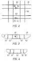
- a further development of the invention therefore comprises a splash attenuating grid 50 which is provided on the bottom 12.
- This grid is shown also in FIGS. 2 and 3. It consists of longitudinal vertical plates 51 and transverse vertical plates 52 mutually crossing at right angles and interconnected by welding at the crossing sites.
- the longitudinal plates 51 are divided midway as shown at 53 two such plates being interconnected by a plate 54 attached by welding to one part and connected by bolt connection 55 to the other part.
- the lower edge of the grid then rests against the bottom at the outer ends of the plates, which are obliquely cut at the bottom at the same angle as that formed by the bottom 12, the rest of the lower edge extending over the bottom spaced therefrom as will be seen from FIG. 1.
- the splash baffles formed by the grid attenuate the movement of the water and thus the movement of the granules collected on the bottom so that the granules will not be agitated in the water.
- the flange 49 alone is sufficient in order to achieve the purpose of the invention but in large cleaning machines operating with granules and large water flows the splash attentuating grid is an advantageous complementary device sustaining the effect aimed at by the invention.
- valve drum can be operated in another way than that disclosed herein for example electrically or mechanically but because pressurized water is available when the cleaning machine is to be used the operating device disclosed herein is preferred.
Landscapes
- Lift Valve (AREA)
- Cleaning By Liquid Or Steam (AREA)
- Washing And Drying Of Tableware (AREA)
- Glanulating (AREA)
- Extraction Or Liquid Replacement (AREA)
- Treatment Of Fiber Materials (AREA)
- Sealing Using Fluids, Sealing Without Contact, And Removal Of Oil (AREA)
- Detail Structures Of Washing Machines And Dryers (AREA)
- Check Valves (AREA)
- Magnetically Actuated Valves (AREA)
- Fluid-Driven Valves (AREA)
- Multiple-Way Valves (AREA)
Applications Claiming Priority (3)
| Application Number | Priority Date | Filing Date | Title |
|---|---|---|---|
| SE9200639A SE469923B (sv) | 1992-03-03 | 1992-03-03 | Granuldiskmaskin med ventil för separering av granuler ur vätskan |
| SE9200639 | 1992-03-03 | ||
| PCT/SE1993/000167 WO1993017610A1 (en) | 1992-03-03 | 1993-02-26 | Dishwasher with valve means for separating granules from dishwater |
Publications (2)
| Publication Number | Publication Date |
|---|---|
| EP0629121A1 EP0629121A1 (en) | 1994-12-21 |
| EP0629121B1 true EP0629121B1 (en) | 1996-04-24 |
Family
ID=20385492
Family Applications (1)
| Application Number | Title | Priority Date | Filing Date |
|---|---|---|---|
| EP93905722A Expired - Lifetime EP0629121B1 (en) | 1992-03-03 | 1993-02-26 | Dishwasher with valve means for separating granules from dishwater |
Country Status (9)
| Country | Link |
|---|---|
| US (1) | US5735730A (da) |
| EP (1) | EP0629121B1 (da) |
| AT (1) | ATE137093T1 (da) |
| DE (1) | DE69302373T2 (da) |
| DK (1) | DK0629121T3 (da) |
| FI (1) | FI105445B (da) |
| NO (1) | NO943258L (da) |
| SE (1) | SE469923B (da) |
| WO (1) | WO1993017610A1 (da) |
Families Citing this family (9)
| Publication number | Priority date | Publication date | Assignee | Title |
|---|---|---|---|---|
| SE508948C2 (sv) * | 1996-11-22 | 1998-11-16 | Viptop Ab | Blästrande diskmaskin med bräddavlopp |
| US6280301B1 (en) * | 1998-04-17 | 2001-08-28 | National Conveyor Corp. | Granule dishwashing apparatus and method of use |
| FI108995B (fi) | 1998-11-18 | 2002-05-15 | Taifun Engineering Oy Ltd | Menetelmä ja laitteisto teollisuusputkistojen puhdistamiseksi |
| SE515713C2 (sv) * | 2000-02-07 | 2001-10-01 | Gs Dev Ab | Sätt för avskiljning av fasta partiklar från vätska i en diskmaskin |
| DE102011017294A1 (de) | 2011-04-15 | 2012-10-18 | Meiko Maschinenbau Gmbh & Co. Kg | Transportspülmaschine mit Sonderbehandlungszonen |
| GB201317558D0 (en) * | 2013-10-03 | 2013-11-20 | Xeros Ltd | Cleaning apparatus |
| CN108814509B (zh) * | 2014-06-18 | 2021-03-19 | 佛山市顺德区美的洗涤电器制造有限公司 | 洗碗机 |
| SE540513C2 (en) * | 2016-03-30 | 2018-09-25 | Granuldisk Ab | Granule valve arrangement for a dishwashing apparatus |
| CN109480739A (zh) * | 2019-01-07 | 2019-03-19 | 山东格蓝科思清洗科技有限公司 | 餐具清洗机颗粒清洗机构 |
Family Cites Families (10)
| Publication number | Priority date | Publication date | Assignee | Title |
|---|---|---|---|---|
| US2621505A (en) * | 1947-12-13 | 1952-12-16 | Maytag Co | Washing machine provided with self-cleaning filter |
| US3640023A (en) * | 1969-08-19 | 1972-02-08 | Abrasive Dev | Abrading machines |
| US4184961A (en) * | 1978-02-15 | 1980-01-22 | Tecator Instrument Ab | Extraction apparatus, preferably for analyzing purposes |
| EP0016895B1 (en) * | 1979-04-02 | 1986-11-05 | Carl Göran Christer Mosell | Cleaning machine |
| SU1066790A1 (ru) * | 1982-02-18 | 1984-01-15 | Kotkov Aleksandr N | Устройство возврата дроби |
| SE454839B (sv) * | 1982-11-26 | 1988-06-06 | Adence Ab | Separationsventil till diskmaskin |
| DE3373780D1 (en) * | 1982-11-26 | 1987-10-29 | Arne Alvemarker | Dishwasher for large articles |
| SE8301624D0 (sv) * | 1983-03-24 | 1983-03-24 | Carl Goran Christer Mosell | Sett vid rengoringsmaskin |
| IL85699A (en) * | 1988-03-11 | 1992-06-21 | Bermad Fa | Multi-position valve for backflushing filters |
| JPH02135165U (da) * | 1989-04-17 | 1990-11-09 |
-
1992
- 1992-03-03 SE SE9200639A patent/SE469923B/sv not_active IP Right Cessation
-
1993
- 1993-02-26 WO PCT/SE1993/000167 patent/WO1993017610A1/en not_active Ceased
- 1993-02-26 EP EP93905722A patent/EP0629121B1/en not_active Expired - Lifetime
- 1993-02-26 US US08/679,311 patent/US5735730A/en not_active Expired - Fee Related
- 1993-02-26 DE DE69302373T patent/DE69302373T2/de not_active Expired - Fee Related
- 1993-02-26 AT AT93905722T patent/ATE137093T1/de not_active IP Right Cessation
- 1993-02-26 DK DK93905722.0T patent/DK0629121T3/da active
-
1994
- 1994-09-02 FI FI944056A patent/FI105445B/fi active
- 1994-09-02 NO NO943258A patent/NO943258L/no unknown
Also Published As
| Publication number | Publication date |
|---|---|
| US5735730A (en) | 1998-04-07 |
| FI944056A7 (fi) | 1994-09-02 |
| DE69302373T2 (de) | 1996-09-19 |
| NO943258D0 (no) | 1994-09-02 |
| FI105445B (fi) | 2000-08-31 |
| ATE137093T1 (de) | 1996-05-15 |
| FI944056A0 (fi) | 1994-09-02 |
| AU668140B2 (en) | 1996-04-26 |
| AU3653993A (en) | 1993-10-05 |
| SE469923B (sv) | 1993-10-11 |
| EP0629121A1 (en) | 1994-12-21 |
| DK0629121T3 (da) | 1996-09-02 |
| NO943258L (no) | 1994-09-02 |
| SE9200639D0 (sv) | 1992-03-03 |
| SE9200639L (sv) | 1993-09-04 |
| DE69302373D1 (de) | 1996-05-30 |
| WO1993017610A1 (en) | 1993-09-16 |
Similar Documents
| Publication | Publication Date | Title |
|---|---|---|
| EP2179685B1 (en) | Dishwasher | |
| US10004377B2 (en) | Dishwasher | |
| US5601660A (en) | Food debris filtering apparatus for dishwasher and method thereof | |
| US4678589A (en) | Removable in-line self-cleaning strainer for piping systems | |
| EP0629121B1 (en) | Dishwasher with valve means for separating granules from dishwater | |
| EP3290358B1 (en) | Multi-purpose water tank | |
| US3411162A (en) | Toilet bowl construction | |
| US6609960B2 (en) | Granule dishwasher with improved cleaning design | |
| US5660194A (en) | Washing system for pre-wash tanks | |
| JP2009262066A (ja) | 排水処理装置 | |
| US4754772A (en) | Arrangement in a dish-washing machine | |
| KR102431200B1 (ko) | 식기세척기 | |
| AU668140C (en) | Dishwasher with valve means for separating granules from dishwater | |
| KR100644763B1 (ko) | 야채 세척기 | |
| US4474198A (en) | Flatware pre-cleaner | |
| US3534856A (en) | Valve assembly and self-cleansing brine well screen | |
| DE9102957U1 (de) | Selbstreinigendes Siebsystem für Haushalt-Geschirrspülmaschinen | |
| JP7271928B2 (ja) | 浴槽洗浄装置 | |
| AU2008329559A1 (en) | Liquid treatment apparatus | |
| KR100269466B1 (ko) | 일체형 펌프를 가진 식기세척기의 필터장치의 장착구조 | |
| CN223753437U (zh) | 一种厨余垃圾处理器 | |
| WO1996021520A1 (en) | A method and a device for purifying water | |
| KR101997170B1 (ko) | 조리장치용 세척수 분사 노즐 | |
| US5209846A (en) | Filter vessel provided with a rinsing trough | |
| DE1628625C3 (de) | Flüssigkeitsverteilu ngssystem für Geschirrspülmaschinen |
Legal Events
| Date | Code | Title | Description |
|---|---|---|---|
| PUAI | Public reference made under article 153(3) epc to a published international application that has entered the european phase |
Free format text: ORIGINAL CODE: 0009012 |
|
| 17P | Request for examination filed |
Effective date: 19940730 |
|
| AK | Designated contracting states |
Kind code of ref document: A1 Designated state(s): AT BE CH DE DK FR GB LI NL SE |
|
| 17Q | First examination report despatched |
Effective date: 19950602 |
|
| GRAH | Despatch of communication of intention to grant a patent |
Free format text: ORIGINAL CODE: EPIDOS IGRA |
|
| GRAA | (expected) grant |
Free format text: ORIGINAL CODE: 0009210 |
|
| AK | Designated contracting states |
Kind code of ref document: B1 Designated state(s): AT BE CH DE DK FR GB LI NL SE |
|
| REF | Corresponds to: |
Ref document number: 137093 Country of ref document: AT Date of ref document: 19960515 Kind code of ref document: T |
|
| REF | Corresponds to: |
Ref document number: 69302373 Country of ref document: DE Date of ref document: 19960530 |
|
| ET | Fr: translation filed | ||
| REG | Reference to a national code |
Ref country code: CH Ref legal event code: NV Representative=s name: ISLER & PEDRAZZINI AG |
|
| REG | Reference to a national code |
Ref country code: DK Ref legal event code: T3 |
|
| PLBE | No opposition filed within time limit |
Free format text: ORIGINAL CODE: 0009261 |
|
| STAA | Information on the status of an ep patent application or granted ep patent |
Free format text: STATUS: NO OPPOSITION FILED WITHIN TIME LIMIT |
|
| 26N | No opposition filed | ||
| PGFP | Annual fee paid to national office [announced via postgrant information from national office to epo] |
Ref country code: AT Payment date: 19980204 Year of fee payment: 6 |
|
| PGFP | Annual fee paid to national office [announced via postgrant information from national office to epo] |
Ref country code: CH Payment date: 19980218 Year of fee payment: 6 |
|
| PGFP | Annual fee paid to national office [announced via postgrant information from national office to epo] |
Ref country code: BE Payment date: 19980219 Year of fee payment: 6 |
|
| PGFP | Annual fee paid to national office [announced via postgrant information from national office to epo] |
Ref country code: NL Payment date: 19980228 Year of fee payment: 6 |
|
| PGFP | Annual fee paid to national office [announced via postgrant information from national office to epo] |
Ref country code: GB Payment date: 19990202 Year of fee payment: 7 |
|
| PGFP | Annual fee paid to national office [announced via postgrant information from national office to epo] |
Ref country code: DK Payment date: 19990217 Year of fee payment: 7 |
|
| PG25 | Lapsed in a contracting state [announced via postgrant information from national office to epo] |
Ref country code: AT Free format text: LAPSE BECAUSE OF NON-PAYMENT OF DUE FEES Effective date: 19990226 |
|
| PG25 | Lapsed in a contracting state [announced via postgrant information from national office to epo] |
Ref country code: LI Free format text: LAPSE BECAUSE OF NON-PAYMENT OF DUE FEES Effective date: 19990228 Ref country code: CH Free format text: LAPSE BECAUSE OF NON-PAYMENT OF DUE FEES Effective date: 19990228 Ref country code: BE Free format text: LAPSE BECAUSE OF NON-PAYMENT OF DUE FEES Effective date: 19990228 |
|
| BERE | Be: lapsed |
Owner name: GS DEVELOPMENT A.B. Effective date: 19990228 |
|
| PG25 | Lapsed in a contracting state [announced via postgrant information from national office to epo] |
Ref country code: NL Free format text: LAPSE BECAUSE OF NON-PAYMENT OF DUE FEES Effective date: 19990901 |
|
| REG | Reference to a national code |
Ref country code: CH Ref legal event code: PL |
|
| PG25 | Lapsed in a contracting state [announced via postgrant information from national office to epo] |
Ref country code: GB Free format text: LAPSE BECAUSE OF NON-PAYMENT OF DUE FEES Effective date: 20000226 Ref country code: DK Free format text: LAPSE BECAUSE OF NON-PAYMENT OF DUE FEES Effective date: 20000226 |
|
| REG | Reference to a national code |
Ref country code: DK Ref legal event code: EBP |
|
| GBPC | Gb: european patent ceased through non-payment of renewal fee |
Effective date: 20000226 |
|
| PGFP | Annual fee paid to national office [announced via postgrant information from national office to epo] |
Ref country code: FR Payment date: 20010228 Year of fee payment: 9 |
|
| PGFP | Annual fee paid to national office [announced via postgrant information from national office to epo] |
Ref country code: DE Payment date: 20010420 Year of fee payment: 9 |
|
| PG25 | Lapsed in a contracting state [announced via postgrant information from national office to epo] |
Ref country code: DE Free format text: LAPSE BECAUSE OF NON-PAYMENT OF DUE FEES Effective date: 20020903 |
|
| PG25 | Lapsed in a contracting state [announced via postgrant information from national office to epo] |
Ref country code: FR Free format text: LAPSE BECAUSE OF NON-PAYMENT OF DUE FEES Effective date: 20021031 |
|
| REG | Reference to a national code |
Ref country code: FR Ref legal event code: ST |
|
| PGFP | Annual fee paid to national office [announced via postgrant information from national office to epo] |
Ref country code: SE Payment date: 20050216 Year of fee payment: 13 |
|
| PG25 | Lapsed in a contracting state [announced via postgrant information from national office to epo] |
Ref country code: SE Free format text: LAPSE BECAUSE OF NON-PAYMENT OF DUE FEES Effective date: 20060227 |
|
| EUG | Se: european patent has lapsed |