EP0629074A2 - Drehbarer Abtaster - Google Patents
Drehbarer Abtaster Download PDFInfo
- Publication number
- EP0629074A2 EP0629074A2 EP94108623A EP94108623A EP0629074A2 EP 0629074 A2 EP0629074 A2 EP 0629074A2 EP 94108623 A EP94108623 A EP 94108623A EP 94108623 A EP94108623 A EP 94108623A EP 0629074 A2 EP0629074 A2 EP 0629074A2
- Authority
- EP
- European Patent Office
- Prior art keywords
- motor
- mirror
- commutation
- polygonal mirror
- deflecting
- Prior art date
- Legal status (The legal status is an assumption and is not a legal conclusion. Google has not performed a legal analysis and makes no representation as to the accuracy of the status listed.)
- Granted
Links
Images


Classifications
-
- H—ELECTRICITY
- H04—ELECTRIC COMMUNICATION TECHNIQUE
- H04N—PICTORIAL COMMUNICATION, e.g. TELEVISION
- H04N1/00—Scanning, transmission or reproduction of documents or the like, e.g. facsimile transmission; Details thereof
- H04N1/04—Scanning arrangements, i.e. arrangements for the displacement of active reading or reproducing elements relative to the original or reproducing medium, or vice versa
- H04N1/113—Scanning arrangements, i.e. arrangements for the displacement of active reading or reproducing elements relative to the original or reproducing medium, or vice versa using oscillating or rotating mirrors
- H04N1/1135—Scanning arrangements, i.e. arrangements for the displacement of active reading or reproducing elements relative to the original or reproducing medium, or vice versa using oscillating or rotating mirrors for the main-scan only
-
- H—ELECTRICITY
- H02—GENERATION; CONVERSION OR DISTRIBUTION OF ELECTRIC POWER
- H02K—DYNAMO-ELECTRIC MACHINES
- H02K23/00—DC commutator motors or generators having mechanical commutator; Universal AC/DC commutator motors
Definitions
- the present invention relates to a rotary scanner, and more specifically to a rotary scanner for scanning a light beam emitted from a light source on a light receiving surface.
- a light beam scanning system provided with a polygonal mirror has been developed into various types to be used as an image writing device and an image reading device.
- the polygonal mirror is driven to rotate by a motor at a constant speed. If the motor cannot keep the constant speed, accurate image formation will be impossible.
- motors are classified into brush motors and brushless motors, and a brushless motor is used to drive the polygonal mirror.
- Brushless motors are good in the accuracy of rotation but expensive. Brush motors are inexpensive. However, since brush motors are inferior in the accuracy of rotation, they have not been used for driving a polygonal mirror.
- An object of the present invention is to provide a rotary scanner which has a brush motor as the drive source and can form an accurate image.
- a rotary scanner comprises a mirror which has at least one deflecting facet, and a motor for rotating the mirror, the motor being a brush motor with a plurality of commutator segments, and at least one commutation position where a brush is released from contact with a commutator segment and comes into contact with another commutator segment can be seen from outside. Since the commutation position can be seen from outside, fitting of the mirror to the motor can be adjusted such that the effective region of the deflecting facet which deflects the laser beam for scanning will be out of the commutation position. In other words, the mirror can be fitted to the motor such that the light beam reflected by the mirror in the moment of commutation will not be used for scanning.
- commutation positions should be located at corresponding points with borders among the deflecting facets. Thereby, the effective region of each deflecting facet can be set out of the commutation positions, and scanning of a light beam on a light receiving surface can be carried out while the mirror is driven at a constant speed.
- the embodiment is a laser printer provided with a light beam scanning system using a rotary scanner according to the present invention.
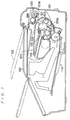
- the laser printer comprises, in a body frame 101, a laser beam scanning system 1, a sheet storage 110, an image formation cartridge 120, a fixing device 130, etc.
- a cover 102 is provided in an upper portion of the body frame 101 so as to pivot upward on a pin 103.
- the cover 102 serves as an ejected-sheet tray during printing operation, and when the cover 102 is lifted upward, maintenance of the internal parts is possible.
- Sheets are stacked in the sheet storage 110, and the sheets are fed out thereof one by one with rotation of a feed roller 111 and fed into a sheet path 120a in the image formation cartridge 120.
- the image formation cartridge 120 is a unit of a photosensitive drum 121, a transfer roller 122, a developing device 123, a residual toner cleaner 124, a residual charge eraser 125, etc.
- the Image formation cartridge 120 has a slit 126 which leads a laser beam emitted from the laser beam scanning system 1 to the photosensitive drum 121, and with rotation of the photosensitive drum 121 in a direction indicated with arrow c, an electrostatic latent image is formed thereon.
- the electrostatic latent image is developed by the developing device 123, and the developed image is transferred onto a sheet by discharge from the transfer roller 122.
- the sheet which has an image transferred is fed to the fixing device 130 through a sheet path 120b, and the transferred image is fixed thereon. Then, the printed sheet is ejected onto the cover 102.
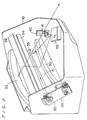
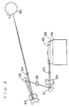
- Figs. 2, 3 and 4 show the composition of the laser beam scanning system 1.
- the laser beam scanning system 1 consists mainly of a housing 10 which is molded out of resin, a light source unit 20, and a photosensor 30 for detecting a printing start position (hereinafter referred to as SOS sensor), a polygonal mirror 45, a toric lens 50 and a toroidal mirror 53.
- a laser beam emitted from the light source unit 20 is reflected by a plane mirror 40, passes through a cylindrical lens 41 and is incident to the polygonal mirror 45.
- the polygonal mirror 45 has four deflecting facets on the periphery and is driven by a motor 46 to rotate in a direction indicated with arrow a at a constant speed. Thereby, the laser beam deflected by the deflecting facets of the polygonal mirror 45 is scanned in a plane at a constant angular velocity.
- the scanned laser beam passes through the toric lens 50 and is reflected by plane mirrors 51 and 52.
- the laser beam is further reflected by the toroidal mirror 53 and is imaged on the photosensitive drum 121 via a glass plate 54.
- the photosensitive drum 121 is driven to rotate in a direction indicated with arrow c.
- An electrostatic latent image is formed on the photosensitive drum 121 with the main scanning of the laser beam in the direction of arrow b and the rotation of the photosensitive drum 121 in the direction of arrow c (sub scanning).
- a plane mirror 35 is disposed after the plane mirror 51, just before the starting edge in the main scanning direction.
- a laser beam reflected by the plane mirror 51 at the starting edge is reflected by the plane mirror 35 and is incident to the SOS sensor 30. Based on the detection of the SOS sensor 30, scanning of each line on the photosensitive drum 121 is started.
- the light source unit 20 comprises, in a casing, a laser diode 71 which is a laser source (see Fig. 5), a photodiode 72 for monitoring the quantity of light (see Fig. 5) and a collimator lens (not shown) for collimating the laser beam.
- the light source unit 20 is fitted on the reverse side of a circuit board 25. On the front side of the circuit board 25, elements of a control circuit of the laser diode 71 are mounted.
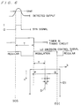
- control circuit 70 of the laser beam scanning system 1 and timing of switching the laser beam emission between regular emission and modulation emission.
- the laser diode 71 is controlled by an LD driving circuit 73 to perform regular emission and modulation emission. Meanwhile, the quantity of light of the emitted laser is detected by feedback. More specifically, the photodiode 72 monitors the quantity of light of a rear beam of the emitted laser, and the monitored data are sent back to the LD driving circuit 73. Image data are sent from an external appliance such as a host computer to an image memory 74 and further sent to the LD driving circuit 73 via a timing circuit 75. The timing circuit 75 also sends a control signal to a driving circuit 76 of the polygonal mirror motor 46.
- the laser beam of regular emission is detected by the SOS sensor 30 in due time. Then, the detected output is amplified by an amplifier 77 and compared with a threshold voltage V ref (see Fig. 6) by a comparator 78. If the output of the amplifier 77 is larger than the threshold voltage V ref , the comparator 78 generates a signal of "1" (synchronization signal), and if the output is smaller than the threshold voltage V ref , the comparator 78 generates a signal of "0". The output of the comparator 78 is sent to the timing circuit 75. The timing circuit 75 waits a specified time T after the output of the comparator 78 changes from "0" to "1" and starts calling one-line image data from the image memory 74. Then, the LD driving circuit 73 drives the laser diode 71 in accordance with the image data, and thus, modulation emission is performed.
- the straight line S can be printed accurately.
- the polygonal mirror motor 46 cannot keep the constant speed during the period T + t from the moment SOS, the scanning by the polygonal mirror 45 will cause an error. For example, a dot will be printed at a point y which is out of the right position to form a correct straight line S, and image disorder will occur.
- Such image disorder is remarkable when a brush motor is used as the polygonal mirror motor 46.
- the following describes the composition of the polygonal mirror motor 46 and a technique to avoid affects of the inconstant rotating speed of the motor 46 and to prevent the image disorder.
- Figs. 7 through 10 show the composition of the polygonal mirror motor 46.
- the motor 46 has an armature core 61 with three coils 62 and a three-segmented commutator 63a, 63b and 63c around a rotary shaft 60, and the armature core 61 is capable of freely rotate inside a magnet 64.
- a mirror rest 68 is pressed and fitted on the rotary shaft 60, and the polygonal mirror 45 is fixed on the mirror rest 68 by a screw 69. Thereby, the polygonal mirror 45 becomes possible to rotate with the rotary shaft 60.
- the circumferences of the commutator segments 63a, 63b and 63c are in contact with brushes 65, and thereby, a current supplied from a power source 66 is lead to the coils 62.
- a current supplied from a power source 66 is lead to the coils 62.
- Mutual reaction of the current flowing in the coils 62 and a magnetic flux of the magnet 64 generates a torque, and consequently, the rotary shaft 60 rotates together with the armature core 61.
- Fig. 11 shows the driving circuit 76 of the polygonal mirror motor 46.
- a switch SW closes on receiving the control signal from the timing circuit 75. Thereby, the coils 62 is supplied with a current, and the rotary shaft 60 rotates.
- An IC 79 is a control integral circuit (specifically, AN6652 manufactured by Matsushita Electric Co., Ltd.) to keep the rotating speed of the motor 46 constant.
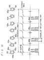
- Fig. 12 shows occurrences of commutation, the current wave of the motor 46 and the effective regions of the deflecting facets 45a, 45b, 45c and 45d of the polygonal mirror 45 while the motor 46 makes one rotation.
- the effective regions of the deflecting facets 45a, 45b, 45c and 45d of the polygonal mirror 45 mean the regions of the respective facets 45a, 45b, 45c and 45d where the laser beam is deflected for scanning from SOS to EOI. Further, Fig.
- FIG. 12 shows a case wherein the laser beam is incident to the polygonal mirror 45 at a right angle to the brushes 65 (see Fig. 13). Circles in Fig. 12 indicate moments of commutation.
- the current of the motor 46 changes largely in these moments, but is stable in other periods. In moments of commutation, an induced voltage occurs, and the torque and accordingly the rotating speed of the motor 46 changes. However, in periods other than the moments of commutation, the motor 46 can keep the rotating speed constant as a brushless motor does.
- the effective regions of the deflecting facets 45a, 45b, 45c and 45d are set such that the effective deflecting periods from SOS to EOI are out of the moments of commutation.
- a brush motor is used as the polygonal mirror motor 46, affects of commutation can be avoided, and image disorder can be prevented.
- the straight line S shown in Fig. 6 can be printed accurately.
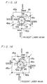
- Fig. 13 shows the effective regions (shadowed regions) and commutation positions (indicated with circles) of the deflecting facets 45a, 45b, 45c and 45d of the polygonal mirror 45 in a case wherein the laser beam is incident to the polygonal mirror 45 at a right angle to the brushes 6.
- the commutation positions mean positions where the polygonal mirror 45 deflects the laser beam in the moments of commutation.
- the commutation positions depend on the segmentation of the commutator, and in this embodiment, the commutation positions are located on equally six-divided points on the circumference.
- the polygonal mirror motor 46 has a bracket 85 which is protruded outside (see Fig. 15), and the brushes 65 are fixed on the bracket 85. Therefore, the positions of the brushes 65 can be recognized from outside.
- the polygonal mirror motor 46 is fitted to the housing 10 such that the laser beam will be incident to the polygonal mirror 45 at a right angle to the brushes 65.
- a fitting portion which will engage with the protrusion of the bracket 85 should be prepared in the housing 10.
- the positional relationship between the brushes 65 and the laser beam is determined, and thereafter, the polygonal mirror 45 is fitted to the rotary shaft 60 such that the deflecting facets of the polygonal mirror 45 will be desirably positioned with respect to the commutator segments 63a, 63b and 63c.
- the deflecting facets 45a, 45b, 45c and 45d are designed to have effective regions SOS through EOI located as shown in Fig. 13.
- the commutation positions are located at regular angles of 60 degrees from the rotation axis of the motor 45.
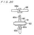
- Fig. 20 shows an exemplary way of setting the polygonal mirror 45 in the position shown in Fig. 13.
- the rotary shaft 60 has, on the upper portion, a mark 60a indicating the gap between the commutator segments 63a and 63b.
- the mirror rest 68 has a mark 68a on a side.
- the mirror rest 68 is pressed and fixed on the rotary shaft 60 such that the marks 60a and 68a will coincide.
- a person in the assembly line can see the mark 68a from outside, and the person places the mirror 45 on the mirror rest 68 watching the mark 68a.
- the polygonal mirror 45 can be fitted to the motor 46 such that the effective regions SOS through EOI of the deflecting facets are out of the commutation positions.
- the marks 60a and 68a may be provided on the rotary shaft 60 and the mirror rest 68.
- grooves may be provided on the rotary shaft 60 and the mirror rest 68.
- a recess which will be a reference of the positioning of the polygonal mirror 45 may be made on the upper surface of the mirror rest 68.
- the shaft holes of the rotary shaft 60 and the mirror rest 68 may be of a special configuration such as a triangle or any other polygon such that the deflecting facets of the polygonal mirror 45 will be positioned desirably with reference to the commutator segments 63a, 63b and 63c.
- Fig. 14 shows a case wherein the laser beam is incident to the polygonal mirror 45 at not a right angle to the brushes 65.
- the commutation positions which are indicated with circles, are different from those in the case of Fig. 13. This indicates that timing of occurrences of commutation in the main scanning direction can be changed by changing the positions of the brushes 65 with reference to the laser beam incident to the polygonal mirror 45.
- the commutation positions can be adjusted.
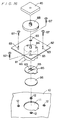
- Figs. 15 and 16 show the composition for fitting of the motor 46 to the housing 10.
- the frame 81 of the motor 46 is fixed to a fitting board 82 by vises 84.
- the mirror rest 68 and the polygonal mirror 45 are fitted to the rotary shaft 60 over the fitting board 82.
- the brushes 65 are fixed on the bracket 85, and the bracket 85 is fixed in the frame 81.
- the frame 81 is provided with a bottom plate 86 and is closed.
- the housing 10 has a hole 11 through which the motor frame 81 is fitted thereto, and on the periphery of the hole 11, four screw holes 12 are made.
- the fitting board 82 has four slots 83 at corresponding positions with the screw holes 12.
- the slots 83 are arcs on a concentric circle of the rotary shaft 60.
- the motor 46 is fixed on the housing 10 by screwing vises 87 into the holes 12 through the slots 83 of the fitting board 82. At that time, the fitting board 82 can be moved within the length of the slots 83, and thereby, the set positions of the brushes 65 with respect to the incident angle of the laser beam can be adjusted. Thus, adjustment to position the effective regions SOS through EOI of the deflecting facets of the polygonal mirror 45 out of the commutation positions is possible.
- the laser diode 71 is driven for regular emission, and simultaneously the polygonal mirror 45 is rotated.
- the current wave of the power source of the motor 46 and the output wave of the comparator 78 are monitored by an oscilloscope.
- Fig. 17a shows wave patterns obtained in the monitor.
- the fitting board 82 By turning the fitting board 82, the positional relationship between the peaks of the current wave and the peaks of the output wave of the comparator 78 is changed. Accordingly, while watching the monitored wave patterns, a person in the assembly line should turn the fitting board 82 such that commutation will not occur in the effective deflecting periods from SOS to EOI.
- the vises 87 should be tightened up after adjusting the posture of the fitting board 82 in this way.
- the occurrences of commutation and the effective deflecting periods can have mutual relationship as shown by Fig. 12.
- the positional relationship between the commutator segments 63a, 63b and 63c and the deflecting facets of the polygonal mirror 45 does not have to be specific.
- the effective regions of the deflecting facets 45a, 45b, 45c and 45d should be set to correspond to 30-degree rotation of the motor 46 at the maximum. While the motor 46 is rotating by an angle of ⁇ , the laser beam is deflected in a range of 2 ⁇ . Accordingly, in this case, the effective regions should be set within a maximum range of 60-degree deflection of the laser beam.
- the field angle is larger, for example, if each of the effective regions SOS through EOI of the deflecting facets requires a 65-degree deflection range of the laser beam as shown in Fig. 18, at least one effective region SOS through EOI will include a commutation position. Even in this case, if the commutation position is set as close as possible to EOI, the influence of the commutation on the image can be avoided to the utmost.
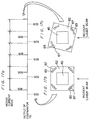
- Fig. 19 is a graph plotting time on the x-axis versus printing position on the photosensitive drum 121 in the main scanning direction on the y-axis. Referring to Fig. 19, by the deflecting facets 45a and 45c, printing is carried out as indicated with a line OABC, and the printing position at the time of EOI is a point a.
- the effective regions of the second deflecting facet 45b and the fourth deflecting facet 45d include commutation positions, and printing by these deflecting facets 45b and 45d is not carried out as indicated with the line OABC.
- the printing position at the time of EOI is a point b.
- the distance (a-b) between the point b and the point a which is the correct printing position is large, and the image disorder caused thereby is remarkable.
- the printing will be carried out as indicated with a line OABEF.
- the printing position at the time of EOI is a point c.
- the distance (a-c) between the point c and the point a is much smaller than the distance (a-b), and the image disorder caused thereby is not practically a problem.
- the maximum sheet size usable in the laser printer is a letter size
- the printing position at the time of EOI (point a) is the point of 215.9mm. If the commutation positions included in the effective regions of the second and the fourth deflecting facets 45b and 45d are set at points corresponding to 60-degree deflection from the deflection angles of the laser beam at the respective times of SOS, the printing position at the times of commutation is 199.3mm (215.9 ⁇ 60/65). Thus, in this case, image disorder will not be caused by the commutation in printing on an A5-sized sheet (148.0mm in length of main scanning).
- the changes in the rotating speed of the motor 46 caused by the occurrences of commutation do not always agree with the lines AD and BE.
- the line AB is a model of the rotating speed of the motor 46 with no occurrences of commutation
- the lines AD and BE are models of reductions in the rotating speed with the occurrences of commutation.
- the motor 46 with the three-segmented commutator 63a, 63b and 63c (six commutation positions) and the polygonal mirror 45 with four deflecting facets are combined, and it is rather difficult to set the effective regions of the deflecting facets out of the commutation positions.
- the effective regions of the deflecting facets must be set small, and high accuracy is required for fitting the polygonal mirror 45 to the motor 46 and for fitting the motor 46 to the housing 10.
- a combination of the motor 45 with the three-segmented commutator and a polygonal mirror 47 with six deflecting facets solves the above problem.
- the six commutation positions can be set at the borders 47x among the six deflecting facets of the polygonal mirror 47, and thereby, the effective regions can be set larger and more freely on the respective deflecting facets. Additionally, fitting the polygonal mirror 47 to the motor 46 and fitting the motor 46 to the housing 10 do not require so high accuracy.
- a motor with a three-segmented commutator is used as the motor 46 of the polygonal mirror 45, but any other motor with any number of commutator segments may be used.
- the brushes are fixed, while the commutator rotates.
- the brushes and the commutator can be made so as to rotate and to be fixed respectively.
- the present invention is applicable widely to an image reader, a two-dimensional image display and the like as well as a print head of a laser printer.
Landscapes
- Engineering & Computer Science (AREA)
- Multimedia (AREA)
- Signal Processing (AREA)
- Facsimile Scanning Arrangements (AREA)
- Mechanical Optical Scanning Systems (AREA)
Applications Claiming Priority (4)
| Application Number | Priority Date | Filing Date | Title |
|---|---|---|---|
| JP13625993 | 1993-06-07 | ||
| JP136259/93 | 1993-06-07 | ||
| JP185038/93 | 1993-07-27 | ||
| JP5185038A JPH0756099A (ja) | 1993-06-07 | 1993-07-27 | 回転偏向器及び光ビーム走査光学装置 |
Publications (3)
| Publication Number | Publication Date |
|---|---|
| EP0629074A2 true EP0629074A2 (de) | 1994-12-14 |
| EP0629074A3 EP0629074A3 (de) | 1995-12-06 |
| EP0629074B1 EP0629074B1 (de) | 1998-08-26 |
Family
ID=26469889
Family Applications (1)
| Application Number | Title | Priority Date | Filing Date |
|---|---|---|---|
| EP94108623A Expired - Lifetime EP0629074B1 (de) | 1993-06-07 | 1994-06-06 | Drehbarer Abtaster |
Country Status (4)
| Country | Link |
|---|---|
| US (1) | US5488225A (de) |
| EP (1) | EP0629074B1 (de) |
| JP (1) | JPH0756099A (de) |
| DE (1) | DE69412707T2 (de) |
Families Citing this family (3)
| Publication number | Priority date | Publication date | Assignee | Title |
|---|---|---|---|---|
| US6459443B1 (en) | 2001-06-21 | 2002-10-01 | Lexmark International, Inc | Method of minimizing print delay due to mirror motor warm-up in an electrophotographic machine |
| DE10310602A1 (de) * | 2003-03-11 | 2004-09-23 | Olympus Biosystems Gmbh | Zwischen wenigstens zwei optischen Systemen abbildende optische Abbildungsanordnung mit wenigstens einem torischen Spiegel |
| CN106787462B (zh) * | 2015-11-25 | 2020-10-23 | 德昌电机(深圳)有限公司 | 电机驱动组件 |
Citations (3)
| Publication number | Priority date | Publication date | Assignee | Title |
|---|---|---|---|---|
| JPS59220058A (ja) * | 1983-05-25 | 1984-12-11 | Takahashi Yoshiteru | 4極の界磁々極、5巻線、10セグメントの整流子片を有する整流子によつて構成されるトルクリツプルの極めて少ない効率良好な5相の直流電動機 |
| EP0491207A2 (de) * | 1990-12-17 | 1992-06-24 | Eastman Kodak Company | Vorrichtung zur Ausrichtung eines optischen Bauteiles |
| US5184038A (en) * | 1990-01-23 | 1993-02-02 | Kawasaki Jukogyo Kabushiki Kaisha | Method of coupling magnetic position detecting device with brushless dc motor and the coupling structure thereof |
Family Cites Families (7)
| Publication number | Priority date | Publication date | Assignee | Title |
|---|---|---|---|---|
| US3662198A (en) * | 1970-12-04 | 1972-05-09 | John Adams Jr | Traction motor inspection cover |
| JPS58142025A (ja) * | 1982-02-13 | 1983-08-23 | Toshiba Corp | スピンドル装置 |
| US4623216A (en) * | 1983-02-10 | 1986-11-18 | Canon Kabushiki Kaisha | Light beam scanning apparatus |
| US4631463A (en) * | 1985-02-14 | 1986-12-23 | Rockwell International Corporation | Linear controller for electrochemical device and method |
| NL8501142A (nl) * | 1985-04-19 | 1986-11-17 | Oce Nederland B V Patents And | Omwentelingslichaam, in het bijzonder polygoonspiegel. |
| ES2048786T3 (es) * | 1988-06-09 | 1994-04-01 | Hohe Kg | Espejo retrovisor exterior para un vehiculo con marcha atras. |
| US5033835A (en) * | 1988-12-09 | 1991-07-23 | Platzer Jr George E | Remote control mirror with angular viewing adjustments |
-
1993
- 1993-07-27 JP JP5185038A patent/JPH0756099A/ja active Pending
-
1994
- 1994-06-03 US US08/253,341 patent/US5488225A/en not_active Expired - Fee Related
- 1994-06-06 EP EP94108623A patent/EP0629074B1/de not_active Expired - Lifetime
- 1994-06-06 DE DE69412707T patent/DE69412707T2/de not_active Expired - Lifetime
Patent Citations (3)
| Publication number | Priority date | Publication date | Assignee | Title |
|---|---|---|---|---|
| JPS59220058A (ja) * | 1983-05-25 | 1984-12-11 | Takahashi Yoshiteru | 4極の界磁々極、5巻線、10セグメントの整流子片を有する整流子によつて構成されるトルクリツプルの極めて少ない効率良好な5相の直流電動機 |
| US5184038A (en) * | 1990-01-23 | 1993-02-02 | Kawasaki Jukogyo Kabushiki Kaisha | Method of coupling magnetic position detecting device with brushless dc motor and the coupling structure thereof |
| EP0491207A2 (de) * | 1990-12-17 | 1992-06-24 | Eastman Kodak Company | Vorrichtung zur Ausrichtung eines optischen Bauteiles |
Non-Patent Citations (1)
| Title |
|---|
| PATENT ABSTRACTS OF JAPAN vol. 9 no. 89 (E-309) ,18 April 1985 & JP-A-59 220058 (YOSHITERU TAKAHASHI) 11 December 1984, * |
Also Published As
| Publication number | Publication date |
|---|---|
| JPH0756099A (ja) | 1995-03-03 |
| EP0629074A3 (de) | 1995-12-06 |
| EP0629074B1 (de) | 1998-08-26 |
| DE69412707T2 (de) | 1999-05-06 |
| DE69412707D1 (de) | 1998-10-01 |
| US5488225A (en) | 1996-01-30 |
Similar Documents
| Publication | Publication Date | Title |
|---|---|---|
| EP1788421B1 (de) | Abtastvorrichtung mit Schwingspiegel und Bilderzeugungsvorrichtung | |
| EP2236300B1 (de) | Bilderzeugungsvorrichtung | |
| US10191403B2 (en) | Image forming apparatus | |
| EP0689339B1 (de) | Laserdrucker mit Gerät zur Verminderung des Bandeffektes verursacht durch unebene Trennung von aufeinanderfolgenden Abtastzeilen | |
| US6646668B2 (en) | Image forming apparatus for maintaining a constant beam scanning state | |
| JP6824653B2 (ja) | 画像形成装置 | |
| US20120293849A1 (en) | Multi-beam light source device, optical scanning device, and image forming apparatus | |
| US8259150B2 (en) | Image forming apparatus | |
| US4323919A (en) | Optical scanner for reading data recorded in plural colors | |
| EP0450643A2 (de) | Optischer Abtaster | |
| EP0629074B1 (de) | Drehbarer Abtaster | |
| EP0454438A1 (de) | Rotationsapparat, welcher in einem dynamischen Fluid gelagert ist | |
| US5576536A (en) | Image forming apparatus including motor-driven rotary scanner and system for judging if motor rotation comes to steady state and for maintaining rotation at steady state | |
| US10108104B2 (en) | Method and apparatus for controlling multiple beam spacing | |
| US6055083A (en) | Optical scanning unit module and optical scanning system adopting the same | |
| JP2004034608A (ja) | 光源装置及び画像形成装置 | |
| JPH0764009A (ja) | 画像形成装置 | |
| JPH0756101A (ja) | 画像形成装置 | |
| JPH0415613A (ja) | レーザビーム走査位置検出構造 | |
| JP3000473B2 (ja) | 画像形成装置 | |
| JP3568175B2 (ja) | 光ビーム走査装置 | |
| JP3096987B2 (ja) | 画像形成装置 | |
| JPH09107445A (ja) | 光ビーム走査装置 | |
| JPH0915516A (ja) | 光走査装置 | |
| JPH0777661A (ja) | 光走査装置 |
Legal Events
| Date | Code | Title | Description |
|---|---|---|---|
| PUAI | Public reference made under article 153(3) epc to a published international application that has entered the european phase |
Free format text: ORIGINAL CODE: 0009012 |
|
| AK | Designated contracting states |
Kind code of ref document: A2 Designated state(s): DE FR GB |
|
| PUAL | Search report despatched |
Free format text: ORIGINAL CODE: 0009013 |
|
| AK | Designated contracting states |
Kind code of ref document: A3 Designated state(s): DE FR GB |
|
| 17P | Request for examination filed |
Effective date: 19960207 |
|
| RAP1 | Party data changed (applicant data changed or rights of an application transferred) |
Owner name: MINOLTA CO., LTD. |
|
| 17Q | First examination report despatched |
Effective date: 19970409 |
|
| GRAG | Despatch of communication of intention to grant |
Free format text: ORIGINAL CODE: EPIDOS AGRA |
|
| GRAG | Despatch of communication of intention to grant |
Free format text: ORIGINAL CODE: EPIDOS AGRA |
|
| GRAH | Despatch of communication of intention to grant a patent |
Free format text: ORIGINAL CODE: EPIDOS IGRA |
|
| GRAH | Despatch of communication of intention to grant a patent |
Free format text: ORIGINAL CODE: EPIDOS IGRA |
|
| GRAA | (expected) grant |
Free format text: ORIGINAL CODE: 0009210 |
|
| AK | Designated contracting states |
Kind code of ref document: B1 Designated state(s): DE FR GB |
|
| REF | Corresponds to: |
Ref document number: 69412707 Country of ref document: DE Date of ref document: 19981001 |
|
| ET | Fr: translation filed | ||
| PLBE | No opposition filed within time limit |
Free format text: ORIGINAL CODE: 0009261 |
|
| STAA | Information on the status of an ep patent application or granted ep patent |
Free format text: STATUS: NO OPPOSITION FILED WITHIN TIME LIMIT |
|
| 26N | No opposition filed | ||
| REG | Reference to a national code |
Ref country code: GB Ref legal event code: IF02 |
|
| PGFP | Annual fee paid to national office [announced via postgrant information from national office to epo] |
Ref country code: DE Payment date: 20120530 Year of fee payment: 19 |
|
| PGFP | Annual fee paid to national office [announced via postgrant information from national office to epo] |
Ref country code: FR Payment date: 20120619 Year of fee payment: 19 Ref country code: GB Payment date: 20120606 Year of fee payment: 19 |
|
| GBPC | Gb: european patent ceased through non-payment of renewal fee |
Effective date: 20130606 |
|
| REG | Reference to a national code |
Ref country code: DE Ref legal event code: R119 Ref document number: 69412707 Country of ref document: DE Effective date: 20140101 |
|
| REG | Reference to a national code |
Ref country code: FR Ref legal event code: ST Effective date: 20140228 |
|
| PG25 | Lapsed in a contracting state [announced via postgrant information from national office to epo] |
Ref country code: DE Free format text: LAPSE BECAUSE OF NON-PAYMENT OF DUE FEES Effective date: 20140101 Ref country code: GB Free format text: LAPSE BECAUSE OF NON-PAYMENT OF DUE FEES Effective date: 20130606 |
|
| PG25 | Lapsed in a contracting state [announced via postgrant information from national office to epo] |
Ref country code: FR Free format text: LAPSE BECAUSE OF NON-PAYMENT OF DUE FEES Effective date: 20130701 |