EP0629032B1 - Dispositif pour effectuer le traitement de charge et révitalisation de batteries - Google Patents
Dispositif pour effectuer le traitement de charge et révitalisation de batteries Download PDFInfo
- Publication number
- EP0629032B1 EP0629032B1 EP93830259A EP93830259A EP0629032B1 EP 0629032 B1 EP0629032 B1 EP 0629032B1 EP 93830259 A EP93830259 A EP 93830259A EP 93830259 A EP93830259 A EP 93830259A EP 0629032 B1 EP0629032 B1 EP 0629032B1
- Authority
- EP
- European Patent Office
- Prior art keywords
- battery
- charging
- module
- charge
- batteries
- Prior art date
- Legal status (The legal status is an assumption and is not a legal conclusion. Google has not performed a legal analysis and makes no representation as to the accuracy of the status listed.)
- Expired - Lifetime
Links
Images


Classifications
-
- H—ELECTRICITY
- H02—GENERATION; CONVERSION OR DISTRIBUTION OF ELECTRIC POWER
- H02J—CIRCUIT ARRANGEMENTS OR SYSTEMS FOR SUPPLYING OR DISTRIBUTING ELECTRIC POWER; SYSTEMS FOR STORING ELECTRIC ENERGY
- H02J7/00—Circuit arrangements for charging or depolarising batteries or for supplying loads from batteries
- H02J7/0069—Charging or discharging for charge maintenance, battery initiation or rejuvenation
-
- H—ELECTRICITY
- H02—GENERATION; CONVERSION OR DISTRIBUTION OF ELECTRIC POWER
- H02J—CIRCUIT ARRANGEMENTS OR SYSTEMS FOR SUPPLYING OR DISTRIBUTING ELECTRIC POWER; SYSTEMS FOR STORING ELECTRIC ENERGY
- H02J7/00—Circuit arrangements for charging or depolarising batteries or for supplying loads from batteries
- H02J7/0013—Circuit arrangements for charging or depolarising batteries or for supplying loads from batteries acting upon several batteries simultaneously or sequentially
-
- H—ELECTRICITY
- H02—GENERATION; CONVERSION OR DISTRIBUTION OF ELECTRIC POWER
- H02J—CIRCUIT ARRANGEMENTS OR SYSTEMS FOR SUPPLYING OR DISTRIBUTING ELECTRIC POWER; SYSTEMS FOR STORING ELECTRIC ENERGY
- H02J7/00—Circuit arrangements for charging or depolarising batteries or for supplying loads from batteries
- H02J7/007—Regulation of charging or discharging current or voltage
- H02J7/00712—Regulation of charging or discharging current or voltage the cycle being controlled or terminated in response to electric parameters
- H02J7/00714—Regulation of charging or discharging current or voltage the cycle being controlled or terminated in response to electric parameters in response to battery charging or discharging current
-
- H—ELECTRICITY
- H02—GENERATION; CONVERSION OR DISTRIBUTION OF ELECTRIC POWER
- H02J—CIRCUIT ARRANGEMENTS OR SYSTEMS FOR SUPPLYING OR DISTRIBUTING ELECTRIC POWER; SYSTEMS FOR STORING ELECTRIC ENERGY
- H02J7/00—Circuit arrangements for charging or depolarising batteries or for supplying loads from batteries
- H02J7/007—Regulation of charging or discharging current or voltage
- H02J7/00712—Regulation of charging or discharging current or voltage the cycle being controlled or terminated in response to electric parameters
- H02J7/007182—Regulation of charging or discharging current or voltage the cycle being controlled or terminated in response to electric parameters in response to battery voltage
Definitions
- the present invention relates to a device for charging and revitalizing electric batteries, and more particularly sealed Ni-Cd batteries.
- Such devices are commonly employed in different sectors in which an isolated power source is needed, particularly in electric or electronic field equipments, e.g. transceivers, portable terminals, remote control devices, and the like.
- Ni-Cd battery recharging devices particularly for charging the above mentioned sealed type.
- One of the most relevant problems to be solved in designing such devices is to reliably detect when the condition of full charge has been achieved for any of different types of batteries, thus preventing their overcharging.
- WO-A-90/06615 discloses a device for charging and revitalising one or more batteries at the same time and it comprises:
- DE-A-3700092 deals with simultaneous charging of a plurality of batteries and discloses comparators for monitoring input and output voltages and means for manually starting and stopping a treatment process in each channel and means for selecting the kind of treatment each battery has to be subject to and the mode of process.
- EP-A-0470065 deals also with simultaneous charging of a plurality of batteries and proposes means for monitoring over- and undervoltages, polarity reversal as well as means for selecting programs and parameters.
- An object of the present invention is that of providing a device for recharging Ni-Cd batteries, that is capable of effectively dealing with more batteries of different types at the same time.
- a further object of the present invention is that of providing a device capable of simultaneously recharging two or more sealed Ni-Cd batteries that allows the recharging of each battery in a quick and safe way.
- a further object of the present invention is to obtain a device for simultaneously recharging two or more sealed Ni-Cd batteries and that is further capable of automatically carrying out a revitalizing process.
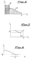
- Figure 1 shows the main components that are mounted on the front panel of the battery treating device 1 according to the invention.
- the device 1 is supplied by an external power source (not shown) through the power supply connector 2.
- the feeding voltage is comprised in a range from 10 to 32 volts and preferably is 24 volts.
- an on/off switch 3 for energizing the device 1, a pilot lamp 4 indicating the on condition of the device 1 and a fuse 5 for the protection against possible malfunctions in the power line.
- the device 1 is connected to a battery housing (not shown) through an output connector 6.
- the device 1 is equipped with four independent channels for simultaneously handling four batteries, even of different type from one another.
- each switch 7 causes the start of the treatment or its stop during the process, while in the other position each switch 7 causes an indication of the percentage of the battery charging over the corresponding channel to be displayed in alphanumeric form on a display 10.
- the red LEDs 8a-8d and the green LEDs 9a-9d are used for continuously indicating the process conditions of each channel.
- the permanent lighting of a LED 8 indicates either that a battery is connected to the associated channel, or that a battery is being discharged in a step of a revitalizing process; the LED is turned off either when a charging process is started by actuating the corresponding switch 7, or when a battery is being charged in a step of a revitalizing process.
- a flashing condition of a LED 8 indicates a malfunction in the corresponding channel.
- the permanent lighting of a LED 9 indicates that a treatment process is in progress in the corresponding channel, while the flashing condition of a LED 9 indicates that the process has been completed. In this case the device 1 maintains nevertheless a trickle charge in the corresponding channel until the process is stopped by acting on the corresponding switch 7.
- a three-position switch 11 is used to select one of the device functions: i.e a charge treatment, a revitalizing treatment or a general test of the device conditions and the batteries connected thereto.
- a similar three-position switch 12 is used to select one of the available charging rates, i.e. slow, standard, fast.
- a push-button 13 is provided for stopping acoustic and/or visual warning signals from the device in case of troubles or failures. By pushing such button, the operator acknowledges the warning and enables the device to show on the alphanumeric display 10 a code of the trouble or failure.
- a switch 14 for excluding any warning signal from the device without stopping the working thereof. This feature is particularly useful when it is desired to prevent the device from being located, e.g. in military applications when the device in being used during a mission requiring that enemy interception be prevented.
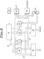
- Figure 2 shows a general block diagram of the device including an interconnecting board 20 to which the different modules of the device 1 are connected.
- an external interface module 21 for handling the switching signals generated when the switches and push-buttons located on the device front panel are actuated ( Figure 1), as well as for handling the warning signals on the front panel and any outwardly exchange of data through a serial interface of the RS-232 type; a module 22 for protecting both the device and the batteries against voltage swings or polarity reversal of the connected power source, as well as for filtering the input and output signals of the device; a power supply and control module 23 capable of supplying the voltages required for the device operation, as well as of checking the battery conditions; a microprocessor logic module 24 controlling both the battery treatment processes and the device functions; an analog module 25 for detecting and controlling the voltages and currents supplied to the batteries under charge; a charge/discharge module 26 for providing the charge/discharge sources for each channel.
- the revitalizing treatment subjects a battery to a series of charge and discharge cycles.
- the device there are provided from one to eight charge/discharge cycles, the first of which having a predetermined duration. More particularly the first charge process has a fixed duration of seven hours, whereas the subsequent ones are terminated in accordance with the standard methods for stopping the charge; the number of cycles is automatically determined by the device depending on the restored electric capacity at the end of each cycle.
- the device 1 through the logic module 24, accomplishes a constant-current or constant-voltage charge depending on the environment temperature and on the voltage across each battery.
- the charge process is first set at a constant current and it is so maintained till the voltage of the battery reaches the maximum allowed value, usually the one recommended by the manufacturer and being approximately in the range 1.6-1.7 volts.
- the environment temperature is lower than a predetermined reference temperature, usually in the range from 0 °C to 5 °C, the device automatically switches to a constant-voltage charge.
- the device automatically switches to a constant-current charge condition, at a charging rate lower than the previous one, i.e. from “fast” to "standard”, or from “standard” to “slow", when the voltage at the battery terminals reaches the maximum allowed value.
- the current charging rate is already the minimum rate allowed by the device, i. e. the "slow” charging rate
- the device automatically switches into a constant-voltage charge condition when the voltage at the battery terminals reaches again the maximum allowed value.
- the charging process is determined as completed when one of the following events takes place:
- the maximum duration of a charge process changes as a function of the selected charge mode, that is fourteen hours for a "slow” charging process, five hours for a "standard” charging process, and two hours for a "fast” charging process.
- the charging process is nevertheless stopped after a predetermined time interval to prevent possible damages to the battery.
- the maximum duration of a charging process changes depending on the selected charging mode, that is twenty hours for a "slow” charging process, six hours and thirty minutes for a "standard” charging process, and three hours for a "fast” charging process.
- the device 1 subjects the battery to a trickle charging step that preserves the battery charge conditions at the same time preventing any risk of overcharge and consequently of battery damages.
- the control and the execution of the different functions of the device 1 are carried out by the microprocessor logic module 24. More particularly, there are performed diagnostic tests in the device when power is turned on to detect possible malfunctions thereof, functions for automatically identifying the type, capacity and charging conditions of each battery, functions for detecting the conditions of open circuit, closed circuit and polarity reversal of each battery, functions for automatically selecting the modes and the charging rate for each battery in accordance with the conditions thereof and the temperature condition of the working environment, functions for automatically selecting the number of the charge and discharge cycles in the revitalizing process for each battery in accordance with its conditions, functions for monitoring the treatment processes to detect possible failures or malfunctions in the device or in the batteries, functions for determining the completion of the process for each battery and for maintaining a trickle charge condition, when the first condition is met, as well as functions for controlling said means for warning about events related to the working of the device and to the running processes.
- Figure 9 shows a block diagram of the logic module 24 in which a microprocessor 40 is provided that operates in accordance with a program stored in an EPROM memory unit 41.
- One or more RAM memory units 42 store the parameters of the batteries or those of predetermined battery arrangements. The values of these parameters can be modified by means of an external terminal connected to a standard RS-232 serial port ( Figure 14), provided on the external interface module 21, and connected in turn to a port 43 of the USART type, for allowing the conversion of parallel bit patterns into corresponding serial streams.
- a clock device 44 sets the operating frequency of the microprocessor 40 and provides a time base to a timer 45.
- a standby battery (not shown) connected to the RAM memory units, for maintaining the stored data when the external power source is off.
- the exchange of the command and/or control signals with the remaining modules of the device is achieved through a pair of parallel ports 46 and 47, a buffer 48 and a control device 49 controlling the asynchronous interruption conditions. More particularly the parallel port 46 is connected to the analog module 25, the parallel port 47 is connected to the power supply and control module 23, to the charge/discharge module 26 and to the analog module 25, the buffer 48 is connected to the external interface module 21, and the device 49 controlling the asynchronous interruption conditions to the external interface module 21, to the power supply and control module 23 and to the charge/discharge module 26.
- the connection between the units of the logic module 24 is accomplished through the bus lines 50, 51, for the address exchange, and a bus line 52 for the data exchange.
- An "address latch" device 53 allows for reading the addresses (less significant bits) on the line 51, and transferring them over the line 51 of the address bus.
- Figure 10 shows the block diagram of the analog module 25 including a twelve bit digital to analog converter 60, connected to the logic module 24, and a plurality of analog multiplexers allowing for the voltage measurement at the battery terminals, the measurement of the battery charge or discharge currents and the control of the battery charge current. More particularly it is provided a main multiplexer 61 for applying one of the four input voltage signals to a comparator 62.
- the input voltages of the main multiplexer 61 are a function of the process values (voltages and currents, either detected or supplied to the batteries), as well as of the environment temperature.
- the comparator 62 produces an output signal for the logic module 24 by comparing the signal from the main multiplexer 61 with a signal produced by the converter 60 on the basis of a reference signal 63.
- a multiplexer 64 selects one of the four output voltage signals from the current detecting units 65a-65d connected to the charge/discharge module 26.
- a polarity reversing device 66 is connected between the multiplexer 64 and the multiplexer 61, for reading the opposite polarity signal during the discharge processes.
- the reading of the output voltages from the charge/discharge module 26 is accomplished by units 68a-68d adapted to detect voltages in the four channels, whereas the selection of one of the four signals is achieved through a multiplexer 67.
- the connecting line 69 from the external interface module 21, carries a voltage signal representing the temperature of the environment in which processes are taking place.
- a demultiplexer device 70 For controlling the charge and discharge currents in the four channels a demultiplexer device 70 is provided that applies the voltage signal from the converter 60 to one of the four voltage holding circuits 71a-71d. The voltages at the outputs of circuits 71a-71d are applied to the charge/discharge module 26 and to the circuits 72a-72d driving the MOSFET devices of said module 26.
- the input selection in the multiplexer devices 61, 64, 67 and the output selection in the demultiplexer 70, as well as the activation of the drive circuits 72a-72d are determined by the signals from the logic module 24.
- Figure 11 shows a block diagram of the power supply and control module 23.
- This latter includes a first converter 80 for converting the feed voltage rated at 24 volts d.c. from the drive and filter module 22 into a +15 volts d.c. and a -15 volts d.c. as requested for the battery treatment processes.
- a second converter 81 the 24 volts d.c. rated voltage is converted into a +5 volt d.c. voltage for the operation of the device 1.
- circuits 82a-82d for detecting possible short circuit and open circuit conditions of the batteries.
- Each circuit 82a-82d is actuated by a signal from the logic module 24 and sends back to the same module a binary signal indicating the state of the battery connected over the corresponding channel.
- Circuits 82a-82d drive corresponding relays in the protection module 22 for disconnecting a battery in case of a malfunction thereof.
- FIG. 12 reproduces a block diagram of the protection and filtering module 22.
- the already mentioned battery protection relays labelled as 90a-90d the already mentioned battery protection relays labelled as 90a-90d.
- a series of devices 93a-93d protect the batteries against possible polarity reversal.
- the relay 91 is driven by a circuit 92 for the protection against possible peaks of the feed voltage at switching on.
- the module 22 further includes the filters required to meet the interference requirements for the device 1 (EMI standards).
- a filter 94 is provided in the 24 volt d.c. supply line connected to the power supply and control module 23, as well as four filters 95a-95d on the connection lines of the corresponding channels that lead to the connector 6 ( Figure 1) on the front panel.
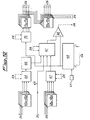
- FIG. 13 shows the block diagram of the battery charge/discharge module 26.
- This module includes the devices 100a-100d of the MOSFET type for discharging the batteries in the revitalizing processes, the circuits 101a-101d for sensing the battery currents, as well as a series of circuits and devices for monitoring the charge voltages and currents. More particularly they comprise four voltage-programmed drive circuits 102a-102d for the power supplied by the devices 103a-103d of the MOSFET type. These latter are serially connected transformer devices 104a-104d, rectifier devices 105a-105d and filtering devices 106a-106d for realizing the current sources with a limited power dissipation in the typical configurations of switching power supplies.
- FIG 14 shows the block diagram of the external interface module 21, that is the module that constitutes the interface between the operator and the microprocessor 40.
- the module 21 comprises a unit 100 of the "buffer latch" type for connecting the switching and signalling devices on the front panel ( Figure 1). More particularly the connections concern the four switches 7a-7d for starting and stopping the process over the channels, the switch 12 for selecting one of the charging rates, the push-button 13 for acknowledging the alarm signals and stopping the warning signals, the switch 14 for excluding the external signals without interruption of the device 1, as well as the LEDs 8a-8d, 9a-9d.
- the device 110 is also connected to a decoder circuit 111 for identifying the type of the battery housing and the bus line 114 carrying data from the buffer 48 of the logic module 24 to the display 10.
- the switch 3 for turning on the device 1, although included in module 21, is directly connected to the protection and filtering module 22.
- Additional connections to the logic module 24 comprise a serial line 115 for data transferring through an interface 112 of the RS-232 type, and a lead for energizing an acoustic signalling device 113.
- a temperature transducer 116 connected to an amplifier 117 provides the analog module 25 with a voltage value representative of the temperature of the environment in which the device is working.
Claims (14)
- Dispositif pour charger ou revitaliser simultanément une ou plusieurs batteries, comprenant :caractérisé en ce qu'il fournit une charge à courant constant et une commutation automatique vers une charge à voltage constant lorsque la tension aux bornes de batterie atteint une valeur maximale autorisée et que la température ambiante est inférieure à une température de référence prédéfinie, ainsi qu'une commutation automatique d'une charge à courant constant vers une charge à courant constant à un taux inférieur au précédent lorsque la tension aux bornes de la batterie atteint la valeur maximale et que la température ambiante est supérieure à la valeur de référence prédéfinie.une pluralité de voies indépendantes pour connecter chaque batterie au dispositif ;un module (23) d'alimentation et de commande conçu pour fournir au dispositif les niveaux de tension nécessaires à leur fonctionnement, et à commander le moyen de protection de la batterie ;un module (22) pour protéger le dispositif et les batteries en charge contre les fluctuations de tension ou l'inversion de polarité, ainsi que pour filtrer les signaux d'entrée et de sortie du dispositif ;un module (26) de charge/décharge fournissant les sources de charge/décharge à chaque voie ;un module (24) logique à microprocesseur pour commander à la fois les procédés des opérations de traitement auxquelles les batteries sont soumises et les fonctions du dispositif, ces procédés étant mis en oeuvre pour chaque voie d'une manière indépendante des caractéristiques de la capacité nominale, des conditions de recharge et des opérations sélectionnées pour les autres voies, ce module logique à microprocesseur comportant des moyens (41) pour mémoriser des programmes de commande et des moyens (42) pour mémoriser des paramètres relatifs aux procédés en cours ;un module (25) analogique de détection et de commande des tensions et courants fournis aux batteries ; etun module (21) externe d'interface comportant des moyens (7a,7b,7c,7d) pour démarrer et arrêter manuellement un procédé de traitement des opérations dans chaque voie, des moyens (11) pour sélectionner le mode de traitement auquel chaque batterie doit être soumise, des moyens (12) pour sélectionner le mode de chaque procédé, ainsi que des moyens pour afficher l'occurrence de certains événements relatifs au fonctionnement du dispositif, au déroulement du procédé et à l'état de la batterie,
- Dispositif selon la revendication 1,
caractérisé en ce que la température de référence est comprise entre 0°C et +5°C. - Dispositif selon la revendication 1,
caractérisé en ce que le module (24) logique est conçu pour déterminer l'achèvement du procédé de charge :soit lorsque le produit du courant fourni par la durée du procédé excède une valeur prédéfinie de la capacité nominale de la batterie, oulorsqu'il se produit une baisse de tension au niveau des bornes de la batterie durant un intervalle de temps prédéfini, oulorsqu'une augmentation de la tension au niveau des bornes de la batterie excède une valeur prédéfinie durant un intervalle de temps donné, oudans le cas où aucune des conditions ci-dessus n'est réalisée, lorsque la durée du procédé de charge excède une durée prédéfinie dépendant du mode de charge sélectionné. - Dispositif selon l'une quelconque des revendications 1 à 3, caractérisé en ce que le module (24) logique est conçu pour déterminer l'achèvement du procédé de charge de chaque batterie :lorsque le produit du courant fourni par la durée du procédé excède une valeur prédéfinie de la capacité nominale de la batterie, oulorsque le courant de charge augmente durant un intervalle de temps prédéfini dépendant du mode de charge sélectionné, oulorsque le courant de charge est inférieur à une fraction prédéfinie de la capacité nominale de la batterie, oudans le cas où aucune des conditions ci-dessus n'est réalisée, lorsque la durée du procédé de charge excède une durée prédéfinie dépendant du mode de charge sélectionné.
- Dispositif selon l'une quelconque des revendications 3 ou 4, caractérisé en ce qu'il réalise une durée de charge pulsée à la fin de chaque période de charge ou de revitalisation.
- Dispositif selon la revendication 1,
caractérisé en ce que le module (22) de protection comprend une pluralité de relais (90a-90d) commandés par des circuits (93a-93d) existant dans le module d'alimentation. - Dispositif selon la revendication 1,
caractérisé en ce que le module (26) de charge/décharge comprend des sources d'énergie (102-108) conçues pour réduire le pouvoir de dissipation et des dispositifs (100a-100d) du type MOSFET pour décharger les batteries durant les opérations de revitalisation. - Dispositif selon la revendication 1,
caractérisé en ce que les moyens de mémoire du module (24) logique à microprocesseur comportent une unité (41) de mémoire morte programmable effaçable EPROM pour mémoriser les programmes de commande et une ou plusieurs unités (42) de mémoire à accès sélectif RAM pour mémoriser les paramètres relatifs aux procédés de fonctionnement. - Dispositif selon la revendication 8,
caractérisé en ce que le module (21) externe d'interface comprend une ligne (115) série RS-232 reliée à un port (43) du type USART dans le module (24) logique pour permettre la connexion à des systèmes périphériques externes conçus pour stocker dans la mémoire (42) à accès sélectif RAM une pluralité de paramètres relatifs aux différents groupements de batteries. - Dispositif selon la revendication 8,
caractérisé en ce que il comprend une batterie de réserve associée aux unités (42) de mémoire à accès sélectif RAM pour conserver les données mémorisées lorsque la source d'énergie externe est éteinte. - Dispositif selon la revendication 1,
caractérisé en ce que le module (25) analogique comporte un convertisseur (60) numérique - analogique à douze bits et une pluralité de systèmes (61,64,67,70) analogiques de multiplexage pour permettre de mesurer le voltage définitif de la batterie, de mesurer la charge ou la décharge du courant de la batterie, et de contrôler le courant de charge de la batterie. - Dispositif selon la revendication 1,
caractérisé par un moyen d'affichage (8A-8d, 9A-9d) comprenant un affichage alphanumérique à huit caractères et une paire de diodes électroluminescentes pour chaque voie. - Dispositif selon l'une quelconque des revendications précédentes, caractérisé en ce qu'il comporte au moins quatre voies.
- Utilisation du dispositif tel que décrit dans l'une quelconque des revendications précédentes, pour la charge ou la revitalisation simultanée d'une pluralité de batteries scellées Ni-Cd.
Priority Applications (2)
| Application Number | Priority Date | Filing Date | Title |
|---|---|---|---|
| EP93830259A EP0629032B1 (fr) | 1993-06-10 | 1993-06-10 | Dispositif pour effectuer le traitement de charge et révitalisation de batteries |
| CA002108313A CA2108313A1 (fr) | 1993-06-10 | 1993-10-13 | Dispositif pour recharger des accumulateurs |
Applications Claiming Priority (1)
| Application Number | Priority Date | Filing Date | Title |
|---|---|---|---|
| EP93830259A EP0629032B1 (fr) | 1993-06-10 | 1993-06-10 | Dispositif pour effectuer le traitement de charge et révitalisation de batteries |
Publications (2)
| Publication Number | Publication Date |
|---|---|
| EP0629032A1 EP0629032A1 (fr) | 1994-12-14 |
| EP0629032B1 true EP0629032B1 (fr) | 1998-03-25 |
Family
ID=8215181
Family Applications (1)
| Application Number | Title | Priority Date | Filing Date |
|---|---|---|---|
| EP93830259A Expired - Lifetime EP0629032B1 (fr) | 1993-06-10 | 1993-06-10 | Dispositif pour effectuer le traitement de charge et révitalisation de batteries |
Country Status (2)
| Country | Link |
|---|---|
| EP (1) | EP0629032B1 (fr) |
| CA (1) | CA2108313A1 (fr) |
Families Citing this family (7)
| Publication number | Priority date | Publication date | Assignee | Title |
|---|---|---|---|---|
| WO1996024979A1 (fr) * | 1995-02-07 | 1996-08-15 | Benchmarq Microelectronics, Inc. | Chargeur d'accumulateur au plomb |
| FR2730358B1 (fr) * | 1995-02-08 | 1997-04-11 | Leclanche Sa | Procede de charge rapide pour accumulateurs etanches |
| FR2739724B1 (fr) * | 1995-10-05 | 1997-11-14 | Accumulateurs Fixes | Procede de charge de batteries nickel-cadmium etanches |
| US5896024A (en) * | 1998-03-24 | 1999-04-20 | Black & Decker, Inc. | Method and apparatus for manually selecting battery charging process |
| DE19847988A1 (de) * | 1998-10-17 | 2000-04-27 | Norbert Fiedler | System zur automatischen Ladung von wiederaufladbaren galvanischen Elementen mit festgesetzten und flüssigen Elektrolyten |
| US7468596B2 (en) * | 2004-11-18 | 2008-12-23 | Jeckson Electric Company Limited | Battery charger for various sizes of batteries with selection of appropriate charging power |
| ES2274698A1 (es) * | 2005-06-20 | 2007-05-16 | Tecnica Electronica De Automatismo Y Medida, S.A. | Sistema de monitorizacion para baterias y supercapacidades de aerogeneradores. |
Family Cites Families (6)
| Publication number | Priority date | Publication date | Assignee | Title |
|---|---|---|---|---|
| DE3700092A1 (de) * | 1987-01-03 | 1988-07-14 | Roland Mueller | Vorrichtung zum gleichzeitigen laden mehrerer akkus |
| DE3834004A1 (de) * | 1988-10-06 | 1990-04-12 | Nortec Electronic Dr Juergen R | Lade- und entladegeraet zum laden und zur wartung wiederaufladbarer batterien und die anwendung des lade- und entladegeraets |
| SE465053B (sv) * | 1988-11-25 | 1991-07-15 | Folke Bertil Mattsson | Metod och anordning foer snabbladdning av ackumulatorbatterier |
| AT396637B (de) * | 1990-07-23 | 1993-10-25 | Industrieelektronik Poelz | Ladegerät für sammlerbatterien |
| US5365160A (en) * | 1991-09-06 | 1994-11-15 | Telxon Corporation | Apparatus and method for charging batteries |
| US5218286A (en) * | 1991-09-16 | 1993-06-08 | Monarch Marking Systems, Inc. | Multichannel battery charger |
-
1993
- 1993-06-10 EP EP93830259A patent/EP0629032B1/fr not_active Expired - Lifetime
- 1993-10-13 CA CA002108313A patent/CA2108313A1/fr not_active Abandoned
Also Published As
| Publication number | Publication date |
|---|---|
| EP0629032A1 (fr) | 1994-12-14 |
| CA2108313A1 (fr) | 1994-12-11 |
Similar Documents
| Publication | Publication Date | Title |
|---|---|---|
| US4302714A (en) | Rechargeable battery charger system for charging testing, rejuvenation and preventative maintenance | |
| US7525280B2 (en) | Multi-type battery charger control | |
| EP1131646B1 (fr) | Dispositif de protection de source d'alimentation de batterie pour appareil electromoteur | |
| EP0771487B1 (fr) | Mode et appareil de traitement des batteries | |
| GB2219151A (en) | Battery charging | |
| JPH0898414A (ja) | インテリジェントバッテリー装置及びその操作方法と電気装置 | |
| US4413220A (en) | Battery discharge rate control circuitry | |
| EP0629032B1 (fr) | Dispositif pour effectuer le traitement de charge et révitalisation de batteries | |
| US5013992A (en) | Microprocessor controlled battery charger | |
| JP2011029010A (ja) | リチウムイオン二次電池システムおよび管理装置への電力供給方法 | |
| EP0335316A2 (fr) | Dispositif de commande de sélection d'une batterie | |
| US5486750A (en) | Battery charger with polarity sensing and timer | |
| CN101577441A (zh) | 用来控制功率的设备和方法 | |
| JPH03173323A (ja) | 二次電池の充電装置 | |
| RU2183887C2 (ru) | Способ заряда аккумуляторной батареи и автоматизированная система для его осуществления | |
| JPH09294338A (ja) | バッテリ装置 | |
| JPH02119069A (ja) | バッテリ・チェック装置 | |
| KR100219776B1 (ko) | 축전지의 충전기 | |
| JPH10285816A (ja) | 定電流・定電圧充電方法及び定電流・定電圧充電装置 | |
| KR200377803Y1 (ko) | 야전용 통합 충전기 | |
| JPH0491630A (ja) | 電源装置 | |
| KR0124555Y1 (ko) | 컴퓨터를 이용한 밧데리의 충방전 장치 | |
| EP0450145B1 (fr) | Procédé et appareillage de commande d'une batterie | |
| JPH0491629A (ja) | バツテリ電源装置 | |
| JP2581400B2 (ja) | 充電装置 |
Legal Events
| Date | Code | Title | Description |
|---|---|---|---|
| PUAI | Public reference made under article 153(3) epc to a published international application that has entered the european phase |
Free format text: ORIGINAL CODE: 0009012 |
|
| 17P | Request for examination filed |
Effective date: 19940616 |
|
| AK | Designated contracting states |
Kind code of ref document: A1 Designated state(s): BE ES FR GB IT NL |
|
| 17Q | First examination report despatched |
Effective date: 19960705 |
|
| GRAG | Despatch of communication of intention to grant |
Free format text: ORIGINAL CODE: EPIDOS AGRA |
|
| GRAG | Despatch of communication of intention to grant |
Free format text: ORIGINAL CODE: EPIDOS AGRA |
|
| GRAH | Despatch of communication of intention to grant a patent |
Free format text: ORIGINAL CODE: EPIDOS IGRA |
|
| GRAH | Despatch of communication of intention to grant a patent |
Free format text: ORIGINAL CODE: EPIDOS IGRA |
|
| GRAA | (expected) grant |
Free format text: ORIGINAL CODE: 0009210 |
|
| AK | Designated contracting states |
Kind code of ref document: B1 Designated state(s): BE ES FR GB IT NL |
|
| PG25 | Lapsed in a contracting state [announced via postgrant information from national office to epo] |
Ref country code: NL Free format text: LAPSE BECAUSE OF FAILURE TO SUBMIT A TRANSLATION OF THE DESCRIPTION OR TO PAY THE FEE WITHIN THE PRESCRIBED TIME-LIMIT Effective date: 19980325 Ref country code: FR Free format text: LAPSE BECAUSE OF FAILURE TO SUBMIT A TRANSLATION OF THE DESCRIPTION OR TO PAY THE FEE WITHIN THE PRESCRIBED TIME-LIMIT Effective date: 19980325 Ref country code: ES Free format text: THE PATENT HAS BEEN ANNULLED BY A DECISION OF A NATIONAL AUTHORITY Effective date: 19980325 Ref country code: BE Free format text: LAPSE BECAUSE OF FAILURE TO SUBMIT A TRANSLATION OF THE DESCRIPTION OR TO PAY THE FEE WITHIN THE PRESCRIBED TIME-LIMIT Effective date: 19980325 |
|
| ITF | It: translation for a ep patent filed |
Owner name: STUDIO CIONI & PIPPARELLI |
|
| PG25 | Lapsed in a contracting state [announced via postgrant information from national office to epo] |
Ref country code: GB Free format text: LAPSE BECAUSE OF NON-PAYMENT OF DUE FEES Effective date: 19980625 |
|
| EN | Fr: translation not filed | ||
| NLV1 | Nl: lapsed or annulled due to failure to fulfill the requirements of art. 29p and 29m of the patents act | ||
| PLBE | No opposition filed within time limit |
Free format text: ORIGINAL CODE: 0009261 |
|
| STAA | Information on the status of an ep patent application or granted ep patent |
Free format text: STATUS: NO OPPOSITION FILED WITHIN TIME LIMIT |
|
| GBPC | Gb: european patent ceased through non-payment of renewal fee |
Effective date: 19980625 |
|
| 26N | No opposition filed | ||
| PGFP | Annual fee paid to national office [announced via postgrant information from national office to epo] |
Ref country code: IT Payment date: 20060630 Year of fee payment: 14 |
|
| PG25 | Lapsed in a contracting state [announced via postgrant information from national office to epo] |
Ref country code: IT Free format text: LAPSE BECAUSE OF NON-PAYMENT OF DUE FEES Effective date: 20070610 |