EP0629032B1 - Device for making the charge and revitalization treatment of batteries - Google Patents

Device for making the charge and revitalization treatment of batteries Download PDF

Info

Publication number
EP0629032B1
EP0629032B1 EP93830259A EP93830259A EP0629032B1 EP 0629032 B1 EP0629032 B1 EP 0629032B1 EP 93830259 A EP93830259 A EP 93830259A EP 93830259 A EP93830259 A EP 93830259A EP 0629032 B1 EP0629032 B1 EP 0629032B1
Authority
EP
European Patent Office
Prior art keywords
battery
charging
module
charge
batteries
Prior art date
Legal status (The legal status is an assumption and is not a legal conclusion. Google has not performed a legal analysis and makes no representation as to the accuracy of the status listed.)
Expired - Lifetime
Application number
EP93830259A
Other languages
German (de)
French (fr)
Other versions
EP0629032A1 (en
Inventor
Mauro Capuani
Current Assignee (The listed assignees may be inaccurate. Google has not performed a legal analysis and makes no representation or warranty as to the accuracy of the list.)
Larimart SpA
Original Assignee
Larimart SpA
Priority date (The priority date is an assumption and is not a legal conclusion. Google has not performed a legal analysis and makes no representation as to the accuracy of the date listed.)
Filing date
Publication date
Application filed by Larimart SpA filed Critical Larimart SpA
Priority to EP93830259A priority Critical patent/EP0629032B1/en
Priority to CA002108313A priority patent/CA2108313A1/en
Publication of EP0629032A1 publication Critical patent/EP0629032A1/en
Application granted granted Critical
Publication of EP0629032B1 publication Critical patent/EP0629032B1/en
Anticipated expiration legal-status Critical
Expired - Lifetime legal-status Critical Current

Links

Images

Classifications

    • HELECTRICITY
    • H02GENERATION; CONVERSION OR DISTRIBUTION OF ELECTRIC POWER
    • H02JCIRCUIT ARRANGEMENTS OR SYSTEMS FOR SUPPLYING OR DISTRIBUTING ELECTRIC POWER; SYSTEMS FOR STORING ELECTRIC ENERGY
    • H02J7/00Circuit arrangements for charging or depolarising batteries or for supplying loads from batteries
    • H02J7/0069Charging or discharging for charge maintenance, battery initiation or rejuvenation
    • HELECTRICITY
    • H02GENERATION; CONVERSION OR DISTRIBUTION OF ELECTRIC POWER
    • H02JCIRCUIT ARRANGEMENTS OR SYSTEMS FOR SUPPLYING OR DISTRIBUTING ELECTRIC POWER; SYSTEMS FOR STORING ELECTRIC ENERGY
    • H02J7/00Circuit arrangements for charging or depolarising batteries or for supplying loads from batteries
    • H02J7/0013Circuit arrangements for charging or depolarising batteries or for supplying loads from batteries acting upon several batteries simultaneously or sequentially
    • HELECTRICITY
    • H02GENERATION; CONVERSION OR DISTRIBUTION OF ELECTRIC POWER
    • H02JCIRCUIT ARRANGEMENTS OR SYSTEMS FOR SUPPLYING OR DISTRIBUTING ELECTRIC POWER; SYSTEMS FOR STORING ELECTRIC ENERGY
    • H02J7/00Circuit arrangements for charging or depolarising batteries or for supplying loads from batteries
    • H02J7/007Regulation of charging or discharging current or voltage
    • H02J7/00712Regulation of charging or discharging current or voltage the cycle being controlled or terminated in response to electric parameters
    • H02J7/00714Regulation of charging or discharging current or voltage the cycle being controlled or terminated in response to electric parameters in response to battery charging or discharging current
    • HELECTRICITY
    • H02GENERATION; CONVERSION OR DISTRIBUTION OF ELECTRIC POWER
    • H02JCIRCUIT ARRANGEMENTS OR SYSTEMS FOR SUPPLYING OR DISTRIBUTING ELECTRIC POWER; SYSTEMS FOR STORING ELECTRIC ENERGY
    • H02J7/00Circuit arrangements for charging or depolarising batteries or for supplying loads from batteries
    • H02J7/007Regulation of charging or discharging current or voltage
    • H02J7/00712Regulation of charging or discharging current or voltage the cycle being controlled or terminated in response to electric parameters
    • H02J7/007182Regulation of charging or discharging current or voltage the cycle being controlled or terminated in response to electric parameters in response to battery voltage

Landscapes

  • Engineering & Computer Science (AREA)
  • Power Engineering (AREA)
  • Charge And Discharge Circuits For Batteries Or The Like (AREA)

Description

The present invention relates to a device for charging and revitalizing electric batteries, and more particularly sealed Ni-Cd batteries.
Such devices are commonly employed in different sectors in which an isolated power source is needed, particularly in electric or electronic field equipments, e.g. transceivers, portable terminals, remote control devices, and the like.
It is therefore necessary to check with particular care the conditions of the batteries being used, i.e. their charge conditions, efficiency and usage level.
In most cases it is also indispensable to be able to charge several batteries in the shortest time as possible, independently of the type and conditions of each one, as well as to subject one or more batteries to the so called revitalization process, i.e. a series of controlled charge and discharge cycles, that allows to restore the battery capacity as closest as possible to the original rated capacity, consistently with the usage level.
Namely, it is known that batteries are generally subjected to a capacity decrease with the increasing of their usage. This is also true for Ni-Cd batteries and particularly for the sealed Ni-Cd batteries.
At present there are known several different types of Ni-Cd battery recharging devices, particularly for charging the above mentioned sealed type. One of the most relevant problems to be solved in designing such devices is to reliably detect when the condition of full charge has been achieved for any of different types of batteries, thus preventing their overcharging.
This is very important since a wrong determination of the fully charged condition can lead either to a reduction of the battery efficiency when the process is early stopped, or to battery damages when the process is stopped too late.
Dealing with sealed Ni-Cd batteries further requires caution because of the many factors affecting the treatment processes. In fact, it is known that the chemical reactions taking place in most batteries when excessively charged cause a gas generation. More precisely, the conventional Ni-Cd batteries generate hydrogen and oxygen, that are normally discharged into the atmosphere. On the other hand, in sealed Ni-Cd batteries there is generated oxygen that is discharged through a safety valve provided for preventing the battery explosion, only when an internal over-pressure is reached, but the escaping gas carries away also part of the electrolyte, thus reducing the electrical capacity of the battery.
Moreover the chemical reactions in a sealed Ni-Cd battery are more affected by the temperature conditions in respect of the conventional Ni-Cd batteries.
WO-A-90/06615 discloses a device for charging and revitalising one or more batteries at the same time and it comprises:
  • four independent channels to connect each battery to the device;
  • a power supply and control module;
  • a charge/discharge module;
  • a microprocessor logic module with means for storing control programs and parameters to carry out different charging processes for different types of battery;
  • an analog module; and
  • an external interface module comprising means for manually starting and stopping and means for displaying the occurrence of certain events.
DE-A-3700092 deals with simultaneous charging of a plurality of batteries and discloses comparators for monitoring input and output voltages and means for manually starting and stopping a treatment process in each channel and means for selecting the kind of treatment each battery has to be subject to and the mode of process.
EP-A-0470065 deals also with simultaneous charging of a plurality of batteries and proposes means for monitoring over- and undervoltages, polarity reversal as well as means for selecting programs and parameters.
An object of the present invention is that of providing a device for recharging Ni-Cd batteries, that is capable of effectively dealing with more batteries of different types at the same time.
A further object of the present invention is that of providing a device capable of simultaneously recharging two or more sealed Ni-Cd batteries that allows the recharging of each battery in a quick and safe way.
A further object of the present invention is to obtain a device for simultaneously recharging two or more sealed Ni-Cd batteries and that is further capable of automatically carrying out a revitalizing process.
These objects are accomplished by the present invention that relates to a device for charging or revitalizing one or more batteries at the same time, of the type comprising:
  • a plurality of independent channels to connect each battery to the device;
  • a power supply and control module adapted to supply the device with the necessary voltages for the working thereof, and to control battery protection means;
  • a module for protecting the device and the batteries being charged against voltage changes or polarity reversal, as well as for filtering the input and output signals of the device;
  • a charge/discharge module to provide the charge/discharge sources for each channel;
  • a microprocessor logic module for controlling both the treatment processes to which said batteries are subjected and the device functions, said processes being carried out in a manner not depending on the characteristics of the rated capacity, the charging conditions and the treatment selected for each channel, said microprocessor logic module including means for storing control programs and means for storing parameters related to the processes in progress;
  • an analog module for detecting and controlling the voltages and currents supplied to the batteries;
  • an external interface module comprising means for manually starting and stopping a treatment process in each channel, means for selecting the kind of treatment each battery has to be subjected to, means for selecting the mode of each process, as well as means for displaying the occurrence of certain events related to the working of the device, to the process execution and the battery conditions;
  • characterized in that it provides a constant-current charge and an automatic switching to a constant-voltage charge when the voltage of the battery terminals reaches a maximum allowable value and the environment temperature is lower than a predetermined reference temperature,
    and an automatic switching, from the constant-current charge, to a constant-current charge at a rate lower than the previous one when the voltage of the battery terminals reaches the maximum value and the environment temperature is higher than the predetermined reference value.
    The present invention will now be described with details, by way of a non-limiting example, with reference to the accompanying drawings, in which:
    • figure 1 is a front view of the device according to an embodiment of the invention;
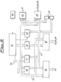
    • figure 2 is a schematic block diagram of the device;
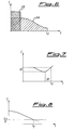
    • figures 3 to 8 are diagrams for illustrating the criteria for determining the accomplishment of a full charge process according to embodiments of the invention;
    • figure 9 is a block diagram of the logic module of an embodiment of the invention;
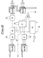
    • figure 10 is a block diagram of the analog module of an embodiment of the invention;
    • figure 11 is a block diagram of the power supply and control module of an embodiment of the invention;
    • figure 12 is a block diagram of the protection module of an embodiment of the invention;
    • figure 13 is a block diagram of the charge/discharge module of an embodiment of the invention; and
    • figure 14 is a block diagram of the external interface module of an embodiment of the invention;
    Figure 1 shows the main components that are mounted on the front panel of the battery treating device 1 according to the invention.
    The device 1 is supplied by an external power source (not shown) through the power supply connector 2. The feeding voltage is comprised in a range from 10 to 32 volts and preferably is 24 volts.
    This allows for the device being fed by the electric power from standard car batteries used by most vehicles.
    There are provided an on/off switch 3 for energizing the device 1, a pilot lamp 4 indicating the on condition of the device 1 and a fuse 5 for the protection against possible malfunctions in the power line.
    The device 1 is connected to a battery housing (not shown) through an output connector 6.
    In a preferred embodiment, the device 1 is equipped with four independent channels for simultaneously handling four batteries, even of different type from one another. To each of the four channels there is associated one of four two-position monostable switches 7a, 7b, 7c, 7d, one of a series of red LEDs 8a, 8b, 8c, 8d, and one of a series of green LEDs 9a, 9b, 9c, 9d. In one of the position each switch 7 causes the start of the treatment or its stop during the process, while in the other position each switch 7 causes an indication of the percentage of the battery charging over the corresponding channel to be displayed in alphanumeric form on a display 10.
    The red LEDs 8a-8d and the green LEDs 9a-9d are used for continuously indicating the process conditions of each channel.
    More particularly the permanent lighting of a LED 8 indicates either that a battery is connected to the associated channel, or that a battery is being discharged in a step of a revitalizing process; the LED is turned off either when a charging process is started by actuating the corresponding switch 7, or when a battery is being charged in a step of a revitalizing process. A flashing condition of a LED 8 indicates a malfunction in the corresponding channel.
    The permanent lighting of a LED 9 indicates that a treatment process is in progress in the corresponding channel, while the flashing condition of a LED 9 indicates that the process has been completed. In this case the device 1 maintains nevertheless a trickle charge in the corresponding channel until the process is stopped by acting on the corresponding switch 7.
    A three-position switch 11 is used to select one of the device functions: i.e a charge treatment, a revitalizing treatment or a general test of the device conditions and the batteries connected thereto.
    A similar three-position switch 12 is used to select one of the available charging rates, i.e. slow, standard, fast.
    A push-button 13 is provided for stopping acoustic and/or visual warning signals from the device in case of troubles or failures. By pushing such button, the operator acknowledges the warning and enables the device to show on the alphanumeric display 10 a code of the trouble or failure.
    In the preferred embodiment there is further provided a switch 14 for excluding any warning signal from the device without stopping the working thereof. This feature is particularly useful when it is desired to prevent the device from being located, e.g. in military applications when the device in being used during a mission requiring that enemy interception be prevented.
    Figure 2 shows a general block diagram of the device including an interconnecting board 20 to which the different modules of the device 1 are connected.
    More particularly there are provided: an external interface module 21 for handling the switching signals generated when the switches and push-buttons located on the device front panel are actuated (Figure 1), as well as for handling the warning signals on the front panel and any outwardly exchange of data through a serial interface of the RS-232 type; a module 22 for protecting both the device and the batteries against voltage swings or polarity reversal of the connected power source, as well as for filtering the input and output signals of the device; a power supply and control module 23 capable of supplying the voltages required for the device operation, as well as of checking the battery conditions; a microprocessor logic module 24 controlling both the battery treatment processes and the device functions; an analog module 25 for detecting and controlling the voltages and currents supplied to the batteries under charge; a charge/discharge module 26 for providing the charge/discharge sources for each channel.
    The revitalizing treatment subjects a battery to a series of charge and discharge cycles.
    In the preferred embodiment of the device there are provided from one to eight charge/discharge cycles, the first of which having a predetermined duration. More particularly the first charge process has a fixed duration of seven hours, whereas the subsequent ones are terminated in accordance with the standard methods for stopping the charge; the number of cycles is automatically determined by the device depending on the restored electric capacity at the end of each cycle.
    The device 1, through the logic module 24, accomplishes a constant-current or constant-voltage charge depending on the environment temperature and on the voltage across each battery.
    More particularly the charge process is first set at a constant current and it is so maintained till the voltage of the battery reaches the maximum allowed value, usually the one recommended by the manufacturer and being approximately in the range 1.6-1.7 volts. When the environment temperature is lower than a predetermined reference temperature, usually in the range from 0 °C to 5 °C, the device automatically switches to a constant-voltage charge.
    On the contrary, if the temperature is higher than said reference temperature, the device automatically switches to a constant-current charge condition, at a charging rate lower than the previous one, i.e. from "fast" to "standard", or from "standard" to "slow", when the voltage at the battery terminals reaches the maximum allowed value. When the current charging rate is already the minimum rate allowed by the device, i. e. the "slow" charging rate, the device automatically switches into a constant-voltage charge condition when the voltage at the battery terminals reaches again the maximum allowed value. By automatically performing the processes in accordance with the above illustrated modes, a high level of charging efficiency is maintained and possible damages to the batteries are prevented under any usage conditions.
    In case the charge is accomplished at a constant current value, the charging process is determined as completed when one of the following events takes place:
    • the product of the supplied current and the process time exceeds a predetermined value of the battery rated capacity Cn. This situation is schematically illustrated in the cartesian diagram I versus t (current v. time) in Figure 3, where the area of rectangle 30 is equal to the battery rated capacity Cn, whereas the area of rectangle 31 is representative of the current supplied to the battery from the start of the charging process to time tf when the process is stopped. In the preferred embodiment, the charging process is stopped when the product of the supplied current and the charge period exceeds about 1.3 the battery rated capacity Cn;
    • a voltage decrease at the battery terminals for a pre-determined time interval. This situation is schematically illustrated in the cartesian diagram V versus t (voltage v. time) in Figure 4 showing a part of the curve representing the voltage at the battery terminals as a function of the time. The charging process is stopped at time tf if the derivative of the voltage curve is negative, i.e. it exhibits a decrease ΔV in correspondence of a predetermined time interval Δt;
    • an increase of the voltage at the battery terminals that exceeds a predetermined value for a given time interval. This situation is schematically illustrated in the cartesian diagram V versus t (voltage v. time) in Figure 5 showing a part of the curve representing the voltage at the battery terminals as a function of the time. The charging process is stopped at time tf if the curve slope, i. e. the ratio between ΔV and Δt, exceeds a predetermined slope (e.g. that of the straight line 32) for a given time interval Δt.
    In case none of the above conditions is met, the charging process is nevertheless stopped after a given time interval to prevent possible damages to the battery. The maximum duration of a charge process changes as a function of the selected charge mode, that is fourteen hours for a "slow" charging process, five hours for a "standard" charging process, and two hours for a "fast" charging process.
    On the other hand, in a charge accomplished at a constant-voltage, the completion of the charging process is determined if one of the following events takes place:
    • the product of the supplied current and the process time exceeds a predetermined value of the battery rated capacity . This situation is schematically illustrated in the cartesian diagram I versus t (current v. time) in Figure 6 where the area of rectangle 33 is equal to the battery rated capacity Cn, whereas the area under the curve 34 is representative of the current supplied to the battery from the start of the process until the time tf when the process is stopped. Similarly to the case of the constant-current charge, the charging process is stopped when the product of the supplied current and the charging period exceeds about 1.3 the battery rated capacity Cn;
    • an increase of the charging current for a predetermined time interval depending on the selected charging mode. This situation is schematically illustrated in the cartesian diagram I versus t (current v. time) in Figure 7, showing a part of the curve representing the current supplied to the battery as a function of the time. The charging process is stopped at time tf if the curve of the supplied current shows an increase ΔI for a predetermined time interval Δt;
    • the charging current is lower than a predetermined fraction of the battery rated capacity. This situation is illustrated in the cartesian diagram I versus t (current v. time) in Figure 8 showing a part of the curve representing the current supplied as a function of the time. The charging process is stopped if the current intensity drops below a limit equal to the N-th fraction of the battery rated capacity Cn. In the preferred embodiment the value N=20 is selected.
    In this case too, if none of the above conditions is met, the charging process is nevertheless stopped after a predetermined time interval to prevent possible damages to the battery. However, in this case, the maximum duration of a charging process changes depending on the selected charging mode, that is twenty hours for a "slow" charging process, six hours and thirty minutes for a "standard" charging process, and three hours for a "fast" charging process.
    At the end of each charging process in accordance with the selected modes, the device 1 subjects the battery to a trickle charging step that preserves the battery charge conditions at the same time preventing any risk of overcharge and consequently of battery damages.
    The control and the execution of the different functions of the device 1 are carried out by the microprocessor logic module 24. More particularly, there are performed diagnostic tests in the device when power is turned on to detect possible malfunctions thereof, functions for automatically identifying the type, capacity and charging conditions of each battery, functions for detecting the conditions of open circuit, closed circuit and polarity reversal of each battery, functions for automatically selecting the modes and the charging rate for each battery in accordance with the conditions thereof and the temperature condition of the working environment, functions for automatically selecting the number of the charge and discharge cycles in the revitalizing process for each battery in accordance with its conditions, functions for monitoring the treatment processes to detect possible failures or malfunctions in the device or in the batteries, functions for determining the completion of the process for each battery and for maintaining a trickle charge condition, when the first condition is met, as well as functions for controlling said means for warning about events related to the working of the device and to the running processes.
    Figure 9 shows a block diagram of the logic module 24 in which a microprocessor 40 is provided that operates in accordance with a program stored in an EPROM memory unit 41. One or more RAM memory units 42 store the parameters of the batteries or those of predetermined battery arrangements. The values of these parameters can be modified by means of an external terminal connected to a standard RS-232 serial port (Figure 14), provided on the external interface module 21, and connected in turn to a port 43 of the USART type, for allowing the conversion of parallel bit patterns into corresponding serial streams. A clock device 44 sets the operating frequency of the microprocessor 40 and provides a time base to a timer 45. There is further provided a standby battery (not shown) connected to the RAM memory units, for maintaining the stored data when the external power source is off. The exchange of the command and/or control signals with the remaining modules of the device is achieved through a pair of parallel ports 46 and 47, a buffer 48 and a control device 49 controlling the asynchronous interruption conditions. More particularly the parallel port 46 is connected to the analog module 25, the parallel port 47 is connected to the power supply and control module 23, to the charge/discharge module 26 and to the analog module 25, the buffer 48 is connected to the external interface module 21, and the device 49 controlling the asynchronous interruption conditions to the external interface module 21, to the power supply and control module 23 and to the charge/discharge module 26.
    The connection between the units of the logic module 24 is accomplished through the bus lines 50, 51, for the address exchange, and a bus line 52 for the data exchange. An "address latch" device 53 allows for reading the addresses (less significant bits) on the line 51, and transferring them over the line 51 of the address bus.
    Figure 10 shows the block diagram of the analog module 25 including a twelve bit digital to analog converter 60, connected to the logic module 24, and a plurality of analog multiplexers allowing for the voltage measurement at the battery terminals, the measurement of the battery charge or discharge currents and the control of the battery charge current. More particularly it is provided a main multiplexer 61 for applying one of the four input voltage signals to a comparator 62. The input voltages of the main multiplexer 61 are a function of the process values (voltages and currents, either detected or supplied to the batteries), as well as of the environment temperature. The comparator 62 produces an output signal for the logic module 24 by comparing the signal from the main multiplexer 61 with a signal produced by the converter 60 on the basis of a reference signal 63.
    A multiplexer 64 selects one of the four output voltage signals from the current detecting units 65a-65d connected to the charge/discharge module 26. A polarity reversing device 66 is connected between the multiplexer 64 and the multiplexer 61, for reading the opposite polarity signal during the discharge processes.
    The reading of the output voltages from the charge/discharge module 26 is accomplished by units 68a-68d adapted to detect voltages in the four channels, whereas the selection of one of the four signals is achieved through a multiplexer 67.
    The connecting line 69 from the external interface module 21, carries a voltage signal representing the temperature of the environment in which processes are taking place.
    For controlling the charge and discharge currents in the four channels a demultiplexer device 70 is provided that applies the voltage signal from the converter 60 to one of the four voltage holding circuits 71a-71d. The voltages at the outputs of circuits 71a-71d are applied to the charge/discharge module 26 and to the circuits 72a-72d driving the MOSFET devices of said module 26.
    The input selection in the multiplexer devices 61, 64, 67 and the output selection in the demultiplexer 70, as well as the activation of the drive circuits 72a-72d are determined by the signals from the logic module 24.
    Figure 11 shows a block diagram of the power supply and control module 23. This latter includes a first converter 80 for converting the feed voltage rated at 24 volts d.c. from the drive and filter module 22 into a +15 volts d.c. and a -15 volts d.c. as requested for the battery treatment processes. Through a second converter 81 the 24 volts d.c. rated voltage is converted into a +5 volt d.c. voltage for the operation of the device 1.
    There are also provided four circuits 82a-82d for detecting possible short circuit and open circuit conditions of the batteries. Each circuit 82a-82d is actuated by a signal from the logic module 24 and sends back to the same module a binary signal indicating the state of the battery connected over the corresponding channel. Circuits 82a-82d drive corresponding relays in the protection module 22 for disconnecting a battery in case of a malfunction thereof.
    Figure 12 reproduces a block diagram of the protection and filtering module 22. In the scheme there are shown the already mentioned battery protection relays labelled as 90a-90d. A series of devices 93a-93d protect the batteries against possible polarity reversal.
    It further includes a relay 91 for protecting the device over the feeding line from the connector 2, to which the external power source is connected. The relay 91 is driven by a circuit 92 for the protection against possible peaks of the feed voltage at switching on.
    The module 22 further includes the filters required to meet the interference requirements for the device 1 (EMI standards). Thus a filter 94 is provided in the 24 volt d.c. supply line connected to the power supply and control module 23, as well as four filters 95a-95d on the connection lines of the corresponding channels that lead to the connector 6 (Figure 1) on the front panel.
    Figure 13 shows the block diagram of the battery charge/discharge module 26. This module includes the devices 100a-100d of the MOSFET type for discharging the batteries in the revitalizing processes, the circuits 101a-101d for sensing the battery currents, as well as a series of circuits and devices for monitoring the charge voltages and currents. More particularly they comprise four voltage-programmed drive circuits 102a-102d for the power supplied by the devices 103a-103d of the MOSFET type. These latter are serially connected transformer devices 104a-104d, rectifier devices 105a-105d and filtering devices 106a-106d for realizing the current sources with a limited power dissipation in the typical configurations of switching power supplies. There are further provided current limiting devices 107a-107d with a feedback connection between the MOSFET devices 103a-103d and the corresponding drive circuits 102a-102d, as well as voltage limiting devices 108a-108d with a feed-back connection between the filtering devices 106a-106d and the drive circuits 102a-102d. The limiting devices allow for keeping the voltage and current levels within the safety ranges to prevent battery damages.
    Figure 14 shows the block diagram of the external interface module 21, that is the module that constitutes the interface between the operator and the microprocessor 40. The module 21 comprises a unit 100 of the "buffer latch" type for connecting the switching and signalling devices on the front panel (Figure 1). More particularly the connections concern the four switches 7a-7d for starting and stopping the process over the channels, the switch 12 for selecting one of the charging rates, the push-button 13 for acknowledging the alarm signals and stopping the warning signals, the switch 14 for excluding the external signals without interruption of the device 1, as well as the LEDs 8a-8d, 9a-9d. The device 110 is also connected to a decoder circuit 111 for identifying the type of the battery housing and the bus line 114 carrying data from the buffer 48 of the logic module 24 to the display 10. The switch 3 for turning on the device 1, although included in module 21, is directly connected to the protection and filtering module 22.
    Additional connections to the logic module 24 comprise a serial line 115 for data transferring through an interface 112 of the RS-232 type, and a lead for energizing an acoustic signalling device 113.
    A temperature transducer 116 connected to an amplifier 117 provides the analog module 25 with a voltage value representative of the temperature of the environment in which the device is working.

    Claims (14)

    1. A device for charging or revitalizing one or more batteries at the same time, comprising:
      a plurality of independent channels to connect each battery to the device;
      a power supply and control module (23) adapted to supply the device with the necessary voltages for the working thereof, and to control battery protection means;
      a module (22) for protecting the device and the batteries being charged against voltage changes or polarity reversal, as well as for filtering the input and output signals of the device;
      a charge/discharge module (26) to provide the charge/discharge sources for each channel;
      a microprocessor logic module (24) for controlling both the treatment processes to which said batteries are subjected and the device functions, said processes being carried out for each channel in a manner not depending on the characteristics of the rated capacity, the charging conditions and the treatment selected for the other channels, said microprocessor logic module including means (41) for storing control programs and means (42) for storing parameters related to the processes in progress;
      an analog module (25) for detecting and controlling the voltages and currents supplied to the batteries; and
      an external interface module (21) comprising means (7a, 7b, 7c, 7d) for manually starting and stopping a treatment process in each channel, means (11) for selecting the kind of treatment each battery has to be subjected to, means (12) for selecting the mode of each process, as well as means for displaying the occurrence of certain events related to the working of the device, to the process execution and the battery conditions,
      characterized in that it provides a constant-current charge and an automatic switching to a constant-voltage charge when the voltage of the battery terminals reaches a maximum allowable value and the environment temperature is lower than a predetermined reference temperature,
      and an automatic switching, from the constant-current charge, to a constant-current charge at a rate lower than the previous one when the voltage of the battery terminals reaches the maximum value and the environment temperature is higher than the predetermined reference value.
    2. A device as claimed in claim 1, characterized in that said reference temperature is within the range from 0 °C to +5 °C.
    3. A device as claimed in claim 1, characterized in that said logic module (24) is adapted to determine the completion of the charging process when:
      either the product of the supplied current and the process time exceeds a predetermined value of the battery rated capacity; or
      a voltage decrease occurs at the battery terminals for a pre-determined time interval; or
      an increase of the voltage at the battery terminals exceeds a predetermined value for a given time interval; or
      if none of the above conditions is met, the duration of the charging process exceeds a predetermined time depending on the selected charging mode.
    4. A device as claimed in claims 1 to 3, characterized in that said logic module (24) is adapted to determine the completion of the charging process for each battery, when:
      either the product of the supplied current and the process time exceeds a predetermined value of the battery rated capacity; or
      the charging current increases for a predetermined time interval depending on the selected charging mode; or
      the charging current is lower than a predetermined fraction of the battery rated capacity; or when
      in case none of the above conditions has been met, the duration of the charging process exceeds a prefixed time depending on the selected charging mode.
    5. A device as claimed in claims 3 or 4, characterized in that it provides a pulsed charging step at the end of each charging or revitalizing treatment.
    6. A device as claimed in claim 1, characterized in that said protection module (22) comprises a plurality of relays (90a-90d) controlled by circuits (93a-93d) provided in said feed module.
    7. A device as claimed in claim 1, characterized in that said charge/discharge module (26) comprises power sources (102-108) adapted to reduce the power dissipation and devices (100a-100d) of the MOSFET type for discharging the batteries during the revitalizing treatments.
    8. A device as claimed in claim 1, characterized in that said storing means in said microprocessor logic module (24) comprises an EPROM memory unit (41) for storing control programs and one or more RAM memory units (42) a for storing the parameters related to the running processes.
    9. A device as claimed in claim 8, characterized in that said external interface module (21) comprises an RS-232 serial line (115) connected to a port (43) of the USART type in said logic module (24) to allow the connection with external peripheral devices adapted to store in said RAM memory (42) a plurality of parameters related to different battery arrangements.
    10. A device as claimed in claim 8, characterized in that it provides a standby battery associated to said RAM memory units (42) for maintaining the stored data when the external power source is off.
    11. A device as claimed in claim 1, characterized in that said analog module (25) comprises a twelve bit digital to analog converter (60) and a plurality of analog multiplexing devices (61, 64, 67, 70) to allow the measurement of the battery terminal voltage, the measurement of the charging or discharging battery current, and the control of the battery charging current.
    12. A device as claimed in claim 1, characterized by a display means (8a-8d, 9a-9d) comprising an eight character alphanumeric display and a pair of LEDs for each channel.
    13. A device as claimed in any of the preceding claims, characterized in that it comprises at least four of said channels.
    14. Use of device as recited by any preceding claim in carrying out the charging or the simultaneous revitalizing of a plurality of sealed Ni-Cd batteries.
    EP93830259A 1993-06-10 1993-06-10 Device for making the charge and revitalization treatment of batteries Expired - Lifetime EP0629032B1 (en)

    Priority Applications (2)

    Application Number Priority Date Filing Date Title
    EP93830259A EP0629032B1 (en) 1993-06-10 1993-06-10 Device for making the charge and revitalization treatment of batteries
    CA002108313A CA2108313A1 (en) 1993-06-10 1993-10-13 Device for making the charge and revitalization treatment of batteries

    Applications Claiming Priority (1)

    Application Number Priority Date Filing Date Title
    EP93830259A EP0629032B1 (en) 1993-06-10 1993-06-10 Device for making the charge and revitalization treatment of batteries

    Publications (2)

    Publication Number Publication Date
    EP0629032A1 EP0629032A1 (en) 1994-12-14
    EP0629032B1 true EP0629032B1 (en) 1998-03-25

    Family

    ID=8215181

    Family Applications (1)

    Application Number Title Priority Date Filing Date
    EP93830259A Expired - Lifetime EP0629032B1 (en) 1993-06-10 1993-06-10 Device for making the charge and revitalization treatment of batteries

    Country Status (2)

    Country Link
    EP (1) EP0629032B1 (en)
    CA (1) CA2108313A1 (en)

    Families Citing this family (7)

    * Cited by examiner, † Cited by third party
    Publication number Priority date Publication date Assignee Title
    AU4674196A (en) * 1995-02-07 1996-08-27 Benchmarq Microelectronics, Inc. Lead acid charger
    FR2730358B1 (en) * 1995-02-08 1997-04-11 Leclanche Sa QUICK CHARGING METHOD FOR WATERPROOF BATTERIES
    FR2739724B1 (en) * 1995-10-05 1997-11-14 Accumulateurs Fixes METHOD FOR CHARGING WATERPROOF NICKEL-CADMIUM BATTERIES
    US5896024A (en) * 1998-03-24 1999-04-20 Black & Decker, Inc. Method and apparatus for manually selecting battery charging process
    DE19847988A1 (en) * 1998-10-17 2000-04-27 Norbert Fiedler System for automatic charging of rechargeable galvanic elements with fixed and liquid electrolytes
    US7468596B2 (en) 2004-11-18 2008-12-23 Jeckson Electric Company Limited Battery charger for various sizes of batteries with selection of appropriate charging power
    ES2274698A1 (en) * 2005-06-20 2007-05-16 Tecnica Electronica De Automatismo Y Medida, S.A. Monitoring system for batteries and supercapacitors especially for variable speed aerogenerators, includes real-time measurement of the voltage and current of the batteries and supercapacitors as well as the temperature of their housing

    Family Cites Families (6)

    * Cited by examiner, † Cited by third party
    Publication number Priority date Publication date Assignee Title
    DE3700092A1 (en) * 1987-01-03 1988-07-14 Roland Mueller Device for simultaneously charging a plurality of accumulators (rechargeable batteries)
    DE3834004A1 (en) * 1988-10-06 1990-04-12 Nortec Electronic Dr Juergen R Charger and discharger for charging and for servicing rechargeable batteries, and the use of the charger and discharger
    SE465053B (en) * 1988-11-25 1991-07-15 Folke Bertil Mattsson METHOD AND DEVICE FOR FAST CHARGING OF ACCUMULATOR BATTERIES
    AT396637B (en) * 1990-07-23 1993-10-25 Industrieelektronik Poelz CHARGER BATTERY CHARGER
    US5365160A (en) * 1991-09-06 1994-11-15 Telxon Corporation Apparatus and method for charging batteries
    US5218286A (en) * 1991-09-16 1993-06-08 Monarch Marking Systems, Inc. Multichannel battery charger

    Also Published As

    Publication number Publication date
    CA2108313A1 (en) 1994-12-11
    EP0629032A1 (en) 1994-12-14

    Similar Documents

    Publication Publication Date Title
    US4302714A (en) Rechargeable battery charger system for charging testing, rejuvenation and preventative maintenance
    US7525280B2 (en) Multi-type battery charger control
    EP1131646B1 (en) Battery power source protecting device for an electromotive device
    EP0771487B1 (en) A method and apparatus for processing batteries
    US5757163A (en) Battery Charger and method for simultaneously charging multiple batteries from a single power supply
    GB2219151A (en) Battery charging
    JPH0898414A (en) Intelligent battery device,its operating method and electricapparatus
    US4413220A (en) Battery discharge rate control circuitry
    EP0629032B1 (en) Device for making the charge and revitalization treatment of batteries
    US5013992A (en) Microprocessor controlled battery charger
    JP2011029010A (en) Lithium ion secondary battery system and power supply method to management device
    EP0335316A2 (en) Apparatus for controlling selection of batteries
    US5486750A (en) Battery charger with polarity sensing and timer
    JPH07203634A (en) Charger for secondary cell
    CN101577441A (en) Apparatus and method for controlling power
    JPH03173323A (en) Secondary battery charger
    RU2183887C2 (en) Method for charging storage battery and computer-aided system for implementing it
    JPH09294338A (en) Battery apparatus
    JPH02119069A (en) Battery checker
    KR100219776B1 (en) Charger of storage battery
    JPH10285816A (en) Method and equipment for constant-current and constant-voltage charging
    KR200377803Y1 (en) Integrated battery charger for field operations
    JPH0491630A (en) Power source
    KR0124555Y1 (en) Battery charging/discharging apparatus using a computer
    EP0450145B1 (en) Method and apparatus for battery control

    Legal Events

    Date Code Title Description
    PUAI Public reference made under article 153(3) epc to a published international application that has entered the european phase

    Free format text: ORIGINAL CODE: 0009012

    17P Request for examination filed

    Effective date: 19940616

    AK Designated contracting states

    Kind code of ref document: A1

    Designated state(s): BE ES FR GB IT NL

    17Q First examination report despatched

    Effective date: 19960705

    GRAG Despatch of communication of intention to grant

    Free format text: ORIGINAL CODE: EPIDOS AGRA

    GRAG Despatch of communication of intention to grant

    Free format text: ORIGINAL CODE: EPIDOS AGRA

    GRAH Despatch of communication of intention to grant a patent

    Free format text: ORIGINAL CODE: EPIDOS IGRA

    GRAH Despatch of communication of intention to grant a patent

    Free format text: ORIGINAL CODE: EPIDOS IGRA

    GRAA (expected) grant

    Free format text: ORIGINAL CODE: 0009210

    AK Designated contracting states

    Kind code of ref document: B1

    Designated state(s): BE ES FR GB IT NL

    PG25 Lapsed in a contracting state [announced via postgrant information from national office to epo]

    Ref country code: NL

    Free format text: LAPSE BECAUSE OF FAILURE TO SUBMIT A TRANSLATION OF THE DESCRIPTION OR TO PAY THE FEE WITHIN THE PRESCRIBED TIME-LIMIT

    Effective date: 19980325

    Ref country code: FR

    Free format text: LAPSE BECAUSE OF FAILURE TO SUBMIT A TRANSLATION OF THE DESCRIPTION OR TO PAY THE FEE WITHIN THE PRESCRIBED TIME-LIMIT

    Effective date: 19980325

    Ref country code: ES

    Free format text: THE PATENT HAS BEEN ANNULLED BY A DECISION OF A NATIONAL AUTHORITY

    Effective date: 19980325

    Ref country code: BE

    Free format text: LAPSE BECAUSE OF FAILURE TO SUBMIT A TRANSLATION OF THE DESCRIPTION OR TO PAY THE FEE WITHIN THE PRESCRIBED TIME-LIMIT

    Effective date: 19980325

    ITF It: translation for a ep patent filed

    Owner name: STUDIO CIONI & PIPPARELLI

    PG25 Lapsed in a contracting state [announced via postgrant information from national office to epo]

    Ref country code: GB

    Free format text: LAPSE BECAUSE OF NON-PAYMENT OF DUE FEES

    Effective date: 19980625

    EN Fr: translation not filed
    NLV1 Nl: lapsed or annulled due to failure to fulfill the requirements of art. 29p and 29m of the patents act
    PLBE No opposition filed within time limit

    Free format text: ORIGINAL CODE: 0009261

    STAA Information on the status of an ep patent application or granted ep patent

    Free format text: STATUS: NO OPPOSITION FILED WITHIN TIME LIMIT

    GBPC Gb: european patent ceased through non-payment of renewal fee

    Effective date: 19980625

    26N No opposition filed
    PGFP Annual fee paid to national office [announced via postgrant information from national office to epo]

    Ref country code: IT

    Payment date: 20060630

    Year of fee payment: 14

    PG25 Lapsed in a contracting state [announced via postgrant information from national office to epo]

    Ref country code: IT

    Free format text: LAPSE BECAUSE OF NON-PAYMENT OF DUE FEES

    Effective date: 20070610