EP0628399B1 - Verfahren zur Herstellung eines rohrförmigen Hohlkörpers - Google Patents
Verfahren zur Herstellung eines rohrförmigen Hohlkörpers Download PDFInfo
- Publication number
- EP0628399B1 EP0628399B1 EP19940810269 EP94810269A EP0628399B1 EP 0628399 B1 EP0628399 B1 EP 0628399B1 EP 19940810269 EP19940810269 EP 19940810269 EP 94810269 A EP94810269 A EP 94810269A EP 0628399 B1 EP0628399 B1 EP 0628399B1
- Authority
- EP
- European Patent Office
- Prior art keywords
- welding
- metal strip
- plastic
- mandrel
- overlap
- Prior art date
- Legal status (The legal status is an assumption and is not a legal conclusion. Google has not performed a legal analysis and makes no representation as to the accuracy of the status listed.)
- Expired - Lifetime
Links
Images

Classifications
-
- B—PERFORMING OPERATIONS; TRANSPORTING
- B29—WORKING OF PLASTICS; WORKING OF SUBSTANCES IN A PLASTIC STATE IN GENERAL
- B29C—SHAPING OR JOINING OF PLASTICS; SHAPING OF MATERIAL IN A PLASTIC STATE, NOT OTHERWISE PROVIDED FOR; AFTER-TREATMENT OF THE SHAPED PRODUCTS, e.g. REPAIRING
- B29C65/00—Joining or sealing of preformed parts, e.g. welding of plastics materials; Apparatus therefor
- B29C65/02—Joining or sealing of preformed parts, e.g. welding of plastics materials; Apparatus therefor by heating, with or without pressure
- B29C65/18—Joining or sealing of preformed parts, e.g. welding of plastics materials; Apparatus therefor by heating, with or without pressure using heated tools
- B29C65/24—Joining or sealing of preformed parts, e.g. welding of plastics materials; Apparatus therefor by heating, with or without pressure using heated tools characterised by the means for heating the tool
- B29C65/30—Electrical means
- B29C65/32—Induction
-
- B—PERFORMING OPERATIONS; TRANSPORTING
- B29—WORKING OF PLASTICS; WORKING OF SUBSTANCES IN A PLASTIC STATE IN GENERAL
- B29C—SHAPING OR JOINING OF PLASTICS; SHAPING OF MATERIAL IN A PLASTIC STATE, NOT OTHERWISE PROVIDED FOR; AFTER-TREATMENT OF THE SHAPED PRODUCTS, e.g. REPAIRING
- B29C53/00—Shaping by bending, folding, twisting, straightening or flattening; Apparatus therefor
- B29C53/36—Bending and joining, e.g. for making hollow articles
- B29C53/38—Bending and joining, e.g. for making hollow articles by bending sheets or strips at right angles to the longitudinal axis of the article being formed and joining the edges
- B29C53/40—Bending and joining, e.g. for making hollow articles by bending sheets or strips at right angles to the longitudinal axis of the article being formed and joining the edges for articles of definite length, i.e. discrete articles
- B29C53/42—Bending and joining, e.g. for making hollow articles by bending sheets or strips at right angles to the longitudinal axis of the article being formed and joining the edges for articles of definite length, i.e. discrete articles using internal forming surfaces, e.g. mandrels
-
- B—PERFORMING OPERATIONS; TRANSPORTING
- B29—WORKING OF PLASTICS; WORKING OF SUBSTANCES IN A PLASTIC STATE IN GENERAL
- B29C—SHAPING OR JOINING OF PLASTICS; SHAPING OF MATERIAL IN A PLASTIC STATE, NOT OTHERWISE PROVIDED FOR; AFTER-TREATMENT OF THE SHAPED PRODUCTS, e.g. REPAIRING
- B29C65/00—Joining or sealing of preformed parts, e.g. welding of plastics materials; Apparatus therefor
- B29C65/02—Joining or sealing of preformed parts, e.g. welding of plastics materials; Apparatus therefor by heating, with or without pressure
- B29C65/18—Joining or sealing of preformed parts, e.g. welding of plastics materials; Apparatus therefor by heating, with or without pressure using heated tools
-
- B—PERFORMING OPERATIONS; TRANSPORTING
- B29—WORKING OF PLASTICS; WORKING OF SUBSTANCES IN A PLASTIC STATE IN GENERAL
- B29C—SHAPING OR JOINING OF PLASTICS; SHAPING OF MATERIAL IN A PLASTIC STATE, NOT OTHERWISE PROVIDED FOR; AFTER-TREATMENT OF THE SHAPED PRODUCTS, e.g. REPAIRING
- B29C66/00—General aspects of processes or apparatus for joining preformed parts
- B29C66/01—General aspects dealing with the joint area or with the area to be joined
- B29C66/05—Particular design of joint configurations
- B29C66/10—Particular design of joint configurations particular design of the joint cross-sections
- B29C66/11—Joint cross-sections comprising a single joint-segment, i.e. one of the parts to be joined comprising a single joint-segment in the joint cross-section
- B29C66/112—Single lapped joints
- B29C66/1122—Single lap to lap joints, i.e. overlap joints
-
- B—PERFORMING OPERATIONS; TRANSPORTING
- B29—WORKING OF PLASTICS; WORKING OF SUBSTANCES IN A PLASTIC STATE IN GENERAL
- B29C—SHAPING OR JOINING OF PLASTICS; SHAPING OF MATERIAL IN A PLASTIC STATE, NOT OTHERWISE PROVIDED FOR; AFTER-TREATMENT OF THE SHAPED PRODUCTS, e.g. REPAIRING
- B29C66/00—General aspects of processes or apparatus for joining preformed parts
- B29C66/40—General aspects of joining substantially flat articles, e.g. plates, sheets or web-like materials; Making flat seams in tubular or hollow articles; Joining single elements to substantially flat surfaces
- B29C66/41—Joining substantially flat articles ; Making flat seams in tubular or hollow articles
- B29C66/43—Joining a relatively small portion of the surface of said articles
- B29C66/432—Joining a relatively small portion of the surface of said articles for making tubular articles or closed loops, e.g. by joining several sheets ; for making hollow articles or hollow preforms
- B29C66/4322—Joining a relatively small portion of the surface of said articles for making tubular articles or closed loops, e.g. by joining several sheets ; for making hollow articles or hollow preforms by joining a single sheet to itself
-
- B—PERFORMING OPERATIONS; TRANSPORTING
- B29—WORKING OF PLASTICS; WORKING OF SUBSTANCES IN A PLASTIC STATE IN GENERAL
- B29C—SHAPING OR JOINING OF PLASTICS; SHAPING OF MATERIAL IN A PLASTIC STATE, NOT OTHERWISE PROVIDED FOR; AFTER-TREATMENT OF THE SHAPED PRODUCTS, e.g. REPAIRING
- B29C66/00—General aspects of processes or apparatus for joining preformed parts
- B29C66/40—General aspects of joining substantially flat articles, e.g. plates, sheets or web-like materials; Making flat seams in tubular or hollow articles; Joining single elements to substantially flat surfaces
- B29C66/49—Internally supporting the, e.g. tubular, article during joining
-
- B—PERFORMING OPERATIONS; TRANSPORTING
- B29—WORKING OF PLASTICS; WORKING OF SUBSTANCES IN A PLASTIC STATE IN GENERAL
- B29C—SHAPING OR JOINING OF PLASTICS; SHAPING OF MATERIAL IN A PLASTIC STATE, NOT OTHERWISE PROVIDED FOR; AFTER-TREATMENT OF THE SHAPED PRODUCTS, e.g. REPAIRING
- B29C66/00—General aspects of processes or apparatus for joining preformed parts
- B29C66/70—General aspects of processes or apparatus for joining preformed parts characterised by the composition, physical properties or the structure of the material of the parts to be joined; Joining with non-plastics material
- B29C66/72—General aspects of processes or apparatus for joining preformed parts characterised by the composition, physical properties or the structure of the material of the parts to be joined; Joining with non-plastics material characterised by the structure of the material of the parts to be joined
- B29C66/723—General aspects of processes or apparatus for joining preformed parts characterised by the composition, physical properties or the structure of the material of the parts to be joined; Joining with non-plastics material characterised by the structure of the material of the parts to be joined being multi-layered
- B29C66/7232—General aspects of processes or apparatus for joining preformed parts characterised by the composition, physical properties or the structure of the material of the parts to be joined; Joining with non-plastics material characterised by the structure of the material of the parts to be joined being multi-layered comprising a non-plastics layer
- B29C66/72321—General aspects of processes or apparatus for joining preformed parts characterised by the composition, physical properties or the structure of the material of the parts to be joined; Joining with non-plastics material characterised by the structure of the material of the parts to be joined being multi-layered comprising a non-plastics layer consisting of metals or their alloys
-
- B—PERFORMING OPERATIONS; TRANSPORTING
- B29—WORKING OF PLASTICS; WORKING OF SUBSTANCES IN A PLASTIC STATE IN GENERAL
- B29C—SHAPING OR JOINING OF PLASTICS; SHAPING OF MATERIAL IN A PLASTIC STATE, NOT OTHERWISE PROVIDED FOR; AFTER-TREATMENT OF THE SHAPED PRODUCTS, e.g. REPAIRING
- B29C66/00—General aspects of processes or apparatus for joining preformed parts
- B29C66/70—General aspects of processes or apparatus for joining preformed parts characterised by the composition, physical properties or the structure of the material of the parts to be joined; Joining with non-plastics material
- B29C66/72—General aspects of processes or apparatus for joining preformed parts characterised by the composition, physical properties or the structure of the material of the parts to be joined; Joining with non-plastics material characterised by the structure of the material of the parts to be joined
- B29C66/723—General aspects of processes or apparatus for joining preformed parts characterised by the composition, physical properties or the structure of the material of the parts to be joined; Joining with non-plastics material characterised by the structure of the material of the parts to be joined being multi-layered
- B29C66/7234—General aspects of processes or apparatus for joining preformed parts characterised by the composition, physical properties or the structure of the material of the parts to be joined; Joining with non-plastics material characterised by the structure of the material of the parts to be joined being multi-layered comprising a barrier layer
-
- B—PERFORMING OPERATIONS; TRANSPORTING
- B29—WORKING OF PLASTICS; WORKING OF SUBSTANCES IN A PLASTIC STATE IN GENERAL
- B29C—SHAPING OR JOINING OF PLASTICS; SHAPING OF MATERIAL IN A PLASTIC STATE, NOT OTHERWISE PROVIDED FOR; AFTER-TREATMENT OF THE SHAPED PRODUCTS, e.g. REPAIRING
- B29C66/00—General aspects of processes or apparatus for joining preformed parts
- B29C66/80—General aspects of machine operations or constructions and parts thereof
- B29C66/81—General aspects of the pressing elements, i.e. the elements applying pressure on the parts to be joined in the area to be joined, e.g. the welding jaws or clamps
- B29C66/816—General aspects of the pressing elements, i.e. the elements applying pressure on the parts to be joined in the area to be joined, e.g. the welding jaws or clamps characterised by the mounting of the pressing elements, e.g. of the welding jaws or clamps
- B29C66/8161—General aspects of the pressing elements, i.e. the elements applying pressure on the parts to be joined in the area to be joined, e.g. the welding jaws or clamps characterised by the mounting of the pressing elements, e.g. of the welding jaws or clamps said pressing elements being supported or backed-up by springs or by resilient material
-
- B—PERFORMING OPERATIONS; TRANSPORTING
- B29—WORKING OF PLASTICS; WORKING OF SUBSTANCES IN A PLASTIC STATE IN GENERAL
- B29C—SHAPING OR JOINING OF PLASTICS; SHAPING OF MATERIAL IN A PLASTIC STATE, NOT OTHERWISE PROVIDED FOR; AFTER-TREATMENT OF THE SHAPED PRODUCTS, e.g. REPAIRING
- B29C66/00—General aspects of processes or apparatus for joining preformed parts
- B29C66/80—General aspects of machine operations or constructions and parts thereof
- B29C66/81—General aspects of the pressing elements, i.e. the elements applying pressure on the parts to be joined in the area to be joined, e.g. the welding jaws or clamps
- B29C66/818—General aspects of the pressing elements, i.e. the elements applying pressure on the parts to be joined in the area to be joined, e.g. the welding jaws or clamps characterised by the cooling constructional aspects, or by the thermal or electrical insulating or conducting constructional aspects of the welding jaws or of the clamps ; comprising means for compensating for the thermal expansion of the welding jaws or of the clamps
- B29C66/8181—General aspects of the pressing elements, i.e. the elements applying pressure on the parts to be joined in the area to be joined, e.g. the welding jaws or clamps characterised by the cooling constructional aspects, or by the thermal or electrical insulating or conducting constructional aspects of the welding jaws or of the clamps ; comprising means for compensating for the thermal expansion of the welding jaws or of the clamps characterised by the cooling constructional aspects
- B29C66/81811—General aspects of the pressing elements, i.e. the elements applying pressure on the parts to be joined in the area to be joined, e.g. the welding jaws or clamps characterised by the cooling constructional aspects, or by the thermal or electrical insulating or conducting constructional aspects of the welding jaws or of the clamps ; comprising means for compensating for the thermal expansion of the welding jaws or of the clamps characterised by the cooling constructional aspects of the welding jaws
-
- B—PERFORMING OPERATIONS; TRANSPORTING
- B29—WORKING OF PLASTICS; WORKING OF SUBSTANCES IN A PLASTIC STATE IN GENERAL
- B29C—SHAPING OR JOINING OF PLASTICS; SHAPING OF MATERIAL IN A PLASTIC STATE, NOT OTHERWISE PROVIDED FOR; AFTER-TREATMENT OF THE SHAPED PRODUCTS, e.g. REPAIRING
- B29C66/00—General aspects of processes or apparatus for joining preformed parts
- B29C66/80—General aspects of machine operations or constructions and parts thereof
- B29C66/83—General aspects of machine operations or constructions and parts thereof characterised by the movement of the joining or pressing tools
- B29C66/832—Reciprocating joining or pressing tools
- B29C66/8322—Joining or pressing tools reciprocating along one axis
-
- B—PERFORMING OPERATIONS; TRANSPORTING
- B29—WORKING OF PLASTICS; WORKING OF SUBSTANCES IN A PLASTIC STATE IN GENERAL
- B29C—SHAPING OR JOINING OF PLASTICS; SHAPING OF MATERIAL IN A PLASTIC STATE, NOT OTHERWISE PROVIDED FOR; AFTER-TREATMENT OF THE SHAPED PRODUCTS, e.g. REPAIRING
- B29C66/00—General aspects of processes or apparatus for joining preformed parts
- B29C66/90—Measuring or controlling the joining process
- B29C66/91—Measuring or controlling the joining process by measuring or controlling the temperature, the heat or the thermal flux
- B29C66/914—Measuring or controlling the joining process by measuring or controlling the temperature, the heat or the thermal flux by controlling or regulating the temperature, the heat or the thermal flux
- B29C66/9141—Measuring or controlling the joining process by measuring or controlling the temperature, the heat or the thermal flux by controlling or regulating the temperature, the heat or the thermal flux by controlling or regulating the temperature
- B29C66/91421—Measuring or controlling the joining process by measuring or controlling the temperature, the heat or the thermal flux by controlling or regulating the temperature, the heat or the thermal flux by controlling or regulating the temperature of the joining tools
- B29C66/91423—Measuring or controlling the joining process by measuring or controlling the temperature, the heat or the thermal flux by controlling or regulating the temperature, the heat or the thermal flux by controlling or regulating the temperature of the joining tools using joining tools having different temperature zones or using several joining tools with different temperatures
-
- B—PERFORMING OPERATIONS; TRANSPORTING
- B29—WORKING OF PLASTICS; WORKING OF SUBSTANCES IN A PLASTIC STATE IN GENERAL
- B29C—SHAPING OR JOINING OF PLASTICS; SHAPING OF MATERIAL IN A PLASTIC STATE, NOT OTHERWISE PROVIDED FOR; AFTER-TREATMENT OF THE SHAPED PRODUCTS, e.g. REPAIRING
- B29C66/00—General aspects of processes or apparatus for joining preformed parts
- B29C66/01—General aspects dealing with the joint area or with the area to be joined
- B29C66/349—Cooling the welding zone on the welding spot
- B29C66/3492—Cooling the welding zone on the welding spot by means placed on the side opposed to the welding tool
-
- B—PERFORMING OPERATIONS; TRANSPORTING
- B29—WORKING OF PLASTICS; WORKING OF SUBSTANCES IN A PLASTIC STATE IN GENERAL
- B29C—SHAPING OR JOINING OF PLASTICS; SHAPING OF MATERIAL IN A PLASTIC STATE, NOT OTHERWISE PROVIDED FOR; AFTER-TREATMENT OF THE SHAPED PRODUCTS, e.g. REPAIRING
- B29C66/00—General aspects of processes or apparatus for joining preformed parts
- B29C66/70—General aspects of processes or apparatus for joining preformed parts characterised by the composition, physical properties or the structure of the material of the parts to be joined; Joining with non-plastics material
- B29C66/71—General aspects of processes or apparatus for joining preformed parts characterised by the composition, physical properties or the structure of the material of the parts to be joined; Joining with non-plastics material characterised by the composition of the plastics material of the parts to be joined
-
- B—PERFORMING OPERATIONS; TRANSPORTING
- B29—WORKING OF PLASTICS; WORKING OF SUBSTANCES IN A PLASTIC STATE IN GENERAL
- B29C—SHAPING OR JOINING OF PLASTICS; SHAPING OF MATERIAL IN A PLASTIC STATE, NOT OTHERWISE PROVIDED FOR; AFTER-TREATMENT OF THE SHAPED PRODUCTS, e.g. REPAIRING
- B29C66/00—General aspects of processes or apparatus for joining preformed parts
- B29C66/70—General aspects of processes or apparatus for joining preformed parts characterised by the composition, physical properties or the structure of the material of the parts to be joined; Joining with non-plastics material
- B29C66/72—General aspects of processes or apparatus for joining preformed parts characterised by the composition, physical properties or the structure of the material of the parts to be joined; Joining with non-plastics material characterised by the structure of the material of the parts to be joined
- B29C66/723—General aspects of processes or apparatus for joining preformed parts characterised by the composition, physical properties or the structure of the material of the parts to be joined; Joining with non-plastics material characterised by the structure of the material of the parts to be joined being multi-layered
- B29C66/7232—General aspects of processes or apparatus for joining preformed parts characterised by the composition, physical properties or the structure of the material of the parts to be joined; Joining with non-plastics material characterised by the structure of the material of the parts to be joined being multi-layered comprising a non-plastics layer
- B29C66/72324—General aspects of processes or apparatus for joining preformed parts characterised by the composition, physical properties or the structure of the material of the parts to be joined; Joining with non-plastics material characterised by the structure of the material of the parts to be joined being multi-layered comprising a non-plastics layer consisting of inorganic materials not provided for in B29C66/72321 - B29C66/72322
- B29C66/72325—Ceramics
-
- B—PERFORMING OPERATIONS; TRANSPORTING
- B29—WORKING OF PLASTICS; WORKING OF SUBSTANCES IN A PLASTIC STATE IN GENERAL
- B29L—INDEXING SCHEME ASSOCIATED WITH SUBCLASS B29C, RELATING TO PARTICULAR ARTICLES
- B29L2009/00—Layered products
-
- B—PERFORMING OPERATIONS; TRANSPORTING
- B29—WORKING OF PLASTICS; WORKING OF SUBSTANCES IN A PLASTIC STATE IN GENERAL
- B29L—INDEXING SCHEME ASSOCIATED WITH SUBCLASS B29C, RELATING TO PARTICULAR ARTICLES
- B29L2023/00—Tubular articles
Definitions
- the invention relates to a method for producing a tubular hollow body according to the preamble of claim 1.
- Tubular body or pipe pieces for packaging containers thermoplastic films with metallic barrier layer, packaging tubes in particular are - among others in the Unrelated to the present invention
- Manufacturing methods - by reshaping one first lay a flat film into a tube, overlay two opposite film edge sections to an overlap area with subsequent Welding the film edge sections to a longitudinal weld.
- This procedure is known to practice in two variants, namely in a discontinuous and a continuous process. In which discontinuous process is handled by one a blank corresponding to a tubular body, it So single tube body are manufactured, while in the continuous process from a running film strip an "endless tubular body" is formed, which corresponds to the desired tube body length is isolated.
- the invention as discussed below, this applies discontinuously ongoing procedures.
- the welding takes place by heat and pressure, by a welding cooling jaw the overlap area on an abutment in the form of a Mandrel around which the blank is bent into a tube, presses and heats the film so that they lie on top of each other Melt thermoplastic layers and flow into each other. Generated and transmitted in this process the welding cooling jaw itself has no heat to melt of the plastic layers. It is with the coil a high-frequency welding device equipped in the metallic barrier layer contained in the blank the necessary heat of welding for melting and welding which creates plastic layers. If the welding is done by heat and pressure, it becomes high frequency Field turned off, the seam by means of the cheek (Welding cooling jaw) cooled until it solidifies.
- the known method is based on the generation of heat in the film for melting the plastic layers to be combined, which, as already mentioned, requires films with a metal layer planked on both sides with a plastic layer in order to carry out the known method.
- the metal layer fulfills a barrier function by preventing the diffusion of packaging material components from the inside out and the passage of oxygen from the outside into the inside of the tube.
- Tube tubes with a diffusion lock are indispensable for high-quality, sensitive packaged goods, but the diffusion lock is unnecessary for non-sensitive packaged goods.
- Foils with a metallic barrier are relatively expensive, so that for non-sensitive packaged goods, for which pure plastic tubes would suffice, an unnecessary expense has to be accepted, which is seen as a disadvantage of the known method.
- PBL films P for plastic, B for barrier, L for laminate
- the known metallic barrier is replaced in these all-plastic laminates by a plastic barrier, for example a film made of PET (polyethylene terephthalate) or by an SIO x coated, the barrier layers being coated on both sides with polyethylene, for example.
- a plastic barrier for example a film made of PET (polyethylene terephthalate) or by an SIO x coated, the barrier layers being coated on both sides with polyethylene, for example.
- Another disadvantage of the known method is that it is not suitable for processing these new packaging films, owing to the lack of a stimulable heat source in the new films.
- the known method has otherwise been brought to a high technical level, has matured and has therefore been widely used in its use, as advantages of the method.
- a welding device for the so-called Seal welding of bags and the like.
- Containers made of plastic films known.
- the known welding device has two welding jaws, each with one Inductor, which are connected to a high frequency generator. Each one Cheek activated directly. This type of activation results in comparison to activation according to the invention of weld seams of significantly poorer strength and optical appearance.
- the object of the present invention is the known To improve processes to the extent that the disadvantages are eliminated, the benefits are preserved, however, and the task is by means of the characterizing features of the claim 1 solved.
- the invention leaves the technical teaching for welding necessary heat through vibration excitation to produce metallic layering in the foil and turns to the melting of the thermoplastic layers by supplying heat from the outside to this principle for composite films or laminates without a metallic barrier layer and also for laminates with a metallic barrier layer is applicable if in the latter case no heat source is generated inside a tube, which without large-scale Effort when performing the inventive Procedure is possible (replacement of a metal band by plastic tape on a mandrel).
- the disadvantage the applicability limited to plastic / metal laminates the known method is thus eliminated.
- a blank Z is a terminal block 10 and two hold-downs 11, 12 held wound around a mandrel 13.
- Above a welding cooling jaw 14 is provided for the mandrel 13.
- the technique of wrapping the mandrel 13 with the blank Z, the loading of the device 9 with a blank Z and discharge from a tube is for that Understanding of the invention is not essential, so that of a description of the operation of the device 9 distance can be taken.
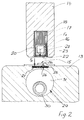
- FIG. 2 which enlarges area A in FIG. 1 shows the welding cooling jaw 14, which is like the mandrel 13 runs in the longitudinal direction of a tube - for reasons only the overlap area 15 is clear shown a tube - with one by means of electrical Current excitable high-frequency coil 16 at their the Mandrel 13 facing end, which are in the same Length and direction as the welding cooling jaw 14 extends.
- the coil 16 is in a core 17 made of ferrite (ferrite core 17) added, which is also of the same length and Direction as the welding cooling jaw 14 extends.
- the ferrite core 17 - even open at the bottom - is in one after open at the bottom (open at the bottom means towards the mandrel 13 open) slot 18 of the mandrel 13 added.
- Two opposite sides of the otherwise in cross section square coil 16 lie on inner walls 20, 21 of the slot of the ferrite core 17. Purpose of the ferrite core 17 is that through the coil 16 when current flows generated field (field lines of the same) into a certain Direction to steer towards the mandrel 13. in the bottom open end of the slot of the ferrite core 17 a corresponding to the longitudinal extent of the welding cooling jaw 14 Metal strip 22 is provided, between the metal strip 22, preferably made of copper, and one side of the coil 16 an insulation layer 23 is introduced.
- the coil 16 is hollow and is supported by a coolant, such as water flowed through.
- the mandrel 13 made of metal has an upward (means upward open towards the welding chilled beam 14) trough-shaped, preferably rectangular in cross-section 25 on, in the same direction and the same Length as the slot 18 of the mandrel 13 with ferrite core 17th and coil 16 extends and arranged symmetrically to slot 17 is.
- the recess 25 carries a on its bottom 26 Insulation layer 27 on which a lower metal band 28 is preferably made of copper.
- the mandrel 13 points a cooling 29 consisting of a coolant chamber 31, which is fed by a coolant tube 30, wherein the cooling medium, preferably water, from the coolant chamber is derived.
- the high-frequency field resulting from the supply of current to the coil 16 is divided into two individual fields F 1 (upper) F 2 (lower), field F 1 the upper metal strip 22 and field F 2 heats the lower metal strip 28.
- F 1 upper
- F 2 lower
- field F 1 the upper metal strip 22
- field F 2 heats the lower metal strip 28.
- the welding time i.e. the time to Melting and pressing adjustable by the duration the current flow through the coil 16 is adjustable.
- the pressing pressure of the welding cooling jaw 14 is corresponding required seam thickness variable, and that with the inventive Process achievable welding performance is adjustable by means of the current strength and duration of the current supply.
- the temperatures of the upper metal strip 22 and lower metal strip 28 can to adapt the inventive Process to certain seam shapes and plastics differently can be set. This can be about geometry (Width, thickness) of the tapes. For example, that with decreasing width of the upper metal band 22 the lower metal band is heated more with the same width.
- Tube tubes made of plastic-metal laminates stand out due to the current high level of development with almost invisible welds. Weld seams of comparable optical qualifications were despite all development efforts not yet accessible. With the method according to the invention, at Plastic or plastic laminate tubes now have seams of the same strength and optical qualifications like that of Plastic-metal laminate tubes can be produced.
Landscapes
- Engineering & Computer Science (AREA)
- Mechanical Engineering (AREA)
- Physics & Mathematics (AREA)
- Thermal Sciences (AREA)
- Lining Or Joining Of Plastics Or The Like (AREA)
- Extrusion Moulding Of Plastics Or The Like (AREA)
- Treatments Of Macromolecular Shaped Articles (AREA)
- Laminated Bodies (AREA)
Description
- Fig. 1:
- Eine Vorrichtung zur Durchführung des Verfahrens in Arbeitsstellung in Vorderansicht im Schnitt; und
- Fig. 2
- eine Einzelheit bei A, d.h. eine vergrösserte Darstellung einer Schweiss-Kühlbacke und eines Dornes in Vorderansicht im Schnitt mit Folie, die Schweiss-Kühlbacke in Auffahrtstellung.
Claims (4)
- Verfahren zur Herstellung eines rohrförmigen Hohlkörpers aus einer Kunststoff-Folie aus einem den Hohlkörper in seiner Abwicklung darstellenden Zuschnittes (Z), dessen überlappenden Ränder vermittels eines hochfrequenten Feldes aufgeschmolzen, in aufgeschmolzenem Zustand unter Anwendung von Druck verpresst und anschliessend gekühlt werden, dadurch gekennzeichnet, dass das hochfrequente Feld auf ein auf die Oberseite der Überlappung (15) einwirkendes Feld (F1) und ein auf die Unterseite der Überlappung (15) einwirkendes Feld (F2) aufgeteilt wird.
- Verfahren nach Anspruch 1, dadurch gekennzeichnet, dass die Felder (F1, F2) zur Aufschmelzung der Ober-und Unterseite der Ueberlappung (15) in ein sich erwärmendes oberes Metallband (22) und ein sich erwärmendes unteres Metallband (28) eingeleitet werden.
- Verfahren nach Anspruch 1 oder 2, dadurch gekennzeichnet, dass durch entsprechende Bemessung der Felder (F1,F2) die Metallbänder (22,28) unterschiedlich stark aufgeheizt werden.
- Verfahren nach Anspruch 3, dadurch gekennzeichnet, dass durch Verkleinerung der Breite des oberen Metallbandes (22) bei gleichbleibender Breite des unteren Metallbandes (28) mehr Energie in das untere Metallband eingetragen wird.
Applications Claiming Priority (3)
| Application Number | Priority Date | Filing Date | Title |
|---|---|---|---|
| CH1412/93 | 1993-05-07 | ||
| CH01412/93A CH688229A5 (de) | 1993-05-07 | 1993-05-07 | Verfahren zur Herstellung eines rohrfoermigen Hohlkoerpers. |
| CH141293 | 1993-05-07 |
Publications (3)
| Publication Number | Publication Date |
|---|---|
| EP0628399A2 EP0628399A2 (de) | 1994-12-14 |
| EP0628399A3 EP0628399A3 (de) | 1996-06-12 |
| EP0628399B1 true EP0628399B1 (de) | 2000-08-02 |
Family
ID=4209846
Family Applications (1)
| Application Number | Title | Priority Date | Filing Date |
|---|---|---|---|
| EP19940810269 Expired - Lifetime EP0628399B1 (de) | 1993-05-07 | 1994-05-06 | Verfahren zur Herstellung eines rohrförmigen Hohlkörpers |
Country Status (5)
| Country | Link |
|---|---|
| EP (1) | EP0628399B1 (de) |
| CN (1) | CN1103355A (de) |
| AT (1) | ATE195096T1 (de) |
| CH (1) | CH688229A5 (de) |
| DE (1) | DE59409465D1 (de) |
Cited By (3)
| Publication number | Priority date | Publication date | Assignee | Title |
|---|---|---|---|---|
| EP2319681A1 (de) | 2009-11-06 | 2011-05-11 | PackSys Global (Switzerland) Ltd. | Schweissverfahren mit einem antiadhäsiven flüssigen Medium, Beaufschlagungseinrichtung dieses Mediums sowie Schweissvorrichtung |
| EP4003703B1 (de) * | 2019-07-29 | 2024-12-04 | SIG Services AG | Impulsheisssiegeln eines heisssiegelbaren folienmaterials |
| EP4003706B1 (de) * | 2019-07-29 | 2024-12-04 | SIG Services AG | Kontinuierliche bewegungsimpuls-heisssiegelung von folienmaterial |
Families Citing this family (8)
| Publication number | Priority date | Publication date | Assignee | Title |
|---|---|---|---|---|
| CN101020359B (zh) * | 2007-02-14 | 2010-06-02 | 东莞中志鞋材有限公司 | 塑胶片材有缝熔接成管状的制造工艺及其设备 |
| US8906187B2 (en) | 2008-06-25 | 2014-12-09 | Colgate-Palmolive Company | Method of making shoulder/nozzles with film barrier liners |
| JP4626687B2 (ja) | 2008-08-19 | 2011-02-09 | トヨタ自動車株式会社 | 樹脂と金属との接合方法 |
| FR2987305B1 (fr) * | 2012-02-29 | 2017-02-10 | Daher Aerospace | Procede et dispositif pour le soudage a haute temperature d'un raidisseur sur un panneau composite a matrice thermoplastique |
| CN108501387B (zh) * | 2018-05-10 | 2024-08-06 | 淄博洁林塑料制管有限公司 | 一种塑料袋或塑料管热封装置 |
| NL2023583B1 (en) * | 2019-07-29 | 2021-02-22 | Bossar Holding B V | Production of collapsible pouches having a fitment |
| NL2023584B1 (en) * | 2019-07-29 | 2021-02-22 | Bossar Holding B V | Impulse heat sealing of a heat-sealable film material |
| US11904555B2 (en) * | 2022-01-03 | 2024-02-20 | Rohr, Inc. | Induction welding of thermoplastic with metallic strips |
Family Cites Families (5)
| Publication number | Priority date | Publication date | Assignee | Title |
|---|---|---|---|---|
| FR1566693A (de) * | 1968-03-27 | 1969-05-09 | ||
| GB1468262A (en) * | 1974-01-28 | 1977-03-23 | Griffin Ltd D | Methods of and apparatus for manufacturing electrically-powered heating panels |
| CH611223A5 (de) * | 1976-10-06 | 1979-05-31 | Karl Maegerle | |
| CH670797A5 (de) * | 1986-10-15 | 1989-07-14 | Maegerle Karl Lizenz | |
| EP0409021B1 (de) * | 1989-07-21 | 1997-02-19 | Kmk Lizence Ltd. | Vorrichtung und Verfahren zur Herstellung von Rohrkörpern |
-
1993
- 1993-05-07 CH CH01412/93A patent/CH688229A5/de not_active IP Right Cessation
-
1994
- 1994-05-06 EP EP19940810269 patent/EP0628399B1/de not_active Expired - Lifetime
- 1994-05-06 DE DE59409465T patent/DE59409465D1/de not_active Expired - Lifetime
- 1994-05-06 AT AT94810269T patent/ATE195096T1/de not_active IP Right Cessation
- 1994-05-07 CN CN94105850A patent/CN1103355A/zh active Pending
Cited By (4)
| Publication number | Priority date | Publication date | Assignee | Title |
|---|---|---|---|---|
| EP2319681A1 (de) | 2009-11-06 | 2011-05-11 | PackSys Global (Switzerland) Ltd. | Schweissverfahren mit einem antiadhäsiven flüssigen Medium, Beaufschlagungseinrichtung dieses Mediums sowie Schweissvorrichtung |
| DE102009053883A1 (de) | 2009-11-06 | 2011-05-12 | Packsys Global Ltd. | Schweißverfahren, Beaufschlagungseinrichtung sowie Schweißvorrichtung |
| EP4003703B1 (de) * | 2019-07-29 | 2024-12-04 | SIG Services AG | Impulsheisssiegeln eines heisssiegelbaren folienmaterials |
| EP4003706B1 (de) * | 2019-07-29 | 2024-12-04 | SIG Services AG | Kontinuierliche bewegungsimpuls-heisssiegelung von folienmaterial |
Also Published As
| Publication number | Publication date |
|---|---|
| EP0628399A2 (de) | 1994-12-14 |
| CN1103355A (zh) | 1995-06-07 |
| EP0628399A3 (de) | 1996-06-12 |
| DE59409465D1 (de) | 2000-09-07 |
| CH688229A5 (de) | 1997-06-30 |
| ATE195096T1 (de) | 2000-08-15 |
Similar Documents
| Publication | Publication Date | Title |
|---|---|---|
| DE69019998T2 (de) | Elektroschweissverbindung und deren Verwendung in einem Heisswasserverteiler. | |
| EP0628399B1 (de) | Verfahren zur Herstellung eines rohrförmigen Hohlkörpers | |
| DE19502140C1 (de) | Verfahren zum laserunterstützten Plattieren von Band und dessen Anwendung | |
| CH636541A5 (de) | Verfahren um einen streifen einer nichteisenmetallfolie mit einem waermeerweichbaren ueberzug zu einer rohrfoermigen form zu biegen und zu verschweissen. | |
| DE69602553T2 (de) | Stumpfschweissverfahren von zwei metallischen Blechplatten und nach diesem Verfahren hergestelltes Automobilteil | |
| EP0114398A2 (de) | Zusammendrückbarer Laminattubenbehälter | |
| DE3318815A1 (de) | Verfahren zur herstellung polygonaler verglasungen und induktionseinrichtung zum einsatz bei deren verbindung | |
| DE2649721C3 (de) | Behälter und Verfahren und Vorrichtung zu dessen Herstellung | |
| DE60312122T2 (de) | Schweissmaterialsanordnung mit einem flexiblen leitenden trägerblatt und verfahren zum schweissen von rohrförmigen elementen | |
| EP0299182B1 (de) | Verfahren zum Verschweissen von Rohrenden mit einem Rohrboden | |
| DE60314718T2 (de) | Verfahren zum widerstandsschweissen mit zwischenmaterial ohne träger sowie zwischenmaterial | |
| EP0264012B1 (de) | Verfahren zum Verbinden von sich überlappenden Rändern einer mehrschichtigen Folie und nach dem Verfahren hergestelltes Tubenrohr | |
| DE2461774A1 (de) | Verfahren zum schweissen von aluminium und aluminiumlegierungen in horizontaler schweisslage | |
| DE60219134T2 (de) | Schweißanlage mit inandergreifenden leitenden Endabschnitten | |
| DE4121427A1 (de) | Verfahren zur herstellung einer schweissnaht fuer tubenrohre | |
| WO2000010795A1 (de) | Verfahren zur herstellung von heissiegel-verpackungen und ein werkzeug zur durchführung des verfahrens | |
| CH500878A (de) | Verfahren und Vorrichtung zum Herstellen von Tuben mit geschweissten Nähten | |
| DE4017634A1 (de) | Verfahren und vorrichtung zur kontinuierlichen herstellung von geschweisstem metallrohr | |
| EP0459238A2 (de) | Verfahren zum Verschweissen wenigstens eines Bereichs einer Auflagefolie mit einer AufnahmeflÀ¤che einer Trägerschicht | |
| DE2656804C3 (de) | Verfahren zum T- oder Stumpfschweißen von Schichtkörpern mit einer Innenschicht aus thermoplastischem Schaumkunststoff | |
| DE3630625C2 (de) | ||
| CH609635A5 (en) | Packaging tube | |
| DE102009007582A1 (de) | Verfahren zum Verbinden sowie Verbindung eines Kapillarrohrs mit einem Stammrohr | |
| DE1936611A1 (de) | Heizband fuer Schweissanlagen | |
| DE1926838A1 (de) | Vorrichtung und Verfahren zur Herstellung von elektrischen Kabeln und damit hergestelltes elektrisches Kabel |
Legal Events
| Date | Code | Title | Description |
|---|---|---|---|
| PUAI | Public reference made under article 153(3) epc to a published international application that has entered the european phase |
Free format text: ORIGINAL CODE: 0009012 |
|
| AK | Designated contracting states |
Kind code of ref document: A2 Designated state(s): AT BE CH DE DK ES FR GB IT LI NL SE |
|
| 17P | Request for examination filed |
Effective date: 19950613 |
|
| RAP1 | Party data changed (applicant data changed or rights of an application transferred) |
Owner name: KMK LIZENCE LTD. |
|
| PUAL | Search report despatched |
Free format text: ORIGINAL CODE: 0009013 |
|
| AK | Designated contracting states |
Kind code of ref document: A3 Designated state(s): AT BE CH DE DK ES FR GB IT LI NL SE |
|
| 17Q | First examination report despatched |
Effective date: 19980519 |
|
| GRAG | Despatch of communication of intention to grant |
Free format text: ORIGINAL CODE: EPIDOS AGRA |
|
| GRAG | Despatch of communication of intention to grant |
Free format text: ORIGINAL CODE: EPIDOS AGRA |
|
| GRAH | Despatch of communication of intention to grant a patent |
Free format text: ORIGINAL CODE: EPIDOS IGRA |
|
| GRAH | Despatch of communication of intention to grant a patent |
Free format text: ORIGINAL CODE: EPIDOS IGRA |
|
| GRAA | (expected) grant |
Free format text: ORIGINAL CODE: 0009210 |
|
| AK | Designated contracting states |
Kind code of ref document: B1 Designated state(s): AT BE CH DE DK ES FR GB IT LI NL SE |
|
| PG25 | Lapsed in a contracting state [announced via postgrant information from national office to epo] |
Ref country code: NL Free format text: LAPSE BECAUSE OF FAILURE TO SUBMIT A TRANSLATION OF THE DESCRIPTION OR TO PAY THE FEE WITHIN THE PRESCRIBED TIME-LIMIT Effective date: 20000802 Ref country code: IT Free format text: LAPSE BECAUSE OF FAILURE TO SUBMIT A TRANSLATION OF THE DESCRIPTION OR TO PAY THE FEE WITHIN THE PRE;WARNING: LAPSES OF ITALIAN PATENTS WITH EFFECTIVE DATE BEFORE 2007 MAY HAVE OCCURRED AT ANY TIME BEFORE 2007. THE CORRECT EFFECTIVE DATE MAY BE DIFFERENT FROM THE ONE RECORDED.SCRIBED TIME-LIMIT Effective date: 20000802 Ref country code: GB Free format text: LAPSE BECAUSE OF FAILURE TO SUBMIT A TRANSLATION OF THE DESCRIPTION OR TO PAY THE FEE WITHIN THE PRESCRIBED TIME-LIMIT Effective date: 20000802 Ref country code: FR Free format text: LAPSE BECAUSE OF FAILURE TO SUBMIT A TRANSLATION OF THE DESCRIPTION OR TO PAY THE FEE WITHIN THE PRESCRIBED TIME-LIMIT Effective date: 20000802 Ref country code: ES Free format text: THE PATENT HAS BEEN ANNULLED BY A DECISION OF A NATIONAL AUTHORITY Effective date: 20000802 |
|
| REF | Corresponds to: |
Ref document number: 195096 Country of ref document: AT Date of ref document: 20000815 Kind code of ref document: T |
|
| REG | Reference to a national code |
Ref country code: CH Ref legal event code: EP |
|
| REF | Corresponds to: |
Ref document number: 59409465 Country of ref document: DE Date of ref document: 20000907 |
|
| PG25 | Lapsed in a contracting state [announced via postgrant information from national office to epo] |
Ref country code: SE Free format text: LAPSE BECAUSE OF FAILURE TO SUBMIT A TRANSLATION OF THE DESCRIPTION OR TO PAY THE FEE WITHIN THE PRESCRIBED TIME-LIMIT Effective date: 20001102 Ref country code: DK Free format text: LAPSE BECAUSE OF FAILURE TO SUBMIT A TRANSLATION OF THE DESCRIPTION OR TO PAY THE FEE WITHIN THE PRESCRIBED TIME-LIMIT Effective date: 20001102 |
|
| REG | Reference to a national code |
Ref country code: CH Ref legal event code: NV Representative=s name: HIEBSCH & PEEGE AG PATENTANWAELTE |
|
| NLV1 | Nl: lapsed or annulled due to failure to fulfill the requirements of art. 29p and 29m of the patents act | ||
| GBV | Gb: ep patent (uk) treated as always having been void in accordance with gb section 77(7)/1977 [no translation filed] |
Effective date: 20000802 |
|
| PG25 | Lapsed in a contracting state [announced via postgrant information from national office to epo] |
Ref country code: AT Free format text: LAPSE BECAUSE OF NON-PAYMENT OF DUE FEES Effective date: 20010506 |
|
| PG25 | Lapsed in a contracting state [announced via postgrant information from national office to epo] |
Ref country code: BE Free format text: LAPSE BECAUSE OF NON-PAYMENT OF DUE FEES Effective date: 20010531 |
|
| PLBE | No opposition filed within time limit |
Free format text: ORIGINAL CODE: 0009261 |
|
| STAA | Information on the status of an ep patent application or granted ep patent |
Free format text: STATUS: NO OPPOSITION FILED WITHIN TIME LIMIT |
|
| 26N | No opposition filed | ||
| BERE | Be: lapsed |
Owner name: KMK LIZENCE LTD Effective date: 20010531 |
|
| REG | Reference to a national code |
Ref country code: CH Ref legal event code: PFA Owner name: KMK LIZENCE LTD. Free format text: KMK LIZENCE LTD.#SIXTH FLOOR, CERNE HOUSE#CHAUSSEE, PORT LOUIS (MU) -TRANSFER TO- KMK LIZENCE LTD.#SIXTH FLOOR, CERNE HOUSE#CHAUSSEE, PORT LOUIS (MU) |
|
| PGFP | Annual fee paid to national office [announced via postgrant information from national office to epo] |
Ref country code: DE Payment date: 20120523 Year of fee payment: 19 |
|
| PGFP | Annual fee paid to national office [announced via postgrant information from national office to epo] |
Ref country code: CH Payment date: 20130523 Year of fee payment: 20 |
|
| PG25 | Lapsed in a contracting state [announced via postgrant information from national office to epo] |
Ref country code: DE Free format text: LAPSE BECAUSE OF NON-PAYMENT OF DUE FEES Effective date: 20131203 |
|
| REG | Reference to a national code |
Ref country code: DE Ref legal event code: R119 Ref document number: 59409465 Country of ref document: DE Effective date: 20131203 |
|
| REG | Reference to a national code |
Ref country code: CH Ref legal event code: PL |