EP0627623B1 - Verfahren und Vorrichtung zur Bestimmung der Struktur von Garnen im Bereich ihrer Oberfläche - Google Patents
Verfahren und Vorrichtung zur Bestimmung der Struktur von Garnen im Bereich ihrer Oberfläche Download PDFInfo
- Publication number
- EP0627623B1 EP0627623B1 EP19940104253 EP94104253A EP0627623B1 EP 0627623 B1 EP0627623 B1 EP 0627623B1 EP 19940104253 EP19940104253 EP 19940104253 EP 94104253 A EP94104253 A EP 94104253A EP 0627623 B1 EP0627623 B1 EP 0627623B1
- Authority
- EP
- European Patent Office
- Prior art keywords
- yarn
- sensor
- elements
- light
- determined
- Prior art date
- Legal status (The legal status is an assumption and is not a legal conclusion. Google has not performed a legal analysis and makes no representation as to the accuracy of the status listed.)
- Expired - Lifetime
Links
- 238000000034 method Methods 0.000 title claims description 17
- 239000000835 fiber Substances 0.000 claims description 17
- 238000005259 measurement Methods 0.000 claims description 13
- 238000011156 evaluation Methods 0.000 claims description 8
- 239000012535 impurity Substances 0.000 claims description 4
- 238000003384 imaging method Methods 0.000 claims description 3
- 239000011159 matrix material Substances 0.000 claims description 2
- 238000012545 processing Methods 0.000 claims description 2
- 238000005516 engineering process Methods 0.000 description 3
- 239000004753 textile Substances 0.000 description 3
- 238000003491 array Methods 0.000 description 2
- 238000012512 characterization method Methods 0.000 description 2
- 230000001427 coherent effect Effects 0.000 description 2
- 238000001514 detection method Methods 0.000 description 2
- 230000033001 locomotion Effects 0.000 description 2
- 230000003287 optical effect Effects 0.000 description 2
- 230000011664 signaling Effects 0.000 description 2
- 230000002159 abnormal effect Effects 0.000 description 1
- 230000002745 absorbent Effects 0.000 description 1
- 239000002250 absorbent Substances 0.000 description 1
- 230000003044 adaptive effect Effects 0.000 description 1
- 238000013528 artificial neural network Methods 0.000 description 1
- 230000015572 biosynthetic process Effects 0.000 description 1
- 230000006378 damage Effects 0.000 description 1
- 230000001419 dependent effect Effects 0.000 description 1
- 230000001066 destructive effect Effects 0.000 description 1
- 239000004744 fabric Substances 0.000 description 1
- 238000001914 filtration Methods 0.000 description 1
- 238000005286 illumination Methods 0.000 description 1
- 238000013507 mapping Methods 0.000 description 1
- 238000010297 mechanical methods and process Methods 0.000 description 1
- 230000035945 sensitivity Effects 0.000 description 1
- 239000007787 solid Substances 0.000 description 1
- 238000012360 testing method Methods 0.000 description 1
- 230000036962 time dependent Effects 0.000 description 1
Images
Classifications
-
- G—PHYSICS
- G01—MEASURING; TESTING
- G01N—INVESTIGATING OR ANALYSING MATERIALS BY DETERMINING THEIR CHEMICAL OR PHYSICAL PROPERTIES
- G01N33/00—Investigating or analysing materials by specific methods not covered by groups G01N1/00 - G01N31/00
- G01N33/36—Textiles
- G01N33/365—Filiform textiles, e.g. yarns
Definitions
- optical methods for online determination of rotation fluctuations known on machines. This type of procedure are, for example, in CH-A-675 133, in US-A-4,887,155 and in DE-A-24 43 692.
- Diameter and twist angle of a yarn are not one Figure can be determined.
- a first is needed here small spot of light to determine the direction of the fibers and a second larger spot of light around the diameter of the yarn to determine.
- this solution there is also a coherent solid color Light provided, so that normal white or colored Light cannot be used.
- normal white or colored Light cannot be used.
- protruding Fibers and patterns in the light spot the measurement.
- the present invention relates to a method and an apparatus to determine the structure of yarns in the area their surface. That is in particular the structure of both including the actual yarn surface and the yarn edge of inclusions contained therein or of of this protruding fibers.
- This procedure is supposed to Work non-destructively and quickly and therefore also for online Measurement on running machines can be used and it should enable the determination of parameters for a Characteristic characterization of the yarn surfaces in terms of textile technology can be used.
- the object is achieved in that the light is guided to several sensor elements of the sensor, the Sensor elements have different structures and the Structuring images of typical types of the to be determined and structure contained in the light represent that electrical Processed signals from these sensor elements and from them the structure sought is determined.
- Different structuring of the sensor elements means in this context that the individual elements for example are differently oriented or masked. So they can Sensor elements for measuring rotation as a stripe pattern with various Angle of inclination or as differently inclined slot-shaped photodiodes, and for determining other structural features like, for example, of lower thirds, as different ones Copies of typical lower thirds should be trained.
- the device according to the invention is characterized in that that the sensor is made up of a plurality of photoelectric elements is structured with different structuring, the typical Features of illustrations contain and that an evaluation device for processing the delivered by the sensor elements Signals are provided which have a correlation matrix contains.
- a preferred embodiment of the device according to the invention is characterized in that the sensor elements by photoelectric arranged on an integrated photochip Elements are formed and that the photo chip in addition contains an integrated circuit for the evaluation.
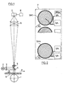
- a piece of a yarn G is shown below, which by means of transport, not shown, in the direction of Arrow P through a device for determining the surface structure of yarn G is promoted. Whether the funding is continuous and thus the measurement on the moving yarn, or whether the promotion gradually and the measurement on the still Yarn G is of secondary importance for the measurement as such Importance. In both cases, the yarn G is over a thread guide 1 performed, which for positioning the yarn in Beam path of the device and to stabilize it Location serves.
- the individual turns of the yarn G point relative to the yarn axis an incline a.
- yarn G is illuminated vertically reflections on its axis are used for determination the surface structure of the yarn to a suitable one Sensor are mapped.
- a surface structure primarily the twist of the yarn is meant are among them also more complicated structures, such as Cross fibers or lower thirds to understand both have very typical structures.
- the yarn G is through a light source 2 through a condenser 3 and a beam splitter mirror 4 illuminated vertically from above, and the light reflected from the yarn surface passes through the beam splitter mirror 4 and a lens 5 to a condenser 6, which collects the light and on one Photoelectric sensor 7 concentrated. This creates on the sensor 7 an image of the surface structure of the yarn G in an evaluation unit 8 connected to the sensor 7 is determined in more detail. Of course, yarn G can too be illuminated directly.
- the sensor 7 has several photo element arrangements on its surface with different structuring, with the structuring images of typical types of the defining structure.
- the image of the yarn surface becomes simultaneous or sequential with these individual structure types compared and it is in some sort of correlation process determined which of the structure types with the one to be determined Structure best matches.
- structure in the area of the surface is not only the structure of the actual yarn surface is meant, but also that of the yarn edge including fibers, which stand out from this, in which case the stand out Fibers within a certain distance from the thread edge will take into account, and including any Inclusions.
- impurities to the inclusions count especially those caused by foreign fibers are caused. Impurities of this type can be identified their shape and / or based on their color.
- the Sensor 7 is preferably designed as shown in FIG. 2, by placing several on an integrated photo chip are up to 20 and more in practice, stripe patterns SM1 to SMn are arranged by photo elements, which are characterized by the Distinguish angle b from the horizontal.
- the angle b for the stripe pattern SM1 is 40 ° and with stripe pattern SMn 50 °; the width of each strip is in the order of the diameter of the depicted Fibers.
- the individual strip-shaped photo elements emerging photo streams are alternately on one of two Switching points SP + and SP- guided and summed there, that is the even-numbered photo elements on one node and the odd numbers on the other SP + or SP-.
- the Evaluation unit 8 preferably by one on the photo chip integrated IC is formed, the difference of the total currents of the two circuit points determined and evaluated.
- the exact value of the fiber angle a is determined by interpolation from the differences in the total currents of the individual stripe patterns receive.
- the described method that of high-pass filtering (gradient formation) in the local area is independent of movement and works equally when standing and moving Yarn G. If per angle instead of a stripe pattern uses only a single slit-shaped photo element, then the measurement is motion-dependent, by moving A time-dependent signal is produced for each photo element.
- the signal portion coming from the fibers is passed through a high pass filter in the time domain, preferably one with a adaptive cutoff frequency, filtered out, for which the approximate Yarn speed must be known. And these high pass filtered ones Signal amplitudes of the individual photo elements then linearly interpolated.
- Fiber angle a and the diameter of the yarn G. determines the yarn twist.
- the measurement of the diameter is preferably done with one also on the photo chip contained row cell (photo element row, CCD row, Photodiode line or transistor line). Instead of a simple one Line patterns can be added by an additional absorbent Raster print photo element structures with any sensitivity be generated. Because it is possible any To calculate the spatial filter theoretically and then in the spatial space realize. For example, a rectangular filter in the Frequency space through Fourier transform a sin (x) / x filter in the local area. The determination of the yarn diameter enables it to regulate the sensor or the optics so that they always are centered on the thread.
- the yarn edge is different from the best in reflected light too seeing yarn surface can be seen particularly well in transmitted light it is recommended to use at least two different ones Types of lighting or lighting devices. These can be the measurements from one and the same place in the Perform chopping or at different points, in the latter case a synchronization of the two measurement types must be done.
- holograms of the surface structures could be neural Networks are made using different structural parameters could be examined and evaluated. These different Parameters span a multi-dimensional feature space, in which a certain structure forms a limited subspace.
- Diffractive optical elements and lens arrays for imaging one and the same piece of yarn on a large number of detectors are easy to implement with a laser as the source of illumination, which is known to be monochromatic and coherent Light works. Because when using monochromatic Light and a lens result that the Fourier transform of the location image in the focal plane of the lens in question lies. Because of this property you can get optimal filters define for structuring also in the Fourier plane and as Realize photo element structure. This has the advantage that Yarn position and depth of field do not play a major role, because the transform is position independent.
Landscapes
- Engineering & Computer Science (AREA)
- Textile Engineering (AREA)
- Health & Medical Sciences (AREA)
- Life Sciences & Earth Sciences (AREA)
- Chemical & Material Sciences (AREA)
- Food Science & Technology (AREA)
- Medicinal Chemistry (AREA)
- Physics & Mathematics (AREA)
- Analytical Chemistry (AREA)
- Biochemistry (AREA)
- General Health & Medical Sciences (AREA)
- General Physics & Mathematics (AREA)
- Immunology (AREA)
- Pathology (AREA)
- Treatment Of Fiber Materials (AREA)
- Investigating Materials By The Use Of Optical Means Adapted For Particular Applications (AREA)
Description
- Fig. 1
- eine schematische Darstellung einer erfindungsgemässen Vorrichtung; und
- Fig. 2
- einen stark vergrösserten Ausschnitt aus der Oberfläche des Sensors der Vorrichtung von Fig. 1.
Claims (11)
- Verfahren zur Bestimmung der Struktur von Garnen (G) im Bereiche ihrer Oberfläche, wobei das Garn beleuchtet und Licht vom Garn auf einen Sensor (7) geworfen wird, dadurch gekennzeichnet, dass das Licht auf mehrere Sensorelemente (SM1, SMn) des Sensors geführt wird, wobei die Sensorelemente unterschiedliche Strukturierung aufweisen und die Strukturierungen Abbilder von typischen Arten der zu bestimmenden und im Licht enthaltenen Struktur darstellen, dass elektrische Signale aus diesen Sensorelementen verarbeitet und daraus die gesuchte Struktur bestimmt wird.
- Verfahren nach Anspruch 1, dadurch gekennzeichnet, dass die Strukturierungen der Sensorelemente Merkmale der Struktur eines Abbildes der Oberfläche des Garns aufweisen.
- Verfahren nach Anspruch 1, dadurch gekennzeichnet, dass die Strukturierungen der Sensorelemente Merkmale der Fouriertransformation der Struktur der Oberfläche des Garns aufweisen.
- Verfahren nach Anspruch 1 oder 2 zur Bestimmung der Garndrehung, dadurch gekennzeichnet, dass mit den genannten Sensorelementen (SM1, SMn) der Faserwinkel (a) an der Oberfläche und mit einem weiteren Detektor der Durchmesser des Garns (G) bestimmt und daraus die Garndrehung berechnet wird.
- Verfahren nach Anspruch 1 oder 2, dadurch gekennzeichnet, dass zur Bestimmung komplizierter Strukturen auf dem Sensor (7) fotoelektrische Abbildungen von für diese Strukturen typischen Merkmalen hergestellt und die Abbildung des Garns (G) über diese Detektoranordnung geführt wird.
- Verfahren nach Anspruch 5, dadurch gekennzeichnet, dass die zu bestimmenden Strukturen Garnverunreinigungen, insbesondere Verunreinigungen durch Fremdfasern sind.
- Vorrichtung zur Durchführung des Verfahrens nach Anspruch 1, mit einer Lichtquelle (2) zur Beleuchtung eines Garns (G) und einem Sensor (7) zum Empfangen des Lichts vom Garn, dadurch gekennzeichnet, dass der Sensor (7) aus einer Mehrzahl von fotoelektrischen Elementen (SM1, SMn) mit unterschiedlicher Strukturierung aufgebaut ist, die typische Merkmale von Abbildungen enthalten, und dass eine Auswerteeinrichtung (8) zur Verarbeitung der von den Sensorelementen gelieferten Signale vorgesehen ist, welche eine Korrelationsmatrix enthält.
- Vorrichtung nach Anspruch 7, dadurch gekennzeichnet, dass die Sensorelemente (SM1, SMn) durch auf einem integrierten Fotochip (7) angeordnete Fotoelemente gebildet sind, und dass der Fotochip zusätzlich integrierte Schaltkreise für die Auswertung enthält.
- Vorrichtung nach Anspruch 8, dadurch gekennzeichnet, dass die fotoelektrischen Elemente (SM1, SMn) durch ein Streifenmuster von Fotoelementen gebildet und die Fotoströme der einzelnen Fotoelemente abwechselnd auf einen von zwei Schaltungspunkten (SP+, SP-) geführt sind, wo eine Summierung erfolgt, und dass die Differenzen der Summenströme der beiden Schaltungspunkte ein Mass für die Uebereinstimmung der Struktur des betreffenden Streifenmusters mit der untersuchten Struktur bildet.
- Vorrichtung nach Anspruch 8, dadurch gekennzeichnet, dass auf dem integrierten Fotochip (7) eine zweite Art von Sensorelementen zur Bestimmung eines weiteren Garnmerkmals angeordnet ist.
- Vorrichtung nach Anspruch 7, dadurch gekennzeichnet, dass die Anordnung zur Abbildung der Garnoberfläche ein sogenanntes Linsenarray zur Abbildung eines identischen Garn stücks auf mehrere Sensoren enthält.
Applications Claiming Priority (6)
| Application Number | Priority Date | Filing Date | Title |
|---|---|---|---|
| CH984/93 | 1993-03-31 | ||
| CH98493 | 1993-03-31 | ||
| CH98493 | 1993-03-31 | ||
| CH102293 | 1993-04-02 | ||
| CH1022/93A CH685071A5 (de) | 1993-04-02 | 1993-04-02 | Verfahren und Vorrichtung zur Bestimmung der Struktur von Garnen im Bereich ihrer Oberfläche. |
| CH1022/93 | 1993-04-02 |
Publications (3)
| Publication Number | Publication Date |
|---|---|
| EP0627623A2 EP0627623A2 (de) | 1994-12-07 |
| EP0627623A3 EP0627623A3 (de) | 1997-03-05 |
| EP0627623B1 true EP0627623B1 (de) | 2001-08-08 |
Family
ID=25686312
Family Applications (1)
| Application Number | Title | Priority Date | Filing Date |
|---|---|---|---|
| EP19940104253 Expired - Lifetime EP0627623B1 (de) | 1993-03-31 | 1994-03-18 | Verfahren und Vorrichtung zur Bestimmung der Struktur von Garnen im Bereich ihrer Oberfläche |
Country Status (2)
| Country | Link |
|---|---|
| EP (1) | EP0627623B1 (de) |
| DE (1) | DE59409818D1 (de) |
Families Citing this family (1)
| Publication number | Priority date | Publication date | Assignee | Title |
|---|---|---|---|---|
| CZ2022522A3 (cs) | 2022-12-12 | 2024-06-19 | Rieter Cz S.R.O. | Způsob řízení technologického procesu na dopřádacím stroji, dopřádací stroj k provádění způsobu, počítačový program k provádění způsobu na dopřádacím stroji a počítačem čitelné médium s počítačovým programem |
Family Cites Families (8)
| Publication number | Priority date | Publication date | Assignee | Title |
|---|---|---|---|---|
| DE1798319A1 (de) * | 1967-09-26 | 1971-11-04 | Ct Scient Et Tech De L Ind Tex | Vorrichtung zur Messung von Textilgarn-Dickenfehlern und deren Klassierung nach Garndicke und Fehlerlaenge |
| DE2127219A1 (de) * | 1971-06-02 | 1972-12-28 | Morat Gmbh Franz | Bildanalysegerät zum Messen von Flächengrößen bei Bildmustern, z.B. bei Faserquerschnitten |
| DE2443692C3 (de) | 1974-09-12 | 1978-06-15 | Erwin Sick Gmbh Optik-Elektronik, 7808 Waldkirch | Verfahren und Vorrichtung zur Messung des Steigungswinkels von mit einer Drehung versehenen Garnen |
| CH643060A5 (de) * | 1979-11-20 | 1984-05-15 | Zellweger Uster Ag | Verfahren zur bestimmung des durchmessers oder des querschnittes eines faden- oder drahtfoermigen koerpers, vorrichtung zur ausfuehrung des verfahrens, sowie anwendung des verfahrens. |
| IT1169761B (it) | 1982-08-12 | 1987-06-03 | Unisearch Ltd | Misurazione continua della torsione di un filato |
| DE3641816A1 (de) | 1986-12-06 | 1988-06-16 | Robert Prof Dr Ing Massen | Verfahren und anordnung zur messung und/oder ueberwachung von eigenschaften von garnen und seilen |
| CH675133A5 (de) | 1987-07-06 | 1990-08-31 | Zellweger Uster Ag | |
| FR2657959B1 (fr) | 1990-02-06 | 1992-04-30 | Superba Sa | Procede et dispositif pour mesurer la torsion d'un fil textile. |
-
1994
- 1994-03-18 DE DE59409818T patent/DE59409818D1/de not_active Expired - Fee Related
- 1994-03-18 EP EP19940104253 patent/EP0627623B1/de not_active Expired - Lifetime
Also Published As
| Publication number | Publication date |
|---|---|
| DE59409818D1 (de) | 2001-09-13 |
| EP0627623A2 (de) | 1994-12-07 |
| EP0627623A3 (de) | 1997-03-05 |
Similar Documents
| Publication | Publication Date | Title |
|---|---|---|
| EP0924493B1 (de) | Durchmessermessung mit Beugungssäumen sowie elektronische Verschmutzungskorrektur | |
| DE3110287C2 (de) | ||
| DE3204876C2 (de) | Vorrichtung zur Bestimmung des Refraktionszustandes des menschlichen Auges | |
| DE3410421C2 (de) | Verfahren und Vorrichtung zum Erfassen einer linienförmigen ersten Markierung und einer linienförmigen zweiten Markierung | |
| DE68908094T2 (de) | Teilchenmessvorrichtung. | |
| DE3603235A1 (de) | Vorrichtung und verfahren zum analysieren von parametern eines faserigen substrats | |
| DE2214191A1 (de) | Verfahren zum Bestimmen der Faserorientierung in Papier oder desgleichen mit Hilfe vom Papier reflektierten Lichts | |
| DE2354141C2 (de) | Optisches Meßverfahren zum Untersuchen von Oberflächen und Einrichtung zur Durchführung des Verfahrens | |
| DE2256736B2 (de) | Meßanordnung zur automatischen Prüfung der Oberflächenbeschaffenheit und Ebenheit einer Werkstückoberfläche | |
| CH643060A5 (de) | Verfahren zur bestimmung des durchmessers oder des querschnittes eines faden- oder drahtfoermigen koerpers, vorrichtung zur ausfuehrung des verfahrens, sowie anwendung des verfahrens. | |
| CH675133A5 (de) | ||
| DE69927367T2 (de) | Optoelektronische Formerfassung durch chromatische Kodierung mit Beleuchtungsebenen | |
| DE3926349A1 (de) | Optische fehlerinspektionsvorrichtung | |
| EP0715165A1 (de) | Verfahren und Vorrichtung zur Erfassung von Eigenschaften an langgestreckten Körpern | |
| AT516759B1 (de) | Vorrichtung und Verfahren zur Ermittlung der Anzahl an Feststoffpartikeln in einem Fluidstrom | |
| CH679428A5 (de) | ||
| CH685071A5 (de) | Verfahren und Vorrichtung zur Bestimmung der Struktur von Garnen im Bereich ihrer Oberfläche. | |
| DE69224066T2 (de) | Sonde zur Oberflächenmessung | |
| EP4117463B1 (de) | Messanordnung und verfahren zur optischen prüfung von artikeln der tabakverarbeitenden industrie | |
| CH628425A5 (de) | Verfahren und vorrichtung zur kontaktlosen messung linearer wegstrecken, insbesondere des durchmessers. | |
| DE69104423T2 (de) | Verfahren und vorrichtung zur messung der verwindung eines textilgarns. | |
| DE68917674T2 (de) | Optische Messanordnung zur Augenuntersuchung. | |
| DE60202435T2 (de) | Optische Methode und Vorrichtung zur Messung geometrischer Grössen | |
| CH440734A (de) | Einrichtung zum Bestimmen von Abmessungen an Körpern | |
| EP0627623A2 (de) | Verfahren und Vorrichtung zur Bestimmung der Struktur von Garnen im Bereich ihrer Oberfläche |
Legal Events
| Date | Code | Title | Description |
|---|---|---|---|
| PUAI | Public reference made under article 153(3) epc to a published international application that has entered the european phase |
Free format text: ORIGINAL CODE: 0009012 |
|
| AK | Designated contracting states |
Kind code of ref document: A2 Designated state(s): BE DE ES FR GB IT |
|
| PUAL | Search report despatched |
Free format text: ORIGINAL CODE: 0009013 |
|
| AK | Designated contracting states |
Kind code of ref document: A3 Designated state(s): BE DE ES FR GB IT |
|
| 17P | Request for examination filed |
Effective date: 19970905 |
|
| 17Q | First examination report despatched |
Effective date: 19981015 |
|
| GRAG | Despatch of communication of intention to grant |
Free format text: ORIGINAL CODE: EPIDOS AGRA |
|
| GRAG | Despatch of communication of intention to grant |
Free format text: ORIGINAL CODE: EPIDOS AGRA |
|
| GRAH | Despatch of communication of intention to grant a patent |
Free format text: ORIGINAL CODE: EPIDOS IGRA |
|
| GRAH | Despatch of communication of intention to grant a patent |
Free format text: ORIGINAL CODE: EPIDOS IGRA |
|
| GRAA | (expected) grant |
Free format text: ORIGINAL CODE: 0009210 |
|
| AK | Designated contracting states |
Kind code of ref document: B1 Designated state(s): BE DE ES FR GB IT |
|
| GBT | Gb: translation of ep patent filed (gb section 77(6)(a)/1977) |
Effective date: 20010808 |
|
| ITF | It: translation for a ep patent filed | ||
| REF | Corresponds to: |
Ref document number: 59409818 Country of ref document: DE Date of ref document: 20010913 |
|
| REG | Reference to a national code |
Ref country code: GB Ref legal event code: IF02 |
|
| ET | Fr: translation filed | ||
| PG25 | Lapsed in a contracting state [announced via postgrant information from national office to epo] |
Ref country code: ES Free format text: LAPSE BECAUSE OF FAILURE TO SUBMIT A TRANSLATION OF THE DESCRIPTION OR TO PAY THE FEE WITHIN THE PRESCRIBED TIME-LIMIT Effective date: 20020228 |
|
| PG25 | Lapsed in a contracting state [announced via postgrant information from national office to epo] |
Ref country code: GB Free format text: LAPSE BECAUSE OF NON-PAYMENT OF DUE FEES Effective date: 20020318 |
|
| PG25 | Lapsed in a contracting state [announced via postgrant information from national office to epo] |
Ref country code: BE Free format text: LAPSE BECAUSE OF NON-PAYMENT OF DUE FEES Effective date: 20020331 |
|
| PLBE | No opposition filed within time limit |
Free format text: ORIGINAL CODE: 0009261 |
|
| STAA | Information on the status of an ep patent application or granted ep patent |
Free format text: STATUS: NO OPPOSITION FILED WITHIN TIME LIMIT |
|
| 26N | No opposition filed | ||
| BERE | Be: lapsed |
Owner name: *ZELLWEGER LUWA A.G. Effective date: 20020331 |
|
| PG25 | Lapsed in a contracting state [announced via postgrant information from national office to epo] |
Ref country code: DE Free format text: LAPSE BECAUSE OF NON-PAYMENT OF DUE FEES Effective date: 20021001 |
|
| GBPC | Gb: european patent ceased through non-payment of renewal fee |
Effective date: 20020318 |
|
| PG25 | Lapsed in a contracting state [announced via postgrant information from national office to epo] |
Ref country code: FR Free format text: LAPSE BECAUSE OF NON-PAYMENT OF DUE FEES Effective date: 20021129 |
|
| REG | Reference to a national code |
Ref country code: FR Ref legal event code: ST |
|
| PG25 | Lapsed in a contracting state [announced via postgrant information from national office to epo] |
Ref country code: IT Free format text: LAPSE BECAUSE OF NON-PAYMENT OF DUE FEES;WARNING: LAPSES OF ITALIAN PATENTS WITH EFFECTIVE DATE BEFORE 2007 MAY HAVE OCCURRED AT ANY TIME BEFORE 2007. THE CORRECT EFFECTIVE DATE MAY BE DIFFERENT FROM THE ONE RECORDED. Effective date: 20050318 |