EP0627313A2 - Tête d'enregistrement par jet d'encre et appareil d'enregistrement l'utilisant - Google Patents
Tête d'enregistrement par jet d'encre et appareil d'enregistrement l'utilisant Download PDFInfo
- Publication number
- EP0627313A2 EP0627313A2 EP94303770A EP94303770A EP0627313A2 EP 0627313 A2 EP0627313 A2 EP 0627313A2 EP 94303770 A EP94303770 A EP 94303770A EP 94303770 A EP94303770 A EP 94303770A EP 0627313 A2 EP0627313 A2 EP 0627313A2
- Authority
- EP
- European Patent Office
- Prior art keywords
- ink
- drive signal
- recording
- electrothermal
- datum
- Prior art date
- Legal status (The legal status is an assumption and is not a legal conclusion. Google has not performed a legal analysis and makes no representation as to the accuracy of the status listed.)
- Granted
Links
- 238000010438 heat treatment Methods 0.000 claims abstract description 35
- 239000000463 material Substances 0.000 claims description 11
- 238000012546 transfer Methods 0.000 claims description 7
- 239000000976 ink Substances 0.000 description 71
- 238000003079 width control Methods 0.000 description 14
- 239000007788 liquid Substances 0.000 description 11
- 230000004044 response Effects 0.000 description 11
- 238000010586 diagram Methods 0.000 description 7
- 238000011084 recovery Methods 0.000 description 6
- 238000004519 manufacturing process Methods 0.000 description 4
- 238000000034 method Methods 0.000 description 4
- 230000015572 biosynthetic process Effects 0.000 description 3
- 238000009835 boiling Methods 0.000 description 3
- 230000008859 change Effects 0.000 description 3
- 238000001035 drying Methods 0.000 description 3
- 230000000694 effects Effects 0.000 description 3
- 230000007246 mechanism Effects 0.000 description 3
- 230000008569 process Effects 0.000 description 3
- 238000004891 communication Methods 0.000 description 2
- 230000008602 contraction Effects 0.000 description 2
- 238000011161 development Methods 0.000 description 2
- 238000001704 evaporation Methods 0.000 description 2
- 230000008020 evaporation Effects 0.000 description 2
- 239000000758 substrate Substances 0.000 description 2
- 238000004140 cleaning Methods 0.000 description 1
- 239000003086 colorant Substances 0.000 description 1
- 230000007423 decrease Effects 0.000 description 1
- 238000007599 discharging Methods 0.000 description 1
- 230000010365 information processing Effects 0.000 description 1
- 230000010354 integration Effects 0.000 description 1
- 230000007774 longterm Effects 0.000 description 1
- 239000000203 mixture Substances 0.000 description 1
- 238000012986 modification Methods 0.000 description 1
- 230000004048 modification Effects 0.000 description 1
- 230000006911 nucleation Effects 0.000 description 1
- 238000010899 nucleation Methods 0.000 description 1
- 238000003825 pressing Methods 0.000 description 1
- 239000004065 semiconductor Substances 0.000 description 1
Images


Classifications
-
- B—PERFORMING OPERATIONS; TRANSPORTING
- B41—PRINTING; LINING MACHINES; TYPEWRITERS; STAMPS
- B41J—TYPEWRITERS; SELECTIVE PRINTING MECHANISMS, i.e. MECHANISMS PRINTING OTHERWISE THAN FROM A FORME; CORRECTION OF TYPOGRAPHICAL ERRORS
- B41J2/00—Typewriters or selective printing mechanisms characterised by the printing or marking process for which they are designed
- B41J2/005—Typewriters or selective printing mechanisms characterised by the printing or marking process for which they are designed characterised by bringing liquid or particles selectively into contact with a printing material
- B41J2/01—Ink jet
- B41J2/015—Ink jet characterised by the jet generation process
- B41J2/04—Ink jet characterised by the jet generation process generating single droplets or particles on demand
- B41J2/045—Ink jet characterised by the jet generation process generating single droplets or particles on demand by pressure, e.g. electromechanical transducers
- B41J2/04501—Control methods or devices therefor, e.g. driver circuits, control circuits
- B41J2/04541—Specific driving circuit
-
- B—PERFORMING OPERATIONS; TRANSPORTING
- B41—PRINTING; LINING MACHINES; TYPEWRITERS; STAMPS
- B41J—TYPEWRITERS; SELECTIVE PRINTING MECHANISMS, i.e. MECHANISMS PRINTING OTHERWISE THAN FROM A FORME; CORRECTION OF TYPOGRAPHICAL ERRORS
- B41J2/00—Typewriters or selective printing mechanisms characterised by the printing or marking process for which they are designed
- B41J2/005—Typewriters or selective printing mechanisms characterised by the printing or marking process for which they are designed characterised by bringing liquid or particles selectively into contact with a printing material
- B41J2/01—Ink jet
- B41J2/015—Ink jet characterised by the jet generation process
- B41J2/04—Ink jet characterised by the jet generation process generating single droplets or particles on demand
- B41J2/045—Ink jet characterised by the jet generation process generating single droplets or particles on demand by pressure, e.g. electromechanical transducers
- B41J2/04501—Control methods or devices therefor, e.g. driver circuits, control circuits
- B41J2/04543—Block driving
-
- B—PERFORMING OPERATIONS; TRANSPORTING
- B41—PRINTING; LINING MACHINES; TYPEWRITERS; STAMPS
- B41J—TYPEWRITERS; SELECTIVE PRINTING MECHANISMS, i.e. MECHANISMS PRINTING OTHERWISE THAN FROM A FORME; CORRECTION OF TYPOGRAPHICAL ERRORS
- B41J2/00—Typewriters or selective printing mechanisms characterised by the printing or marking process for which they are designed
- B41J2/005—Typewriters or selective printing mechanisms characterised by the printing or marking process for which they are designed characterised by bringing liquid or particles selectively into contact with a printing material
- B41J2/01—Ink jet
- B41J2/015—Ink jet characterised by the jet generation process
- B41J2/04—Ink jet characterised by the jet generation process generating single droplets or particles on demand
- B41J2/045—Ink jet characterised by the jet generation process generating single droplets or particles on demand by pressure, e.g. electromechanical transducers
- B41J2/04501—Control methods or devices therefor, e.g. driver circuits, control circuits
- B41J2/04553—Control methods or devices therefor, e.g. driver circuits, control circuits detecting ambient temperature
-
- B—PERFORMING OPERATIONS; TRANSPORTING
- B41—PRINTING; LINING MACHINES; TYPEWRITERS; STAMPS
- B41J—TYPEWRITERS; SELECTIVE PRINTING MECHANISMS, i.e. MECHANISMS PRINTING OTHERWISE THAN FROM A FORME; CORRECTION OF TYPOGRAPHICAL ERRORS
- B41J2/00—Typewriters or selective printing mechanisms characterised by the printing or marking process for which they are designed
- B41J2/005—Typewriters or selective printing mechanisms characterised by the printing or marking process for which they are designed characterised by bringing liquid or particles selectively into contact with a printing material
- B41J2/01—Ink jet
- B41J2/015—Ink jet characterised by the jet generation process
- B41J2/04—Ink jet characterised by the jet generation process generating single droplets or particles on demand
- B41J2/045—Ink jet characterised by the jet generation process generating single droplets or particles on demand by pressure, e.g. electromechanical transducers
- B41J2/04501—Control methods or devices therefor, e.g. driver circuits, control circuits
- B41J2/04563—Control methods or devices therefor, e.g. driver circuits, control circuits detecting head temperature; Ink temperature
-
- B—PERFORMING OPERATIONS; TRANSPORTING
- B41—PRINTING; LINING MACHINES; TYPEWRITERS; STAMPS
- B41J—TYPEWRITERS; SELECTIVE PRINTING MECHANISMS, i.e. MECHANISMS PRINTING OTHERWISE THAN FROM A FORME; CORRECTION OF TYPOGRAPHICAL ERRORS
- B41J2/00—Typewriters or selective printing mechanisms characterised by the printing or marking process for which they are designed
- B41J2/005—Typewriters or selective printing mechanisms characterised by the printing or marking process for which they are designed characterised by bringing liquid or particles selectively into contact with a printing material
- B41J2/01—Ink jet
- B41J2/015—Ink jet characterised by the jet generation process
- B41J2/04—Ink jet characterised by the jet generation process generating single droplets or particles on demand
- B41J2/045—Ink jet characterised by the jet generation process generating single droplets or particles on demand by pressure, e.g. electromechanical transducers
- B41J2/04501—Control methods or devices therefor, e.g. driver circuits, control circuits
- B41J2/0458—Control methods or devices therefor, e.g. driver circuits, control circuits controlling heads based on heating elements forming bubbles
-
- B—PERFORMING OPERATIONS; TRANSPORTING
- B41—PRINTING; LINING MACHINES; TYPEWRITERS; STAMPS
- B41J—TYPEWRITERS; SELECTIVE PRINTING MECHANISMS, i.e. MECHANISMS PRINTING OTHERWISE THAN FROM A FORME; CORRECTION OF TYPOGRAPHICAL ERRORS
- B41J2/00—Typewriters or selective printing mechanisms characterised by the printing or marking process for which they are designed
- B41J2/005—Typewriters or selective printing mechanisms characterised by the printing or marking process for which they are designed characterised by bringing liquid or particles selectively into contact with a printing material
- B41J2/01—Ink jet
- B41J2/015—Ink jet characterised by the jet generation process
- B41J2/04—Ink jet characterised by the jet generation process generating single droplets or particles on demand
- B41J2/045—Ink jet characterised by the jet generation process generating single droplets or particles on demand by pressure, e.g. electromechanical transducers
- B41J2/04501—Control methods or devices therefor, e.g. driver circuits, control circuits
- B41J2/04581—Control methods or devices therefor, e.g. driver circuits, control circuits controlling heads based on piezoelectric elements
-
- B—PERFORMING OPERATIONS; TRANSPORTING
- B41—PRINTING; LINING MACHINES; TYPEWRITERS; STAMPS
- B41J—TYPEWRITERS; SELECTIVE PRINTING MECHANISMS, i.e. MECHANISMS PRINTING OTHERWISE THAN FROM A FORME; CORRECTION OF TYPOGRAPHICAL ERRORS
- B41J2/00—Typewriters or selective printing mechanisms characterised by the printing or marking process for which they are designed
- B41J2/005—Typewriters or selective printing mechanisms characterised by the printing or marking process for which they are designed characterised by bringing liquid or particles selectively into contact with a printing material
- B41J2/01—Ink jet
- B41J2/015—Ink jet characterised by the jet generation process
- B41J2/04—Ink jet characterised by the jet generation process generating single droplets or particles on demand
- B41J2/045—Ink jet characterised by the jet generation process generating single droplets or particles on demand by pressure, e.g. electromechanical transducers
- B41J2/04501—Control methods or devices therefor, e.g. driver circuits, control circuits
- B41J2/04591—Width of the driving signal being adjusted
-
- B—PERFORMING OPERATIONS; TRANSPORTING
- B41—PRINTING; LINING MACHINES; TYPEWRITERS; STAMPS
- B41J—TYPEWRITERS; SELECTIVE PRINTING MECHANISMS, i.e. MECHANISMS PRINTING OTHERWISE THAN FROM A FORME; CORRECTION OF TYPOGRAPHICAL ERRORS
- B41J2/00—Typewriters or selective printing mechanisms characterised by the printing or marking process for which they are designed
- B41J2/005—Typewriters or selective printing mechanisms characterised by the printing or marking process for which they are designed characterised by bringing liquid or particles selectively into contact with a printing material
- B41J2/01—Ink jet
- B41J2/015—Ink jet characterised by the jet generation process
- B41J2/04—Ink jet characterised by the jet generation process generating single droplets or particles on demand
- B41J2/045—Ink jet characterised by the jet generation process generating single droplets or particles on demand by pressure, e.g. electromechanical transducers
- B41J2/04501—Control methods or devices therefor, e.g. driver circuits, control circuits
- B41J2/04598—Pre-pulse
Definitions
- the present invention relates to an ink jet recording head for ejecting ink droplet through an ejection outlet or ejection outlets using thermal energy and an ink jet recording apparatus using the ink jet recording head.
- droplets of ink are formed through one of various processes, and the droplets are deposited on a recording material such as recording paper or the like to effect the recording.
- a recording material such as recording paper or the like.
- an ink jet recording process using thermal energy for the droplet formation is advantageous in that multi-nozzle structure at high density can be easily accomplished, and therefore, high resolution and high quality image can be provided at high speed.
- a recording head in which a plurality of droplet formation means for electing ink droplets through ejection outlets by thermal energy applied to the ink, that is, the droplet formation means having electrothermal transducer element for heating the ink by being supplied with current pulses, and integration circuit (driver IC) for driving the electrothermal transducers, are formed on a common substrate.
- FIG 8 there is shown an example of such an ink jet recording head and a driver.
- Figure 9 illustrates drive timing therefor.
- a reference numeral 2 designated by a reference numeral 2 are electrothermal transducers corresponding to ink ejection outlets 13 (not shown).
- the same number of record data (SI) as the number of the electrothermal transducer 2 are sequentially transferred in synchronism with data transfer clock (CLK) into shift registers 4 in the driver IC3 by an image data generating circuit 22, as shown in Figure 9.
- the record data thus transferred are read in a latch circuit in accordance with input of latch signals (LAT).
- LAT latch signals
- the driver IC3 is sequentially rendered active in response to flip-flop (F/F) 6.
- the electrothermal transducers 2 for which the record data signals for the driver IC3 are on, are selectively energized in the order shown in Figure 9, only during on-state of the pulse width setting signal (END), by which the ink is ejected through the associated ejection outlets 13.
- a bubble is created in the ink in response to energization of the electrothermal transducer element, and the pressure produced by the bubble creation is used to eject the ink from the recording head to effect the recording. Therefore, it is desired that the ink is maintained stably in an ejectable state. For this purpose, a particular consideration is paid, which is peculiar to this type of the apparatus.
- the ink exists in the nozzles of the recording head even when the recording operation is not carried out, and therefore, some measure is taken against property change such as viscosity increase due to drying or evaporation of the ink in the nozzle.
- property change such as viscosity increase due to drying or evaporation of the ink in the nozzle.
- the orifices of the recording head are covered with a cap when the recording operation is not carried out to prevent the drying or evaporation of the ink, using capping means.
- the viscosity increase of the ink is unavoidable if only such a dry preventing means is used.
- the use has been made, in addition to the capping means, with a recovery mechanism by which the air in the cap covering the recording head is sucked to suck the ink out from the nozzle, or a pump or the like is used to apply pressure into the nozzle to forcedly eject the ink having the changed property, or idle ejection operations are carried out toward a portion outside the recording sheet to discharge the high viscosity ink in the nozzle.
- the recovery mechanism is usually automatically driven upon actuation of the main switch and so on. During the recording operation, it is desirable that it is operated at as long as possible intervals from the standpoint of reducing the ink consumption. against the ink property change due to non-use of the nozzle during the recording operation, the recording operation is frequently stopped at short intervals to carry out the ejection recovery operation. This decreases the overall recording speed.
- Japanese Laid-Open Patent Application Nos. 187364/1983 and 105967/1984 disclose that the electrothermal transducers are supplied with electric energy not enough to eject the ink even when the ejection signals therefor are not applied, so that the ink temperature is maintained within a predetermined range to provide satisfactory ejection against increase of the viscosity of the ink under the low temperature conditions or the like (preliminary heating). If this system is used, the apparatus becomes bulky in the case of an ink jet recording head having a relatively large number of ejection outlets with the driving elements shown in Figure 8.
- an ink jet head comprising: a plurality of electrothermal transducers for producing thermal energy contributable to ink ejection, storing means for storing image data for the electrothermal transducers; switching means for switching energization periods for the electrothermal transducers in accordance with the image data stored in the storing means; wherein during recording operation using the electrothermal transducers, when an image datum stored in the storing means is a first datum instructing recording, the switching means supplies to the corresponding electrothermal transducer a first drive signal for preliminary ink heating and a second drive signal for ejecting the ink, and when the image datum is a second datum not instructing recording, the switching means supplies the first drive signal to the corresponding electrothermal transducer element and does not supply the second drive signal.
- Figure 1 is a block diagram of a circuit structure according to a first embodiment of the present invention.
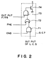
- Figure 2 is a block diagram showing details of a part of the circuit of Figure 1.
- Figure 3 illustrates drive timing of the circuit shown in Figure 1.
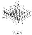
- Figure 4 illustrates an ink jet recording head applicable to the present invention.
- Figure 5 is a block diagram of a circuit structure according to a second embodiment of the present invention.
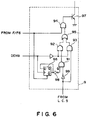
- Figure 6 is a block diagram showing details of a part of the circuit of Figure 5.
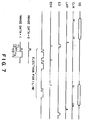
- Figure 7 illustrates drive timing of the circuit of Figure 5.
- Figure 8 is a perspective view of an ink jet recording head to which the present invention is applicable.
- Figure 9 is a block diagram of a circuit structure of a conventional ink jet recording apparatus.
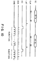
- Figure 10 illustrates drive timing of the circuit of Figure 9.
- FIG. 4 there is shown an ink jet recording head to which the present invention is applicable of a full-multi-type in which the ejection outlets are arranged over the entire width of a recording material.
- Designated by reference numeral 11 are heat generating register constituting electrothermal transducers 2 to eject the ink by creation of bubbles in the ink using film boiling. They are formed together with wiring on a substrate 12 through a manufacturing step which is similar to a semiconductor device manufacturing step.
- Designated by a reference 13A is a liquid passage forming member for forming ejection outlets 13 corresponding to the heat generating register 11 and liquid passages 14 respectively in communication therewith; 15 is a top plate.
- a common liquid chamber 16 is in communication with the liquid passages 14 and store the ink supplied from an unshown ink supply source.
- Figure 1 is a block diagram of an example of a circuit for the ink jet recording head having the above-described mechanical structure, according to an embodiment of the present invention.
- the same reference numerals as in Figure 8 are assigned to the elements having the corresponding functions.
- a driving elements on the recording head 1 comprises a shift register 4 for receiving image data SD, a latch circuit 5 for temporarily storing the image data in response to latch signals LAT after reception of the image data, a flip-flop circuit 6 to permit sequential energization of electrothermal transducer in response to energy supply instruction data ED and energy supply instruction data transfer clock ECK, and a gate circuit 7 for switching energization period for the electrothermal transducer in accordance with ejection drive pulse width control signal ENB for controlling energization period for ejection drive, supplied from election drive pulse width control circuit 26, preliminary heating pulse width control signal PHE for controlling energization period for preliminary heating drive, supplied from a preliminary heating pulse width control circuit 25, and an output of the latch circuit 5. They are integrated for adjacent plurality of bits.
- a head drive control circuit 20 in a main assembly of the recording apparatus comprises a heater drive source 21, a drive timing generating circuit 23, a preliminary heating pulse generating circuit 25, an ejection drive pulse generating circuit 26 and an image data generating circuit 22 and so on.
- the gate circuit 7, as shown in Figure 2, for example, comprises a combination of AND-gates 71, 72, or OR-gate 72, a driver circuit 74 or the like.
- FIG. 3 illustrates drive timing in this embodiment.
- the image data SD for one line of record constituted by the same number of bits as the number of electrothermal transducers 2 are supplied to the shift register 4 in synchronism with the image data transfer clock CLK, and they are stored in the latch circuit 5 in accordance with the latch signal LAT.
- energization instruction data ED are supplied in synchronism with the energization instruction data transfer clock ECK to enable the energization of the electrothermal transducers 2 in the driver element.
- the energy is supplied for the preliminary heating drive for all electrothermal transducers 2 in one block in response to the preliminary heating pulse width control signal PHE.
- the energization for the ejection drive is effected for only the bits for which the image data are in on-state.
- the preliminary heating drive and the ejection drive are carried out sequentially for each block for each production of the energization instruction data transfer block, in response to the image data SD and the energization instruction data ED.
- the operations are effected for all of the electrothermal transducers, so that ejection operations for one line are completed.
- the image data for the next line is stored in a first shift register, and after completion of the ejection operations for one line, the ejection operations for the next line are immediately initiated.
- the time period of the pulse width T1 of the preliminary heating pulse width control circuit PHE, the pulse width T3 of the ejection drive pulse width control signal ENB and the time period between the preliminary heating pulse and the ejection drive pulse may be different depending on the individual recording heads, and further depending on ambient temperature or the recording head temperature. Therefore, in this embodiment, they are controllable by the preliminary heating pulse width control circuit 25 and the ejection drive pulse width control circuit 26 on the basis of temperature data from a temperature sensor 8 mounted in the recording head or adjacent thereto.
- FIG. 5 is a circuit block diagram according to another embodiment of the present invention.
- the same reference numerals as in Figure 1 are applied to the elements having the corresponding functions.
- the preliminary heating pulse width control signal and the ejection drive pulse width control signal are commonly provided in the same signal double pulse drive control signal DENB, and the energization period of the electrothermal transducer element is switcheable depending on image data by energization period switching circuit 9 in the drive element.
- the double pulse drive control signal DENB produced by a pulse width control circuit 27 repeats on-state and off-state alternately for the preliminary heating pulse and the ejection drive pulse, and are supplied to the recording head.
- the energization period switching circuit 9 enables the energization of the electrothermal transducer element 2 when the double pulse drive control signal DENG is on, under the condition that the output of the latch circuit 5 having received the image data is on, that is, the image data is "1", when the output of the flip-flop F/F 6 is on.
- the electrothermal transducer 3 is energized when the preliminary heating pulse is produced or when the ejection drive pulse is inputted.
- the energization period switching circuit 9 enabled energization of the electrothermal transducer 2 only when the preliminary heating pulse is already supplied, but the energization is prohibited for the next ejection drive pulse input.
- Figure 6 illustrates detailed structures of the energization period switching circuit 9, which comprises AND-gates 91 - 94, OR-gate 95, flip-flop 96 and a driver circuit 97 and so on.
- the driver circuit 97 is driven through the AND-gate 91, 92 and OR-gate 95 and AND-gate 94, so that the electrothermal transducer 2 is energized for an on-period of the preliminary pulse.
- the flip-flop 96 is reversed and the reverse of the output Q ⁇ is "1".
- the double pulse drive control signal DENB is rendered on in response to the preliminary heating pulse in this state, the reverse output of the flip-flop 96 Q ⁇ becomes "0".
- the output is inverted by an inverter 98, and then is supplied to one output of the AND-gate 91.
- the output of the latch circuit 5 is supplied after being inverted by the inverter 99. Therefore, when the output of the latch circuit 9 is off, the output of the AND-gate 91 is "1". In this manner, the output of the AND-gate 92 is "1" during on-period of the preliminary heating pulse.
- the output is supplied to the AND-gate 94 through the OR-gate 95, and the driver circuit 97 is driven by the output, so that the electrothermal transducer 2 is energized during on-period of the preliminary heating pulse.
- Figure 7 illustrates drive timing in the embodiment of Figure 5.
- the image data for one line are supplied to the shift register 4, and the image data are stored in the latch circuit 5 in response to the latch signal LAT.
- energization instruction data ED are produced to enable energization of the electrothermal transducer elements 2 in the driving elements grouped into blocks.
- the double pulse drive control signal DENB only the preliminary heating drive is carried out for each of the bits having image data "0", and both of the preliminary heating drive and the ejection drive are carried out for the bits having the image data "1".
- the operations are carried out sequentially for all of the blocks of the electrothermal transducers 2, by which the ejection operation for one line is completed.
- the number of contacts for the signals and the numbers of signal lines between driving elements can be reduced, so that compact and low cost ink jet recording heads can be provided.
- a plurality of adjacent electrothermal transducers constitute one group, and they are integrated for each group.
- the driving element is provided for cach blocks of the electrothermal transducers which are sequentially driven. Therefore, the control signals are connected in series.
- the present invention is applicable to the case that the driving element is divided into a plurality of blocks with the sequentially driven block unit are constituted at an interval of a plurality of bits or the case that the control signals supplied to the recording head are grouped into a plurality of blocks separately actuated.
- Figure 10 shows an example of a multi-color ink jet recording apparatus in which a plurality of full-multi-type recording heads 1A, 1B, 1C and 1D using the above-described driving method, are disposed in parallel.
- the recording heads 1A, 1B, 1C and 1D eject cyan, magenta, yellow and black inks at predetermined timing through ejection outlet 13 onto the recording material 17.
- the image is recorded or printed on the recording material 17.
- the recording material 17 is a fan-fold sheet.
- Designated by reference numeral 18 is a sheet feeding roller; 19 is a discharging roller for cooperation with the feeding roller 18 to hold the recording material 17 at the recording position and for feeding it toward the discharge side in interrelation with the sheet feeding roller 18.
- the present invention is usable with any ink jet apparatus, such as those using electromechanical converter such as piezoelectric element, but is particularly suitably usable in an ink jet recording head and recording apparatus wherein thermal energy by an electrothermal transducer, laser beam or the like is used to cause a change of state of the ink to eject or discharge the ink. This is because the high density of the picture elements and the high resolution of the recording are possible.
- the typical structure and the operational principle are preferably the ones disclosed in U.S. Patent Nos. 4,723,129 and 4,740,796.
- the principle and structure are applicable to a so-called on-demand type recording system and a continuous type recording system.
- it is suitable for the on-demand type because the principle is such that at least one driving signal is applied to an electrothermal transducer disposed on a liquid (ink) retaining sheet or liquid passage, the driving signal being enough to provide such a quick temperature rise beyond a departure from nucleation boiling point, by which the thermal energy is provided by the electrothermal transducer to produce film boiling on the heating portion of the recording head, whereby a bubble can be formed in the liquid (ink) corresponding to each of the driving signals.
- the liquid (ink) is ejected through an ejection outlet to produce at least one droplet.
- the driving signal is preferably in the form of a pulse, because the development and contraction of the bubble can be effected instantaneously, and therefore, the liquid (ink) is ejected with quick response.
- the driving signal in the form of the pulse is preferably such as disclosed in U.S. Patents Nos. 4,463,359 and 4,345,262.
- the temperature increasing rate of the heating surface is preferably such as disclosed in U.S. Patent No. 4,313,124.
- the structure of the recording head may be as shown in U.S. Patent Nos. 4,558,333 and 4,459,600 wherein the heating portion is disposed at a bent portion, as well as the structure of the combination of the ejection outlet, liquid passage and the electrothermal transducer as disclosed in the above-mentioned patents.
- the present invention is applicable to the structure disclosed in Japanese Laid-Open Patent Application No. 123670/1984 wherein a common slit is used as the ejection outlet for plural electrothermal transducers, and to the structure disclosed in Japanese Laid-Open Patent Application No. 138461/1984 wherein an opening for absorbing pressure wave of the thermal energy is formed corresponding to the ejecting portion. This is because the present invention is effective to perform the recording operation with certainty and at high efficiency irrespective of the type of the recording head.
- the present invention is effectively applicable to a so-called full-line type recording head having a length corresponding to the maximum recording width.
- a recording head may comprise a single recording head and plural recording head combined to cover the maximum width.
- the present invention is applicable to a serial type recording head wherein the recording head is fixed on the main assembly, to a replaceable chip type recording head which is connected electrically with the main apparatus and can be supplied with the ink when it is mounted in the main assembly, or to a cartridge type recording head having an integral ink container.
- the provisions of the recovery means and/or the auxiliary means for the preliminary operation are preferable, because they can further stabilize the effects of the present invention.
- preliminary heating means which may be the electrothermal transducer, an additional heating element or a combination thereof.
- means for effecting preliminary ejection (not for the recording operation) can stabilize the recording operation.
- the recording head mountable may be a single corresponding to a single color ink, or may be plural corresponding to the plurality of ink materials having different recording color or density.
- the present invention is effectively applicable to an apparatus having at least one of a monochromatic mode mainly with black, a multi-color mode with different color ink materials and/or a full-color mode using the mixture of the colors, which may be an integrally formed recording unit or a combination of plural recording heads.
- the ink jet recording apparatus may be used as an output terminal of an information processing apparatus such as computer or the like, as a copying apparatus combined with an image reader or the like, or as a facsimile machine having information sending and receiving functions.
- the effective preliminary heating drive of the electrothermal transducer is possible during recording operation with simple structure and with small number of signal lines.
- the temperature of the recording head is made uniform, and the stabilized ink ejection is possible with simple structure, and high quality recording is possible.
- the intervals between ejection operations can be made longer, thus increasing the recording speed.
Landscapes
- Particle Formation And Scattering Control In Inkjet Printers (AREA)
- Ink Jet (AREA)
- Facsimile Heads (AREA)
Applications Claiming Priority (3)
| Application Number | Priority Date | Filing Date | Title |
|---|---|---|---|
| JP5124193A JPH06328722A (ja) | 1993-05-26 | 1993-05-26 | インクジェット記録ヘッド及び該インクジェット記録ヘッドを用いたインクジェット記録装置 |
| JP12419393 | 1993-05-26 | ||
| JP124193/93 | 1993-05-26 |
Publications (3)
| Publication Number | Publication Date |
|---|---|
| EP0627313A2 true EP0627313A2 (fr) | 1994-12-07 |
| EP0627313A3 EP0627313A3 (fr) | 1995-05-03 |
| EP0627313B1 EP0627313B1 (fr) | 1999-08-11 |
Family
ID=14879293
Family Applications (1)
| Application Number | Title | Priority Date | Filing Date |
|---|---|---|---|
| EP94303770A Expired - Lifetime EP0627313B1 (fr) | 1993-05-26 | 1994-05-25 | Tête d'enregistrement par jet d'encre et appareil d'enregistrement l'utilisant |
Country Status (5)
| Country | Link |
|---|---|
| US (1) | US6145948A (fr) |
| EP (1) | EP0627313B1 (fr) |
| JP (1) | JPH06328722A (fr) |
| AT (1) | ATE183139T1 (fr) |
| DE (1) | DE69419969T2 (fr) |
Cited By (4)
| Publication number | Priority date | Publication date | Assignee | Title |
|---|---|---|---|---|
| WO1997035167A2 (fr) * | 1996-03-15 | 1997-09-25 | Xaar Technology Limited | Fonctionnement d'un appareil de depot de gouttelettes |
| EP0811496A2 (fr) * | 1996-06-03 | 1997-12-10 | Nec Corporation | Commande des électrodes d'éjection d'encre dans un système à jet d'encre |
| EP0900657A3 (fr) * | 1997-09-08 | 1999-06-09 | Konica Corporation | Imprimante à jet d'encre |
| US6672711B2 (en) | 2000-08-04 | 2004-01-06 | Benq Corporation | Driving circuit capable of maintaining heat equilibrium of a print head nozzle |
Families Citing this family (13)
| Publication number | Priority date | Publication date | Assignee | Title |
|---|---|---|---|---|
| JP3339695B2 (ja) * | 1991-06-27 | 2002-10-28 | マツダ株式会社 | サンルーフ装置の制御機構 |
| US6116714A (en) | 1994-03-04 | 2000-09-12 | Canon Kabushiki Kaisha | Printing head, printing method and apparatus using same, and apparatus and method for correcting said printing head |
| JPH0939273A (ja) * | 1995-07-28 | 1997-02-10 | Matsushita Electric Ind Co Ltd | 階調印字制御装置 |
| US6309040B1 (en) | 1999-09-03 | 2001-10-30 | Hewlett-Packard Company | Signaling method for a pen driver circuit interface |
| JP2001150657A (ja) * | 1999-11-29 | 2001-06-05 | Canon Inc | 記録装置および記録方法 |
| JP2004306564A (ja) * | 2003-04-10 | 2004-11-04 | Canon Inc | 記録ヘッド用基板、記録ヘッド、記録ヘッドの温度制御方法、及び記録装置 |
| US20050007403A1 (en) * | 2003-07-07 | 2005-01-13 | Cheng-Lung Lee | Printing apparatus and method for maintaining temperature of a printhead |
| JP4965906B2 (ja) * | 2006-06-22 | 2012-07-04 | キヤノン株式会社 | 画像形成装置およびデータ生成方法 |
| US7722163B2 (en) | 2006-10-10 | 2010-05-25 | Silverbrook Research Pty Ltd | Printhead IC with clock recovery circuit |
| US7819494B2 (en) * | 2006-10-10 | 2010-10-26 | Silverbrook Research Pty Ltd | Printhead IC with multi-stage print data loading and firing |
| DE102007030566A1 (de) * | 2007-03-28 | 2008-10-02 | Man Roland Druckmaschinen Ag | Zerstörungsfreie Prüfverfahren der Aushärtungs- oder Trocknungsgrades von Farben und Lacken |
| JP5451042B2 (ja) * | 2007-12-03 | 2014-03-26 | キヤノン株式会社 | 記録ヘッド及び記録装置 |
| EP2252465B1 (fr) * | 2008-03-12 | 2015-05-06 | Hewlett-Packard Development Company, L.P. | Transfert d'un signal de déclenchement dans un dispositif d'éjection de fluide |
Citations (5)
| Publication number | Priority date | Publication date | Assignee | Title |
|---|---|---|---|---|
| US4560993A (en) * | 1983-03-07 | 1985-12-24 | Hitachi, Ltd. | Thermal printing method and thermal printer |
| US4791435A (en) * | 1987-07-23 | 1988-12-13 | Hewlett-Packard Company | Thermal inkjet printhead temperature control |
| US4804976A (en) * | 1988-02-22 | 1989-02-14 | Eastman Kodak Company | System for energizing thermal printer heating elements |
| GB2218380A (en) * | 1984-12-21 | 1989-11-15 | Canon Kk | Heating liquid in liquid discharge recording apparatus prior to discharge |
| US5107276A (en) * | 1989-07-03 | 1992-04-21 | Xerox Corporation | Thermal ink jet printhead with constant operating temperature |
Family Cites Families (15)
| Publication number | Priority date | Publication date | Assignee | Title |
|---|---|---|---|---|
| CA1127227A (fr) * | 1977-10-03 | 1982-07-06 | Ichiro Endo | Procede d'enregistrement a jet liquide et appareil d'enregistrement |
| US4330787A (en) * | 1978-10-31 | 1982-05-18 | Canon Kabushiki Kaisha | Liquid jet recording device |
| US4345262A (en) * | 1979-02-19 | 1982-08-17 | Canon Kabushiki Kaisha | Ink jet recording method |
| US4463359A (en) * | 1979-04-02 | 1984-07-31 | Canon Kabushiki Kaisha | Droplet generating method and apparatus thereof |
| US4313124A (en) * | 1979-05-18 | 1982-01-26 | Canon Kabushiki Kaisha | Liquid jet recording process and liquid jet recording head |
| US4558333A (en) * | 1981-07-09 | 1985-12-10 | Canon Kabushiki Kaisha | Liquid jet recording head |
| JPS58187364A (ja) * | 1982-04-27 | 1983-11-01 | Canon Inc | 液体噴射記録装置 |
| JPS59105967A (ja) * | 1982-12-08 | 1984-06-19 | Hitachi Ltd | エンジンの燃料供給装置 |
| JPS59123670A (ja) * | 1982-12-28 | 1984-07-17 | Canon Inc | インクジエツトヘツド |
| JPS59138461A (ja) * | 1983-01-28 | 1984-08-08 | Canon Inc | 液体噴射記録装置 |
| JP2705994B2 (ja) * | 1989-03-31 | 1998-01-28 | キヤノン株式会社 | 記録方法、記録装置及び記録ヘッド |
| US5172134A (en) * | 1989-03-31 | 1992-12-15 | Canon Kabushiki Kaisha | Ink jet recording head, driving method for same and ink jet recording apparatus |
| ATE131114T1 (de) * | 1990-02-02 | 1995-12-15 | Canon Kk | Verfahren und gerät zur aufzeichnung. |
| JPH04363251A (ja) * | 1990-11-24 | 1992-12-16 | Fuji Xerox Co Ltd | インクジェット記録方法 |
| US5168284A (en) * | 1991-05-01 | 1992-12-01 | Hewlett-Packard Company | Printhead temperature controller that uses nonprinting pulses |
-
1993
- 1993-05-26 JP JP5124193A patent/JPH06328722A/ja active Pending
-
1994
- 1994-05-25 DE DE69419969T patent/DE69419969T2/de not_active Expired - Lifetime
- 1994-05-25 AT AT94303770T patent/ATE183139T1/de not_active IP Right Cessation
- 1994-05-25 EP EP94303770A patent/EP0627313B1/fr not_active Expired - Lifetime
- 1994-05-26 US US08/249,928 patent/US6145948A/en not_active Expired - Lifetime
Patent Citations (5)
| Publication number | Priority date | Publication date | Assignee | Title |
|---|---|---|---|---|
| US4560993A (en) * | 1983-03-07 | 1985-12-24 | Hitachi, Ltd. | Thermal printing method and thermal printer |
| GB2218380A (en) * | 1984-12-21 | 1989-11-15 | Canon Kk | Heating liquid in liquid discharge recording apparatus prior to discharge |
| US4791435A (en) * | 1987-07-23 | 1988-12-13 | Hewlett-Packard Company | Thermal inkjet printhead temperature control |
| US4804976A (en) * | 1988-02-22 | 1989-02-14 | Eastman Kodak Company | System for energizing thermal printer heating elements |
| US5107276A (en) * | 1989-07-03 | 1992-04-21 | Xerox Corporation | Thermal ink jet printhead with constant operating temperature |
Cited By (13)
| Publication number | Priority date | Publication date | Assignee | Title |
|---|---|---|---|---|
| EP1213145A3 (fr) * | 1996-03-15 | 2002-07-24 | Xaar Technology Limited | Fonctionnement d'un appareil de dépot de gouttelettes |
| WO1997035167A3 (fr) * | 1996-03-15 | 1997-12-04 | Fonctionnement d'un appareil de depot de gouttelettes | |
| KR100482792B1 (ko) * | 1996-03-15 | 2005-09-16 | 자아 테크날러쥐 리미티드 | 비말분사장치의작동방법 |
| WO1997035167A2 (fr) * | 1996-03-15 | 1997-09-25 | Xaar Technology Limited | Fonctionnement d'un appareil de depot de gouttelettes |
| US6629740B2 (en) | 1996-03-15 | 2003-10-07 | Xaar Technology Limited | Operation of droplet deposition apparatus |
| US6568779B1 (en) | 1996-03-15 | 2003-05-27 | Xaar Technology Limited | Operation of droplet deposition apparatus |
| EP0811496A3 (fr) * | 1996-06-03 | 1998-07-01 | Nec Corporation | Commande des électrodes d'éjection d'encre dans un système à jet d'encre |
| EP1188562A1 (fr) * | 1996-06-03 | 2002-03-20 | Nec Corporation | Commande des électrodes d'éjection d'encre dans un système à jet d'encre |
| US6089699A (en) * | 1996-06-03 | 2000-07-18 | Nec Corporation | Method and apparatus for controlling inkjet ejection electrodes by varying the electrodes potentials |
| EP0811496A2 (fr) * | 1996-06-03 | 1997-12-10 | Nec Corporation | Commande des électrodes d'éjection d'encre dans un système à jet d'encre |
| US6270180B1 (en) | 1997-09-08 | 2001-08-07 | Konica Corporation | Ink jet printer |
| EP0900657A3 (fr) * | 1997-09-08 | 1999-06-09 | Konica Corporation | Imprimante à jet d'encre |
| US6672711B2 (en) | 2000-08-04 | 2004-01-06 | Benq Corporation | Driving circuit capable of maintaining heat equilibrium of a print head nozzle |
Also Published As
| Publication number | Publication date |
|---|---|
| US6145948A (en) | 2000-11-14 |
| DE69419969T2 (de) | 1999-12-30 |
| DE69419969D1 (de) | 1999-09-16 |
| ATE183139T1 (de) | 1999-08-15 |
| JPH06328722A (ja) | 1994-11-29 |
| EP0627313B1 (fr) | 1999-08-11 |
| EP0627313A3 (fr) | 1995-05-03 |
Similar Documents
| Publication | Publication Date | Title |
|---|---|---|
| EP0390202B1 (fr) | Tête d'enregistrement à jet d'encre, méthode d'excitation pour celle-ci et appareil d'enregistrement à jet d'encre | |
| US5731828A (en) | Ink jet head, ink jet head cartridge and ink jet apparatus | |
| US6145948A (en) | Ink jet head and ink jet recording apparatus in which both preliminary heating and driving signals are supplied according to stored image data | |
| EP0842777B1 (fr) | Ensemble de tête d'enregistrement pour appareil d'enregistrement par jet d'encre et sa méthode de commande | |
| US5281980A (en) | Ink jet recording head | |
| US5975667A (en) | Ink jet recording apparatus and method utilizing two-pulse driving | |
| EP0440500B1 (fr) | Tête d'enregistrement à jet d'encre et appareil d'enregistrement à jet d'encre incorporant cette tête d'enregistrement | |
| CA2075097C (fr) | Appareil d'enregistrement, tete d'enregistrement et substrat connexe | |
| EP0595657B1 (fr) | Système et appareil pour l'enregistrement par jet d'encre | |
| EP0595658A2 (fr) | Appareil d'enregistrement par jet d'encre | |
| EP0747221B1 (fr) | Tête à jet d'encre, appareil à jet d'encre et méthode d'enregistrement par jet d'encre | |
| JP3352331B2 (ja) | 記録ヘッド用基板、記録ヘッド、ヘッドカートリッジ及びその記録ヘッドを用いた記録装置 | |
| WO2003000498A1 (fr) | Procede et dispositif d'ejection de liquide | |
| JP3227282B2 (ja) | 記録ヘッドユニットおよび記録装置 | |
| US5988785A (en) | Recording apparatus and method for driving recording head element groups in a partially overlapped manner | |
| EP0443801B1 (fr) | Tête d'enregistrement par projection d'un liquide | |
| US5638100A (en) | Ink jet and ink preliminary ejecting method | |
| JPH05185661A (ja) | 記録装置 | |
| JP3445064B2 (ja) | インクジェット記録ヘッド、およびインクジェット記録装置 | |
| JPH03227632A (ja) | インクジェット記録ヘッドの駆動方法及び記録装置 | |
| JP2752492B2 (ja) | 記録装置 | |
| JPH08108598A (ja) | データ出力装置 | |
| JPH03227637A (ja) | 液体吐出記録ヘッドおよび前記ヘッドを用いたインクジェット記録装置 | |
| JP3011863B2 (ja) | 記録制御装置および該装置における電源制御方法 | |
| JPH04133752A (ja) | 記録装置 |
Legal Events
| Date | Code | Title | Description |
|---|---|---|---|
| PUAI | Public reference made under article 153(3) epc to a published international application that has entered the european phase |
Free format text: ORIGINAL CODE: 0009012 |
|
| AK | Designated contracting states |
Kind code of ref document: A2 Designated state(s): AT BE CH DE DK ES FR GB GR IE IT LI LU NL PT SE |
|
| PUAL | Search report despatched |
Free format text: ORIGINAL CODE: 0009013 |
|
| AK | Designated contracting states |
Kind code of ref document: A3 Designated state(s): AT BE CH DE DK ES FR GB GR IE IT LI LU NL PT SE |
|
| 17P | Request for examination filed |
Effective date: 19950918 |
|
| 17Q | First examination report despatched |
Effective date: 19960912 |
|
| GRAG | Despatch of communication of intention to grant |
Free format text: ORIGINAL CODE: EPIDOS AGRA |
|
| GRAG | Despatch of communication of intention to grant |
Free format text: ORIGINAL CODE: EPIDOS AGRA |
|
| GRAH | Despatch of communication of intention to grant a patent |
Free format text: ORIGINAL CODE: EPIDOS IGRA |
|
| GRAH | Despatch of communication of intention to grant a patent |
Free format text: ORIGINAL CODE: EPIDOS IGRA |
|
| GRAA | (expected) grant |
Free format text: ORIGINAL CODE: 0009210 |
|
| AK | Designated contracting states |
Kind code of ref document: B1 Designated state(s): AT BE CH DE DK ES FR GB GR IE IT LI LU NL PT SE |
|
| PG25 | Lapsed in a contracting state [announced via postgrant information from national office to epo] |
Ref country code: SE Free format text: THE PATENT HAS BEEN ANNULLED BY A DECISION OF A NATIONAL AUTHORITY Effective date: 19990811 Ref country code: NL Free format text: LAPSE BECAUSE OF FAILURE TO SUBMIT A TRANSLATION OF THE DESCRIPTION OR TO PAY THE FEE WITHIN THE PRESCRIBED TIME-LIMIT Effective date: 19990811 Ref country code: LI Free format text: LAPSE BECAUSE OF FAILURE TO SUBMIT A TRANSLATION OF THE DESCRIPTION OR TO PAY THE FEE WITHIN THE PRESCRIBED TIME-LIMIT Effective date: 19990811 Ref country code: GR Free format text: LAPSE BECAUSE OF NON-PAYMENT OF DUE FEES Effective date: 19990811 Ref country code: ES Free format text: THE PATENT HAS BEEN ANNULLED BY A DECISION OF A NATIONAL AUTHORITY Effective date: 19990811 Ref country code: CH Free format text: LAPSE BECAUSE OF FAILURE TO SUBMIT A TRANSLATION OF THE DESCRIPTION OR TO PAY THE FEE WITHIN THE PRESCRIBED TIME-LIMIT Effective date: 19990811 Ref country code: BE Free format text: LAPSE BECAUSE OF FAILURE TO SUBMIT A TRANSLATION OF THE DESCRIPTION OR TO PAY THE FEE WITHIN THE PRESCRIBED TIME-LIMIT Effective date: 19990811 Ref country code: AT Free format text: LAPSE BECAUSE OF FAILURE TO SUBMIT A TRANSLATION OF THE DESCRIPTION OR TO PAY THE FEE WITHIN THE PRESCRIBED TIME-LIMIT Effective date: 19990811 |
|
| REF | Corresponds to: |
Ref document number: 183139 Country of ref document: AT Date of ref document: 19990815 Kind code of ref document: T |
|
| REG | Reference to a national code |
Ref country code: CH Ref legal event code: EP |
|
| REF | Corresponds to: |
Ref document number: 69419969 Country of ref document: DE Date of ref document: 19990916 |
|
| REG | Reference to a national code |
Ref country code: IE Ref legal event code: FG4D |
|
| ITF | It: translation for a ep patent filed | ||
| PG25 | Lapsed in a contracting state [announced via postgrant information from national office to epo] |
Ref country code: PT Free format text: LAPSE BECAUSE OF FAILURE TO SUBMIT A TRANSLATION OF THE DESCRIPTION OR TO PAY THE FEE WITHIN THE PRESCRIBED TIME-LIMIT Effective date: 19991111 Ref country code: DK Free format text: LAPSE BECAUSE OF FAILURE TO SUBMIT A TRANSLATION OF THE DESCRIPTION OR TO PAY THE FEE WITHIN THE PRESCRIBED TIME-LIMIT Effective date: 19991111 |
|
| ET | Fr: translation filed | ||
| NLV1 | Nl: lapsed or annulled due to failure to fulfill the requirements of art. 29p and 29m of the patents act | ||
| REG | Reference to a national code |
Ref country code: CH Ref legal event code: PL |
|
| PG25 | Lapsed in a contracting state [announced via postgrant information from national office to epo] |
Ref country code: LU Free format text: LAPSE BECAUSE OF NON-PAYMENT OF DUE FEES Effective date: 20000525 Ref country code: IE Free format text: LAPSE BECAUSE OF NON-PAYMENT OF DUE FEES Effective date: 20000525 |
|
| PLBE | No opposition filed within time limit |
Free format text: ORIGINAL CODE: 0009261 |
|
| STAA | Information on the status of an ep patent application or granted ep patent |
Free format text: STATUS: NO OPPOSITION FILED WITHIN TIME LIMIT |
|
| 26N | No opposition filed | ||
| REG | Reference to a national code |
Ref country code: IE Ref legal event code: MM4A |
|
| REG | Reference to a national code |
Ref country code: GB Ref legal event code: IF02 |
|
| PGFP | Annual fee paid to national office [announced via postgrant information from national office to epo] |
Ref country code: IT Payment date: 20090515 Year of fee payment: 16 Ref country code: FR Payment date: 20090520 Year of fee payment: 16 |
|
| REG | Reference to a national code |
Ref country code: FR Ref legal event code: ST Effective date: 20110131 |
|
| PG25 | Lapsed in a contracting state [announced via postgrant information from national office to epo] |
Ref country code: IT Free format text: LAPSE BECAUSE OF NON-PAYMENT OF DUE FEES Effective date: 20100525 |
|
| PG25 | Lapsed in a contracting state [announced via postgrant information from national office to epo] |
Ref country code: FR Free format text: LAPSE BECAUSE OF NON-PAYMENT OF DUE FEES Effective date: 20100531 |
|
| PGFP | Annual fee paid to national office [announced via postgrant information from national office to epo] |
Ref country code: DE Payment date: 20120531 Year of fee payment: 19 |
|
| PGFP | Annual fee paid to national office [announced via postgrant information from national office to epo] |
Ref country code: GB Payment date: 20120517 Year of fee payment: 19 |
|
| GBPC | Gb: european patent ceased through non-payment of renewal fee |
Effective date: 20130525 |
|
| PG25 | Lapsed in a contracting state [announced via postgrant information from national office to epo] |
Ref country code: DE Free format text: LAPSE BECAUSE OF NON-PAYMENT OF DUE FEES Effective date: 20131203 |
|
| REG | Reference to a national code |
Ref country code: DE Ref legal event code: R119 Ref document number: 69419969 Country of ref document: DE Effective date: 20131203 |
|
| PG25 | Lapsed in a contracting state [announced via postgrant information from national office to epo] |
Ref country code: GB Free format text: LAPSE BECAUSE OF NON-PAYMENT OF DUE FEES Effective date: 20130525 |