EP0627033B1 - Wahlweise in eine ladeschaufel oder ein seitenwinkeleinstellbares planierschild unwandelbare ladevorrichtung - Google Patents
Wahlweise in eine ladeschaufel oder ein seitenwinkeleinstellbares planierschild unwandelbare ladevorrichtung Download PDFInfo
- Publication number
- EP0627033B1 EP0627033B1 EP93905048A EP93905048A EP0627033B1 EP 0627033 B1 EP0627033 B1 EP 0627033B1 EP 93905048 A EP93905048 A EP 93905048A EP 93905048 A EP93905048 A EP 93905048A EP 0627033 B1 EP0627033 B1 EP 0627033B1
- Authority
- EP
- European Patent Office
- Prior art keywords
- dozer blade
- clam
- base
- arms
- dozer
- Prior art date
- Legal status (The legal status is an assumption and is not a legal conclusion. Google has not performed a legal analysis and makes no representation as to the accuracy of the status listed.)
- Expired - Lifetime
Links
- 230000033001 locomotion Effects 0.000 claims description 28
- 230000008878 coupling Effects 0.000 claims description 12
- 238000010168 coupling process Methods 0.000 claims description 12
- 238000005859 coupling reaction Methods 0.000 claims description 12
- 239000000463 material Substances 0.000 claims description 10
- 230000007246 mechanism Effects 0.000 claims description 5
- 238000007790 scraping Methods 0.000 description 4
- 239000002689 soil Substances 0.000 description 3
- 238000010276 construction Methods 0.000 description 2
- 238000006073 displacement reaction Methods 0.000 description 2
- 230000000694 effects Effects 0.000 description 2
- 238000000034 method Methods 0.000 description 2
- 244000025254 Cannabis sativa Species 0.000 description 1
- 241000879777 Lynx rufus Species 0.000 description 1
- 230000009471 action Effects 0.000 description 1
- 230000000712 assembly Effects 0.000 description 1
- 238000000429 assembly Methods 0.000 description 1
- 238000006243 chemical reaction Methods 0.000 description 1
- 230000003247 decreasing effect Effects 0.000 description 1
- 210000005069 ears Anatomy 0.000 description 1
- 230000006872 improvement Effects 0.000 description 1
- 230000008569 process Effects 0.000 description 1
- 230000000284 resting effect Effects 0.000 description 1
- 238000005728 strengthening Methods 0.000 description 1
Images

Classifications
-
- E—FIXED CONSTRUCTIONS
- E02—HYDRAULIC ENGINEERING; FOUNDATIONS; SOIL SHIFTING
- E02F—DREDGING; SOIL-SHIFTING
- E02F3/00—Dredgers; Soil-shifting machines
- E02F3/04—Dredgers; Soil-shifting machines mechanically-driven
- E02F3/28—Dredgers; Soil-shifting machines mechanically-driven with digging tools mounted on a dipper- or bucket-arm, i.e. there is either one arm or a pair of arms, e.g. dippers, buckets
- E02F3/36—Component parts
- E02F3/40—Dippers; Buckets ; Grab devices, e.g. manufacturing processes for buckets, form, geometry or material of buckets
-
- E—FIXED CONSTRUCTIONS
- E02—HYDRAULIC ENGINEERING; FOUNDATIONS; SOIL SHIFTING
- E02F—DREDGING; SOIL-SHIFTING
- E02F3/00—Dredgers; Soil-shifting machines
- E02F3/04—Dredgers; Soil-shifting machines mechanically-driven
- E02F3/76—Graders, bulldozers, or the like with scraper plates or ploughshare-like elements; Levelling scarifying devices
- E02F3/7609—Scraper blade mounted forwardly of the tractor on a pair of pivoting arms which are linked to the sides of the tractor, e.g. bulldozers
- E02F3/7613—Scraper blade mounted forwardly of the tractor on a pair of pivoting arms which are linked to the sides of the tractor, e.g. bulldozers with the scraper blade adjustable relative to the pivoting arms about a vertical axis, e.g. angle dozers
-
- E—FIXED CONSTRUCTIONS
- E02—HYDRAULIC ENGINEERING; FOUNDATIONS; SOIL SHIFTING
- E02F—DREDGING; SOIL-SHIFTING
- E02F3/00—Dredgers; Soil-shifting machines
- E02F3/04—Dredgers; Soil-shifting machines mechanically-driven
- E02F3/76—Graders, bulldozers, or the like with scraper plates or ploughshare-like elements; Levelling scarifying devices
- E02F3/80—Component parts
- E02F3/815—Blades; Levelling or scarifying tools
-
- E—FIXED CONSTRUCTIONS
- E02—HYDRAULIC ENGINEERING; FOUNDATIONS; SOIL SHIFTING
- E02F—DREDGING; SOIL-SHIFTING
- E02F3/00—Dredgers; Soil-shifting machines
- E02F3/04—Dredgers; Soil-shifting machines mechanically-driven
- E02F3/96—Dredgers; Soil-shifting machines mechanically-driven with arrangements for alternate or simultaneous use of different digging elements
- E02F3/962—Mounting of implements directly on tools already attached to the machine
-
- Y—GENERAL TAGGING OF NEW TECHNOLOGICAL DEVELOPMENTS; GENERAL TAGGING OF CROSS-SECTIONAL TECHNOLOGIES SPANNING OVER SEVERAL SECTIONS OF THE IPC; TECHNICAL SUBJECTS COVERED BY FORMER USPC CROSS-REFERENCE ART COLLECTIONS [XRACs] AND DIGESTS
- Y10—TECHNICAL SUBJECTS COVERED BY FORMER USPC
- Y10S—TECHNICAL SUBJECTS COVERED BY FORMER USPC CROSS-REFERENCE ART COLLECTIONS [XRACs] AND DIGESTS
- Y10S37/00—Excavating
- Y10S37/903—Scoop or scraper attachments
-
- Y—GENERAL TAGGING OF NEW TECHNOLOGICAL DEVELOPMENTS; GENERAL TAGGING OF CROSS-SECTIONAL TECHNOLOGIES SPANNING OVER SEVERAL SECTIONS OF THE IPC; TECHNICAL SUBJECTS COVERED BY FORMER USPC CROSS-REFERENCE ART COLLECTIONS [XRACs] AND DIGESTS
- Y10—TECHNICAL SUBJECTS COVERED BY FORMER USPC
- Y10S—TECHNICAL SUBJECTS COVERED BY FORMER USPC CROSS-REFERENCE ART COLLECTIONS [XRACs] AND DIGESTS
- Y10S414/00—Material or article handling
- Y10S414/125—Combined or convertible implements
Definitions
- This invention relates to front end loader attachments and, more particularly, to an attachment which is quickly and easily converted between a standard loading bucket configuration and a side-shift angle dozer configuration without the operator leaving the tractor seat.
- Having a loader equipped with a loading bucket permits the operator to scoop up loose materials, carry them a short distance and then dump them onto the ground or into a receptacle.
- Such buckets are very versatile and are used in a wide variety of earth moving and material handling jobs with great success.
- one important object of the present invention is to provide a loader attachment which, without requiring detachment from the loader arms, is quickly and easily convertible from a standard bucket configuration to a side-shift-angle dozer configuration without requiring the operator to leave the tractor seat.
- the present invention contemplates that the operator may simply operate the appropriate controls at the tractor seat to literally transform the bucket into a side-shift-angle dozer, and back again, by moving certain components of the attachment into and out of different operating positions and relationships with one another.
- the present invention contemplates having a bucket in which the back wall doubles as the dozer blade and the sides and bottom wall are connected together to form what may be termed a "clam" that can be swung up out of the way to expose the dozer blade.
- a clam Once the clam is raised, the dozer blade can be shifted laterally and cocked into an obliquely angled orientation to perform its dozing functions.
- the bucket configuration is quickly reestablished by simply returning the dozer blade to its centered, squared up position and then lowering the clam back down into close proximity to the dozer blade so that it once again becomes the back wall of the reestablished bucket.
- the dozer blade may be maintained in its straight forward position to simply shove the materials forwardly, and the clam may be used in cooperation with the straight ahead blade to clamp logs or other objects against the dozer blade so that the loader can be utilized to pick up, grip and carry such objects from one position to another.
- the convertible attachment of the present invention has a sturdy, rugged base that is connected directly to the lift arms of the loader and serves as the foundational member upon which all other components of the attachment are mounted.
- the clam is mounted on and carried by the dozer blade, it is attached directly to the base component and stays behind in a straight forward, although raised, position when the dozer blade is shifted into either of its left or right, side-shifted, obliquely angled positions.
- the clam When the dozer blade is back in its original squared-up position, and the clam is lowered to present a bucket configuration, the clam effectively clamps the dozer blade against the base member and provides a very rugged, general purpose bucket that will withstand the rigors of heavy use in spite of being formed from a plurality of separate components that are readily separable to transform the bucket into a different configuration.
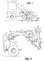
- a convertible bucket attachment 10 in accordance with the present invention is mounted to a front end loader 12 to be lifted and swung about a horizontal axis between loading and dumping positions as shown by a comparison of Figs. 1 and 2.
- the front end loader 12 is mounted on the chassis 13 of a tractor 14 and includes a pair of forwardly extending, laterally spaced apart lift arms 16 and 18 (a portion of the latter being visible in Fig. 8).
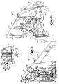
- the convertible bucket attachment 10 broadly includes three major components, i.e., a main transverse structural base 20 attached to the front ends of the loader arms 16,18, a clam 22 swingably attached to and carried by the base 20, and an angularly shiftable dozer blade 24 likewise mounted on the base 20, but independently of the clam 22.
- the clam 22 includes a generally rectangular floor 28, a pair of triangular, spaced-apart, upright, substantially parallel side walls 30 and 32 joined along their lower edges to opposite lateral extremities of the floor 28, and a transverse structural beam 36 (Fig. 4) interconnecting the side walls 30,32 across their upper rear ends.
- the tubular beam 36 forms the main torsional backbone of the clam 22.
- the side walls 30 and 32 lie in substantially vertical, parallel planes, while the beam 36 is parallel to the transverse axis about which the clam 22 swings relative to the base 20.
- the aforesaid swing axis is defined by aligned hinge pins 38 and 40 (Fig. 4) which respectively connect rearwardly extending lugs 42 and 44 on the beam 36 to the upper ends of a pair of upright mounting brackets 46 and 48 fixed to the back side of the base 20. In this manner the clam 22 is swingably supported by and coupled with the base 20.
- the floor 28 of the clam 22 is substantially planar and is provided with a front transverse scraping edge 50 extending between side walls 30 and 32. As illustrated in Figs. 6 and 7, the floor 28 along its rear margin is upturned to present an upwardly and rearwardly projecting, transversely extending abutment flange 52 which is configured to engage and bear against a lower front scraping knife 54 on the dozer blade 24 when the clam 22 is in its lowered position as in Fig. 6. As shown in Fig. 8, three fore-and-aft skid plates 60, 62 and 64 are affixed to the bottom of floor 28 to strengthen the latter. As shown in Figs.
- a pair of right and left, upright stiffening plates 66 and 68 are fixed to side walls 30,32 at their rear extremities, and fore-and-aft, downwardly inclined side cutter members 70,72 lead from the upper ends of the plates 66,68 to the lower front corners of the side walls 30,32. Gussets 34 provide additional strengthening between the side cutters 70,72 and floor 28.
- the clam 22 is raised and lowered about pivot pins 38,40 by an upright double acting hydraulic cylinder 74 on the rear of the base 20 (Figs. 3 and 4).
- a pair of side-by-side crank arms 76 and 78 extend normally rearwardly from beam 36 and have a pivot pin connection 80 with the head 82 of the extensible shaft 84 of the cylinder 74.
- the lower, anchor end of cylinder 74 is pivotally mounted to base 20 by pin 86.
- the mounting base 20 is transversely generally U-shaped (Figs. 4 and 8) in the nature of a wide structural channel member, presenting an upright flat bight 104 and a pair of upper and lower, longitudinal flanges 106,108 which project forwardly from bight 104.
- the clam mounting brackets 46,48 are fixed to the rear face of bight 104 and project upwardly beyond the upper flange 106 to provide operating clearance for the dozer blade 24 as will hereinafter be described in more detail.
- Upper holes 88 and lower holes 90 in the brackets 46,48 provide points of attachment of the base 20 to the loader 12. As shown in Fig.
- dump links 92 of the loader 12 are connected by pins 94 to holes 88, while lift arms 16,18 are connected by pins 96 to lower holes 90.
- a pair of upright, laterally spaced apart plates 100,102 are affixed to the back face of bight 104 centrally thereof to confine the hydraulic cylinder and to provide a mounting location for the cylinder mounting pin 86.
- the dozer blade 24 is mounted on the base 20 by coupling means located on the front side of the base 20 and denoted broadly by the numeral 109 in Figs. 4, 5, 6 and 8.
- the top flange 106 has a pair of mounting holes 110 and 112 adjacent the center of flange 106, while the lower flange 108 includes a pair of corresponding holes (not shown) positioned respectively therebeneath.
- Holes 110 and 112 receive, respectively, upright spindles 122 and 124, which serve to pivotally mount a pair of arms 126 and 128 of the mounting means 109 to the base 20.
- Suitable bearings 130 associated with the spindles 122,124 facilitate the horizontal swinging movement of the arms 126 and 128.
- Swinging of the arms 126 and 128 when the clam 22 has first been raised is controlled and effected by power mechanism in the nature of a pair of double-acting hydraulic cylinders 142 and 150 which lie horizontally along the front face of the base 20.
- Each of the arms 126 and 128 is provided with a pair of mounts 132 and 134 which receive a normally vertically oriented pivot pin 136 therethrough that is spaced a short distance from the corresponding spindle 122 or 124.
- Pin 136 extends through the head 138 of the shaft 140 of the corresponding cylinder 142 or 150 such that the cylinders 142 and 150 are connected to their respective arms 126 and 128 with relatively short moment arms.
- Each of the cylinders 142,150 is pivotally attached at its anchor end to the front face of the bight 104 by its own pair of vertically spaced mounting ears 114 and vertical pivot pin 120, located generally adjacent opposite ends of the base 20.
- the cylinders 142,150 are operable to swing the arms 126 and 128 between a folded-in position as illustrated by the arm 126 in Figs. 5 and 8, and folded-out position as illustrated by the arm 128 in the same figures.
- Arms 126 and 128 are generally channel-shaped to present upper and lower flat edges 152 and 154 which are interconnected by a slightly concave main body portion 156 as shown in Figs. 6 and 8. Such configuration provides structural strength as well as clearance for the transverse cylinders 142,150 when the arms 126,128 are folded in.
- each of the lost motion connections 155,157 includes an upright guide rod 158 adjacent the outer end of the respective arm 126,128 which spans the opposite edges 152,154 and projects a short distance beyond each of edges 152,154.
- each rod 158 are received within corresponding upper and lower guide slots 160 and 162 in a pair of vertically spaced, horizontal guide plates 164 and 166 on the back side of the dozer blade 24.
- the distance along the blade 24 between the outer ends of the slots 160 is substantially the same as the distance between the rods 158 when arms 126,128 are fully folded in.
- the blade 24 must also be retracted into a centered, squared-up position when the arms 126,128 are folded in.
- the distance between the inner ends of the slots 160 along the blade 24 is substantially the same as the distance between the rods 158 when one of the arms 126 or 128 is swung out and the other remains folded-in (as in Figs. 5 and 8). Consequently, the blade 24 must also be held in either a right or left side-shifted, angled attitude at that time, depending upon which arm is folded in and which is swung out.
- the dozer blade 24 itself is of generally box-like construction (Figs. 4,6 and 8) with a closed top 168, closed bottom 170, closed front 172, closed ends 174,176, but an open back.
- the front 172 is slightly concave, and the open nature of the back permits the base 20, arms 126,128 and the transverse cylinders 142,150 all to be nested neatly within the hollow blade 24 when the attachment 10 is in its bucket configuration as in Figs. 4 and 6 for example. It will also be noted as shown in Fig.
- the stiffening side plates 66,68 of the clam 22 partially rearwardly overlap the opposite ends 174,176 of the dozer blade 24 to rigidify the bucket and preclude lateral displacement of the blade.
- the blade 24 is trapped front-to-rear at this time by the upturned flange 52 of clam 22 and the base 20, and side-to-side by the stiffening side plates 66 and 68.
- One exemplary loader useful in connection with the present invention is a Bobcat 2400 Loader available from the Melroe Company of Fargo, North Dakota.
- the front end loader includes lift cylinders 184 for raising loader arms 16,18, and also tilt cylinders 186 mounted to the loader arms 16,18 and connected to links 92. Links 92 and tilt cylinders 186 are additionally connected to loader arms 16,18 by bail 188, as seen in Fig. 2.
- the front end loader 12 naturally includes a hydraulic pump (not shown) which is connected to the various hydraulic cylinders (all of which are double-acting) by conduits 190. Controls (not shown) are provided in the cab 192 of tractor 14 so the operator can not only operate the attachment 10 in the usual way from the tractor seat, but can also convert quickly between bucket and dozer configurations.
- the convertible bucket attachment 10 is mounted on the loader arms 16,18 in the manner illustrated in Figs. 1 and 2 in lieu of conventional buckets or dozer blade assemblies.
- the material which is resting on the ground or other supporting surface may be loaded into the bucket attachment 10 in the usual way by driving the vehicle forward and passing the scraping edge 50 of the bucket 10 under the material to be lifted.
- Lift cylinders 184 are then extended to raise the loader arms 16,18 and thereby raise the bucket 10 off the ground.
- the convertible bucket attachment 10 hereof may be tilted to drop the material collected therein at the desired location by extending tilt cylinder 186 to pivot bale 188. In so doing, the entire attachment 10 tilts, including base 20, clam 22 and dozer blade 24.
- the clam 22 In order to prepare the dozer blade 24 for dozing operations, the clam 22 must first be swung into a raised position as illustrated in Fig. 3 to expose the dozer blade 24. This is accomplished by actuating double-acting hydraulic cylinder 74 to retract shaft 84 and thus bring head 82 down toward cylinder 74. Once the clam 22 is raised, the dozer blade 24 may be left in its centered, straight-forward position if desired and used to push materials straight ahead when the tractor is advanced.
- the dozer blade 24 is also released for either right or left side-shifting and angle displacement if such is desired for the particular job at hand.
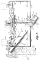
- the dozer blade 24 has been shifted and angled to the right (as viewed from the rear of the machine), although it is to be understood that the blade 24 could just as easily have been shifted and angle-adjusted to the left.
- the guide rod 158 of lost motion connection 155 slides toward the inner end of the slot 160 until it can go no further. Further outward swinging of the swing arm 128 thus has the effect not only of pushing the left end of the dozer blade 24 outwardly, but also of displacing the blade 24 in a rightward direction along its own longitudinal axis until the rod 158 of the other lost motion connection 157 bottoms out at the inner end of its slot 160. Consequently, as shown most clearly in Fig. 5, even though the blade 24 started out fully within the lateral boundries defined by the opposite side walls 30 and 32 of the clam 22, in its final side-shifted and angle adjusted position the blade 24 has its right end projected laterally outwardly beyond the corresponding right side wall 30 of the clam 22.
- the operator may simply release the control valve or otherwise move it to a position which hydraulically locks the cylinder 142 in its extended state while the cylinder 150 is also locked in its retracted state, thus rigidly and securely holding the blade 24 in its side-shifted, angled position.
- the vehicle With the dozer blade 24 in this position, the vehicle is ideally suited for windrowing loose materials which are scattered on the ground, or for backfilling a ditch such as the ditch 194 illustrated in Fig. 5.
- a ditch such as the ditch 194 illustrated in Fig. 5.
- the dozer blade 24 simply diverts and rolls the spoil 196 smoothly and continuously into the ditch as the vehicle continues to advance. Because of the laterally projected condition of the dozer blade 24, the front wheel 180 of the tractor can be maintained at a safe distance from the sides of the ditch to guard against the risk of cave in.
- the operator has an excellent view of the soil as it rolls into the ditch so that he may react quickly to any steering adjustments that may become necessary as the backfilling operation is carried out.
- the rod 158 of the lost motion connection 155 slides to the outer end of slot 160 such that further inward swinging of the arm 128 has the effect of pulling the dozer blade 24 laterally inwardly at the same time it is being swung back toward the squared up position.
- Such pulling action by the inwardly swinging arm 128 on the left end of the dozer blade 24 also causes the rod 158 of lost motion assembly 157 at the right end of the blade 24 to slide to the outer end of its slot 160 until rod 158 can go no further.
- the cylinder 142 will be fully retracted and both of the rods 158 will have been shifted to the outermost ends of their respective guide slots 160.
- Extension of the clam cylinder 74 then lowers the clam 22 into clamping position against the dozer blade 24 to reestablish the loading bucket configuration.
Landscapes
- Engineering & Computer Science (AREA)
- Mechanical Engineering (AREA)
- Mining & Mineral Resources (AREA)
- Civil Engineering (AREA)
- General Engineering & Computer Science (AREA)
- Structural Engineering (AREA)
- Operation Control Of Excavators (AREA)
- Forklifts And Lifting Vehicles (AREA)
- Shovels (AREA)
Claims (22)
- Ladervorrichtung (10), umfassend:eine Schieberplatte (24);einen Greifer mit einem Paar gegenüberliegender, aufrechterSeitenwände (30, 32) und einem Boden (28) zwischen den Seitenwänden;Mittel zum Befestigen des Greifers (22) zur Bewegung zwischen einer gesenkten Stellung, in der der Greifer (22) mit der Schieberplatte (24) zusammenwirkt, um eine Ladewanne zu ergeben, in welcher die Schieberplatte (24) die Rückwand der Wanne und der Greifer (22) die gegenüberliegenden Seiten und den Boden (28) der Wanne bilden, und einer angehobenen Stellung, in der der Greifer (22) die Schieberplatte (24) für Schubarbeiten exponiert; undMittel zur Befestigung der Schieberplatte (24) zum Verschieben der Schieberplatte (24) unabhängig von dem Greifer (22), wenn der Greifer (22) sich in der angehobenen Stellung befindet, wobei der Verschiebevorgang zwischen einer mittleren, gerade ausgerichteten Stellung und linken oder rechten, seitlich verschobenen, schiefwinkeligen Stellungen stattfindet, bei denen die Schieberplatte (24) seitlich von der mittleren Stellung versetzt und in einem Winkel im Verhältnis zur normalen Bewegungsrichtung der Ladervorrichtung (10) im Gebrauch angeordnet ist.
- Ladervorrichtung (10) gemäß Anspruch 1,wobei der Greifer (22) und die Schieberplatte (24) von einem gemeinsamen Basiselement gehalten werden, wobei das Mittel zur Befestigung des Greifers (22) ein erstes Verbindungsstück zwischen dem Greifer (22) und dem Basiselement (20) und Kraftmittel zum Anheben und Senken des Greifers im Verhältnis zum Basiselement (20) aufweist;wobei das Mittel zur Befestigung der Schieberplatte (24) ein zweites Verbindungsstück zwischen der Schieberplatte (24) und dem Basiselement und einen Kraftmechanismus zum seitlichen Verschieben der Schieberplatte (24) und Schrägstellung derselben im Verhältnis zum Basiselement (20) aufweist.
- Ladervorrichtung (10) gemäß Anspruch 2,
wobei das erste Verbindungsstück ein quer angeordnetes, horizontales Gelenk zwischen dem Greifer (22) und dem Basiselement (20) aufweist. - Ladervorrichtung (10) gemäß Anspruch 2,wobei das zweite Verbindungsstück ein Paar Arme (16, 18) aufweist, die jeweils an einer Innenseite mit dem Basiselement (20) schwenkbar verbunden sind, um eine horizontale Schwenkbewegung zwischen eingezogenen Stellungen, die sich quer zum normalen Arbeitsweg der Vorrichtung (10) erstrecken, und ausgefahrenen Stellungen, die sich im allgemeinen längs des Arbeitswegs der Vorrichtung (10) erstrecken, ausführen zu können;wobei das zweite Verbindungsstück des weiteren Totgangverbindungen zwischen den äußeren Enden der Arme und der Schieberplatte (24) aufweist, wobei jede der Totgangverbindungen ein vertikales Gelenk umfaßt, welches während des Verschiebens der Schieberplatte (24) entlang der Schieberplatte (24) durch einen beschränkten Totgangsbereich versetzbar ist;wobei der Kraftmechanismus eine getrennte Kraftvorrichtung für jeden der Arme aufweist, die jeweils so betätigt werden können, daß beide Arme eingezogen gehalten werden, wenn sich die Schieberplatte (24) in der mittleren, gerade ausgerichteten Stellung befindet, daß ein Arm eingezogen und der andere Arm ausgefahren werden können, wenn sich die Schieberplatte (24) in der links seitlich versetzten, schiefwinkeligen Stellung befindet, und daß ein Arm ausgefahren und der andere Arm eingezogen werden können, wenn sich die Schieberplatte (24) in ihrer rechten, seitlich versetzten, schiefwinkeligen Stellung befindet.
- Ladervorrichtung gemäß Anspruch 2,
wobei der Greifer (22) so angeordnet ist, daß er die Schieberplatte gegen das Basiselement klemmt, wenn sich der Greifer (22) in seiner gesenkten Stellung befindet, wobei im Zusammenwirken mit der Schieberplatte eine Ladewanne geschaffen wird. - Ladervorrichtung gemäß Anspruch 5,
wobei die Seitenwände des Greifers (22) mit einer darauf angeordneten Beschränkungsstruktur versehen sind, um die gegenüberliegenden Seitenenden der Schieberplatte (24) zu überlappen, wenn der Greifer mit der Schieberplatte (24) zusammenwirkt, um eine Ladewanne zu bilden, wodurch das seitliche Versetzen der Schieberplatte (24) eingeschränkt wird. - Ladervorrichtung gemäß Anspruch 2,
wobei die Seitenwände des Greifers (22) mit einer darauf angeordneten Beschränkungsstruktur versehen sind, um die gegenüberliegenden Seitenenden der Schieberplatte (24) zu überlappen, wenn der Greifer (22) mit der Schieberplatte (24) zusammenwirkt, um eine Ladewanne zu bilden, wodurch das seitliche Versetzen der Schieberplatte (24) eingeschränkt wird. - Mehrzweckfahrzeug zur Materialbearbeitung mit einem beweglichen Fahrgestell, das eine Ladervorrichtung gemäß einem der Ansprüche 1 bis 7 benützt, umfassend:ein Paar seitlich beabstandete, kraftbetriebene Hebearme, die auf dem Fahrgestell schwenkbar für Auf- und Abbewegung zum Heben und Senken befestigt sind;ein starres Basiselement (20), das sich quer zwischen den Hebearmen erstreckt und an diesen befestigt ist, um mit den Hebearmen während deren Hebe- und Senkbewegungen bewegt zu werden;die vor diesem Basiselement getragene Schieberplatte (24);einen Greifer (22) mit einem Paar gegenüberliegender, aufrechter Seitenwände und einem sich zwischen den Seitenwänden erstreckenden Boden;Mittel, mit denen der Greifer (22) schwenkbar am Basiselement (20) befestigt ist, für die Bewegung zwischen einer gesenkten Stellung, in der der Greifer (22) mit der Schieberplatte (24) zusammenwirkt, um eine Ladewanne zu ergeben, in welcher die Schieberplatte die Rückwand der Wanne und der Greifer (22) die gegenüberliegenden Seiten und den Boden (28) der Wanne bilden, und einer angehobenen Stellung, in der der Greifer (22) die Schieberplatte (24) für Schubarbeiten exponiert; undMittel, mit denen die Schieberplatte (24) verschiebbar an dem Basiselement befestigt ist, um die Schieberplatte (24) unabhängig von dem Greifer (22) verschieben zu können, wenn der Greifer (22) sich in der angehobenen Stellung befindet, wobei der Verschiebevorgang zwischen einer mittleren, gerade ausgerichteten Stellung und rechten oder linken, seitlich verschobenen, schiefwinkeligen Stellungen stattfindet, bei denen die Schieberplatte (24) seitlich von der mittleren Stellung versetzt und in einem schiefen Winkel zur normalen Bewegungsrichtung des Fahrzeugs angeordnet ist
- Mehrzweckfahrzeug gemäß Anspruch 8,wobei das Befestigungsmittel für den Greifer (22) ein erstes Verbindungsstück zwischen dem Greifer (22) und dem Basiselement (20) und doppeltwirkende Flüssigkeitsdruck-Kraftmittel zum Schwenken des Greifers (22) zwischen seiner angehobenen und seiner gesenkten Stellung um das erste Verbindungsstück herum aufweist;wobei das Mittel zur Befestigung der Schieberplatte (24) ein zweites Verbindungsstück zwischen der Schieberplatte (24) und dem Basiselement (20) und einen doppeltwirkenden Flüssigkeitsdruck-Mechansimus zum seitlichen Verschieben der Schieberplatte (24) und Schrägstellung derselben im Verhältnis zum Basiselement (20) aufweist.
- Mehrzweckfahrzeug gemäß Anspruch 9,
wobei das erste Verbindungsstück ein quer angeordnetes, horizontales Gelenk zwischen dem Greifer (22) und dem Basiselement (20) aufweist. - Mehrzweckfahrzeug gemäß Anspruch 9,wobei das zweite Verbindungsstück ein Paar Arme aufweist, die jeweils an einer Innenseite mit dem Basiselement (20) schwenkbar verbunden sind, um eine horizontale Schwenkbewegung zwischen eingezogenen Stellungen, die sich quer zum normalen Arbeitsweg der Vorrichtung erstrecken, und ausgefahrenen Stellungen, die sich im allgemeinen längs des Arbeitswegs der Vorrichtung erstrecken, ausführen zu können;wobei das zweite Verbindungsstück des weiteren Totgangverbindungen zwischen den äußeren Enden der Arme und der Schieberplatte (24) aufweist, wobei jede der Totgangverbindungen ein vertikales Gelenk umfaßt, welches während des Verschiebens der Schieberplatte (24) entlang der Schieberplatte (24) durch einen beschränkten Totgangsbereich versetzbar ist;wobei der Kraftmechanismus eine getrennte Kraftvorrichtung für jeden der Arme aufweist, die jeweils so betätigt werden können, daß beide Arme eingezogen gehalten werden, wenn sich die Schieberplatte (24) in der mittleren, gerade ausgerichteten Stellung befindet, daß ein Arm eingezogen und der andere Arm ausgefahren werden können, wenn sich die Schieberplatte (24) in der links seitlich versetzten, schiefwinkeligen Stellung befindet, und daß ein Arm ausgefahren und der andere Arm eingezogen werden können, wenn sich die Schieberplatte (24) in ihrer rechten, seitlich versetzten, schiefwinkeligen Stellung befindet.
- Mehrzweckfahrzeug gemäß Anspruch 8,
wobei der Greifer (22) so angeordnet ist, daß er die Schieberplatte (24) gegen das Basiselement (20) klemmt, wenn sich der Greifer in seiner gesenkten Stellung befindet, wobei im Zusammenwirken mit der Schieberplatte eine Ladewanne geschaffen wird. - Mehrzweckfahrzeug gemäß Anspruch 12,
wobei die Seitenwände des Greifers (22) mit einer darauf angeordneten Beschränkungsstruktur versehen sind, um die gegenüberliegenden Seitenenden der Schieberplatte (24) zu überlappen, wenn der Greifer mit der Schieberplatte (24) zusammenwirkt, um eine Ladewanne zu bilden, wodurch das seitliche Versetzen der Schieberplatte (24) eingeschränkt wird. - Mehrzweckfahrzeug gemäß Anspruch 8,
wobei die Seitenwände des Greifers (22) mit einer darauf angeordneten Beschränkungsstruktur versehen sind, um die gegenüberliegenden Seitenenden der Schieberplatte (24) zu überlappen, wenn der Greifer mit der Schieberplatte (24) zusammenwirkt, um eine Ladewanne zu bilden, wodurch das seitliche Versetzen der Schieberplatte (24) eingeschränkt wird. - Ladervorrichtung (10) gemäß Anspruch 1, umfassend:ein quer angeordnetes, starres Basiselement (20) mit einer Vorder- und einer Rückseite bezüglich des normalen Arbeitswegs der Ladervorrichtung (10) während des Gebrauchs, wobei das Basiselement (20) mit einem Paar Befestigungsklammern auf der Rückseite desselben versehen ist, die dazu verwendet werden können, das Basiselement (20) an den Hebearmen des Laders zu befestigen;ein schwenkbares Befestigungsmittel, das aus dem Basiselement nach oben herausragt und mit dem Greifer (22) an einer oberhalb des Basiselements beabstandeten Stelle verbunden ist, um die Auf- und Abschwenkbewegung des Greifers (22) über die Vorderseite des Basiselements (20) um eine Querachse zwischen angehobener und gesenkter Stellung zu ermöglichen;doppeltwirkende, hydraulische Kraftmittel an der Rückseite des Basiselements (20), die zwischen dem Basiselement (20) und dem Greifer (22) verbunden sind, um eine kraftbetriebene Schwenkbewegung des Greifers (22) zwischen seinen angehobenen und gesenkten Stellungen zu ermöglichen;ein Paar Schwenkarme an der Vorderseite des Basiselements (20) bezüglich der normalen Arbeitsrichtung der Ladervorrichtung (10);wobei jeder der Schwenkarme an einer seiner Innenseiten mit dem Basiselement schwenkbar verbunden ist, um eine horizontale Schwenkbewegung zwischen eingezogenen Stellungen, bei denen die Arme sich quer zum normalen Arbeitsweg der Vorrichtung erstrecken, und ausgefahrenen Stellungen, bei denen die Arme sich im allgemeinen längs des Arbeitswegs der Vorrichtung erstrecken, ausführen zu können;getrennte, unabhängig betätigbare, doppeltwirkende Flüssigkeitskraftvorrichtungen an der Vorderseite des Basiselements (20), die in Arbeitsverbindung zwischen dem Basiselement (20) und einem dazugehörenden Schwenkarm stehen, um eine kraftbetriebene Schwenkbewegung der Schwenkarme unabhängig voneinander zwischen den eingezogenen und ausgefahrenen Stellungen zu bewirken;die von den Schwenkarmen an deren äußeren Enden getragene Schieberplatte (24); undein Paar Totgangverbindungen zwischen den Außenenden der Arme und der Schieberplatte (24), im allgemeinen angrenzend an die gegenüberliegenden seitlichen Enden der Schieberplatte (24);wobei der Greifer (22), wenn er sich in seiner gesenkten Stellung befindet, mit der Schieberplatte (24) zusammenwirkt, um eine Ladewanne zu schaffen, in der die Schieberplatte (24) die Rückwand der Wanne und der Greifer (22) die gegenüberliegenden Seiten und den Boden der Wanne bildet;wobei der Greifer (22), wenn er sich in seiner angehobenen Stellung befindet, so angeordnet ist, daß er die Schieberplatte (24) für Schubarbeiten und für die Anpassung des Seitenversetzungswinkels exponiert;wobei das getrennte Kraftmittel durch die Schwenkarme betätigt werden kann, wenn der Greifer (22) sich in seiner angehobenen Stellung befindet, um die Schieberplatte (24) zwischen einer mittleren, gerade ausgerichteten Stellung und einer rechten oder linken, seitlich verschobenen, schiefwinkeligen Stellung zu verschieben, in der die Schieberplatte (24) seitlich von der mittleren Stellung versetzt und in einem schiefen Winkel im Verhältnis zum normalen Arbeitsweg der Vorrichtung (10) angeordnet ist;wobei die getrennten Kraftvorrichtungen so betätigt werden können, daß beide Arme eingezogen gehalten werden, wenn sich die Schieberplatte (24) in ihrer mittleren, gerade ausgerichteten Stellung befindet, daß ein Arm eingezogen und der andere Arm ausgefahren werden kann, wenn sich die Schieberplatte (24) in ihrer linken, seitlich versetzten, schiefwinkeligen Stellung befindet, und daß ein Arm ausgefahren und der andere Arm eingezogen werden kann, wenn sich die Schieberplatte in ihrer rechten, seitlich versetzten, schiefwinkeligen Stellung befindet,wobei jede der Totgangverbindungen ein vertikales Gelenk aufweist, das während der Anpassung des Seitenversetzungswinkels der Schieberplatte (24) entlang der Schieberplatte (24) einen beschränkten Totgangweg versetzt werden kann.
- Ladervorrichtung (10) gemäß Anspruch 1 oder 2,wobei der Greifer (22) einen Boden aufweist, der sich zwischen einem Paar einander gegenüberliegender, beabstandeter, sich im wesentlichen vertikal erstreckender Seitenwände erstreckt und mit denselben verbunden ist;wobei die Schieberplatte (24) ein erstes und ein zweites beabstandetes Ende aufweist und derart bemessen ist, daß die beabstandeten Enden zwischen den Seitenwänden des Greifers (22) angeordnet werden können;wobei mit dem Greifer und der Schieberplatte (24) ein Hauptrahmen operativ verbunden ist, der ein Mittel zum Verschieben des Greifers (22) in einer vertikalen Ebene zwischen einer ersten Stellung, in der die Schieberplatte (24) zwischen den Seitenwänden und dem angrenzenden Boden des Greifers (22) angeordnet ist, und einer zweiten Stellung, in der der Greifer in vertikal beabstandetem Verhältnis oberhalb der Schieberplatte (24) angeordnet ist; undein mit dem Hauptrahmen verbundenes Mittel zum Verschieben der Schieberplatte (24) unabhängig vom Greifer (22) zwischen einer ersten Stellung, in der die Schieberplatte (24) im wesentlichen normal zur beabsichtigten Bewegungsrichtung steht und seitlich innerhalb vertikaler, von den Seitenwänden begrenzter Ebenen angeordnet ist, und einer zweiten Stellung, in der die Schieberplatte (24) im schiefen Winkel im Verhältnis zu ihrer beabsichtigten Bewegungsrichtung angeordnet ist und zumindest ein Teil der Schieberplatte (24) seitlich außenbords einer der vertikalen Ebenen verschoben wird, wenn der Greifer (22) in dem vertikal beabstandetem Verhältnis oberhalb der Schieberplatte (24) angeordnet ist.
- Ladervorrichtung (10) gemäß Anspruch 16, wobei die Seiten des Greifers (22) im wesentlichen parallel sind.
- Ladervorrichtung (10) gemäß Anspruch 16, wobei die Schieberplatte (24) zusammenwirkend mit dem Greifer (22) konfiguriert ist, um mit dem Greifer (22) so angeordnet zu werden, daß eine Rückwand desselben begrenzt wird.
- Ladervorrichtung (10) gemäß Anspruch 16, wobei das Mittel zum vertikalen Verschieben des Greifers (22) eine Struktur umfaßt, mit der der Greifer (22) schwenkbar am Hauptrahmen befestigt wird.
- Ladervorrichtung (10) gemäß Anspruch 19, wobei das Mittel zum vertikalen Verschieben des Greifers (22) einen Hydraulikzylinder aufweist, der einen erweiterbaren Arm hervorbringt, welcher den Hauptrahmen und den Greifer (22) operativ verbindet, um den Greifer (22) im Verhältnis zum Hauptrahmen zu schwenken.
- Ladervorrichtung (10) gemäß Anspruch 16, wobei das Mittel zum Verschieben ein Mittel zur Einrichtung der Schieberplatte (24) in einem Winkel aufweist, um das erste Ende bezüglich der Richtung des Arbeitswegs vor dem zweiten Ende anzuordnen und als Alternative zur Einrichtung der Schieberplatte (24) in einem Winkel, um das zweite Ende bezüglich der Richtung des beabsichtigten Arbeitswegs vor dem ersten Ende anzuordnen.
- Ladervorrichtung (10) gemäß Anspruch 21, wobei das Mittel zur Winkeleinrichtung einen ersten und einen zweiten Arm aufweist, deren eine Enden mit dem Hauptrahmen schwenkbar verbunden sind und deren gegenüberliegende Enden mit der Schieberplatte an vorher festgelegten Befestigungsschlitzen auf der Schieberplatte (24) angrenzend an ihre jeweiligen Enden schwenkbar verbunden sind, um ein beschränktes seitliches Verschieben der Schieberplatte (24) im Verhältnis zu den Armen zu ermöglichen, und des weiteren Antriebsmittel, die jeweils schwenkbar mit dem ersten und dem zweiten Arm und mit dem Hauptrahmen verbunden sind, wobei die Antriebsmittel gegen die Schieberplatte (24) verlängerbar sind, und die Schieberplatte im Verhältnis zum Hauptrahmen in einem Winkel einzurichten und gleichzeitig die Schieberplatte (24) seitlich zu verschieben.
Applications Claiming Priority (3)
| Application Number | Priority Date | Filing Date | Title |
|---|---|---|---|
| US07/841,586 US5165191A (en) | 1992-02-25 | 1992-02-25 | Front end loader attachment convertible between loading bucket and side-shift-angle dozer configurations |
| US841586 | 1992-02-25 | ||
| PCT/US1993/001305 WO1993017190A1 (en) | 1992-02-25 | 1993-02-12 | Front end loader attachment convertible between loading bucket and side-shift-angle dozer configurations |
Publications (3)
| Publication Number | Publication Date |
|---|---|
| EP0627033A1 EP0627033A1 (de) | 1994-12-07 |
| EP0627033A4 EP0627033A4 (en) | 1997-01-02 |
| EP0627033B1 true EP0627033B1 (de) | 1999-11-17 |
Family
ID=25285240
Family Applications (1)
| Application Number | Title | Priority Date | Filing Date |
|---|---|---|---|
| EP93905048A Expired - Lifetime EP0627033B1 (de) | 1992-02-25 | 1993-02-12 | Wahlweise in eine ladeschaufel oder ein seitenwinkeleinstellbares planierschild unwandelbare ladevorrichtung |
Country Status (5)
| Country | Link |
|---|---|
| US (1) | US5165191A (de) |
| EP (1) | EP0627033B1 (de) |
| CA (1) | CA2130916C (de) |
| DE (1) | DE69327048T2 (de) |
| WO (1) | WO1993017190A1 (de) |
Families Citing this family (32)
| Publication number | Priority date | Publication date | Assignee | Title |
|---|---|---|---|---|
| US5538086A (en) * | 1994-12-27 | 1996-07-23 | Wright; Rocky A. | Variable orientation attachment implement |
| US5562398A (en) * | 1995-01-05 | 1996-10-08 | Knutson; Kenneth | Skid steer loader tiltable attachment |
| US5638618A (en) * | 1996-06-07 | 1997-06-17 | Blizzard Corporation | Adjustable wing plow |
| US5899007A (en) * | 1996-06-07 | 1999-05-04 | Blizzard Corporation | Adjustable wing plow |
| US6035944A (en) * | 1998-05-27 | 2000-03-14 | M. J. Electric, Inc. | Hinged plow attachment for wheeled and tracked vehicles |
| KR100559232B1 (ko) * | 1998-09-30 | 2006-05-25 | 볼보 컨스트럭션 이키프먼트 홀딩 스웨덴 에이비 | 다기능형 건설장비 |
| US6230424B1 (en) | 1998-12-08 | 2001-05-15 | Caterpillar Inc. | Base edge protection assembly for an implement of a work machine |
| GB2341167B (en) * | 1999-01-25 | 2000-07-19 | David Douglas Cook | Quick hitch dozer blade to mount on tracked or wheeled 360 degree hydraulic excavator |
| US6109363A (en) * | 1999-05-28 | 2000-08-29 | Caterpillar S.A.R.L. | Blade assembly with angular movement capability |
| US6167642B1 (en) | 1999-06-23 | 2001-01-02 | Mark A. Nardini | Tractor bucket extension device and method |
| US6493967B2 (en) | 2000-05-26 | 2002-12-17 | Frederick J. Holmes | Apparatus for attaching an accessory to an excavator |
| CN1462327A (zh) * | 2000-09-22 | 2003-12-17 | 戴维·凯尔文·弗格森 | 运土刮铲附件 |
| US6408549B1 (en) | 2000-10-12 | 2002-06-25 | Blizzard Corporation | Adjustable wing plow |
| US6412199B1 (en) | 2000-10-12 | 2002-07-02 | Blizzard Corporation | Adjustable wing plow with fixed pivot |
| US6442877B1 (en) | 2000-10-12 | 2002-09-03 | Blizzard Corporation | Plow with rear mounted, adjustable wing |
| US7134227B2 (en) * | 2003-05-02 | 2006-11-14 | Douglas Dynamics, L.L.C. | Adjustable wing plow |
| US20050079014A1 (en) * | 2003-10-10 | 2005-04-14 | Dick's Asphalt Services Of Kankakee, Inc. | Blade implement and method of use |
| KR100606506B1 (ko) * | 2004-05-21 | 2006-08-02 | 주일환 | 굴삭 및 로딩 기능을 갖는 건설장비 |
| US7681337B2 (en) * | 2005-10-21 | 2010-03-23 | Batesville Services, Inc. | Plow with blade wing |
| US20070089327A1 (en) * | 2005-10-21 | 2007-04-26 | Watson Gary E | Plow with blade wing |
| US8660738B2 (en) * | 2010-12-14 | 2014-02-25 | Catepillar Inc. | Equipment performance monitoring system and method |
| US8607482B2 (en) | 2011-02-28 | 2013-12-17 | Douglas Dynamics, L.L.C. | Plow with pivoting blade wing(s) |
| US8418777B1 (en) * | 2011-12-09 | 2013-04-16 | GK Machine, Inc. | Agricultural folding scraper blade |
| US8887413B2 (en) | 2012-02-13 | 2014-11-18 | Thomas Andrew Miller | Expanding material box for equipment |
| US8850724B2 (en) | 2013-02-15 | 2014-10-07 | Douglas Dynamics, L.L.C. | Plow with pivoting blade wing |
| KR101801651B1 (ko) | 2015-11-09 | 2017-11-27 | 대호 (주) | 아웃트리거를 포함하는 도저 |
| KR102281473B1 (ko) * | 2015-11-09 | 2021-07-26 | 대호 (주) | 아웃트리거가 구비된 도저 |
| US12146292B2 (en) * | 2019-07-11 | 2024-11-19 | Rose Welding & Crane Service, Inc. | Reconfigurable box blade |
| FR3110184B1 (fr) * | 2020-05-15 | 2022-07-08 | Rideau Manutention Access Riman | Dispositif de manutention pour engin de manutention de charge et engin équipé d'un tel dispositif |
| US12522999B2 (en) * | 2020-09-18 | 2026-01-13 | Great Plains Manufacturing, Inc. | Multipurpose bucket |
| CN112609759B (zh) * | 2020-11-05 | 2023-04-25 | 北方魏家峁煤电有限责任公司 | 一种防砸装置及推土机 |
| US12584287B2 (en) | 2023-11-02 | 2026-03-24 | Deere & Company | Reconfigurable grading blade attachment with a stabilizer wheel assembly on a work machine |
Family Cites Families (18)
| Publication number | Priority date | Publication date | Assignee | Title |
|---|---|---|---|---|
| US2824391A (en) * | 1953-11-13 | 1958-02-25 | Leo C Krazinski | Shovel attachment for bulldozers |
| US2812595A (en) * | 1954-01-15 | 1957-11-12 | Drott Mfg Corp | Earth moving apparatus |
| US2768760A (en) * | 1955-02-21 | 1956-10-30 | John S Pilch | Material handling device for tractor mounted loaders |
| US3071793A (en) * | 1959-05-04 | 1963-01-08 | Le Grand H Lull | Street maintenance equipment |
| US2967364A (en) * | 1959-10-23 | 1961-01-10 | Caterpillar Tractor Co | Bulldozer blade support and angling adjustment |
| US3077999A (en) * | 1960-04-27 | 1963-02-19 | Caterpillar Tractor Co | Multi-purpose loader bucket |
| CH404564A (it) * | 1964-09-02 | 1965-12-15 | Beltrami Osmano | Benna per macchina scavatrice |
| US3243067A (en) * | 1965-03-22 | 1966-03-29 | Int Harvester Co | Loader for tractor mounting |
| US3344454A (en) * | 1966-02-18 | 1967-10-03 | Mikalson Severine Albert | Remote controlled window washer for high rise buildings |
| US3539022A (en) * | 1968-01-02 | 1970-11-10 | Allis Chalmers Mfg Co | Earthmoving attachment mounting |
| US3591935A (en) * | 1968-07-22 | 1971-07-13 | Mark H Bremmer | Earth moving equipment |
| US3559314A (en) * | 1968-09-16 | 1971-02-02 | John H Funk | Bucket attachment for bulldozer blades and the like |
| US3759110A (en) * | 1972-01-10 | 1973-09-18 | Case Co J I | Hydraulic angle dozer |
| US4566844A (en) * | 1982-12-21 | 1986-01-28 | Campin Joseph C | Bucket for material |
| US4633601A (en) * | 1984-09-25 | 1987-01-06 | Esco Corporation | Excavating shovel |
| US4854811A (en) * | 1987-06-05 | 1989-08-08 | Veys Jeff M | Bucket-blade attachment for tractors |
| US4974350A (en) * | 1988-02-01 | 1990-12-04 | Puckett Juan E | Blade/scoop unit for bulldozer |
| US4890400A (en) * | 1988-10-27 | 1990-01-02 | Long Jeffrey D | Bucket attachment for tractor blade |
-
1992
- 1992-02-25 US US07/841,586 patent/US5165191A/en not_active Expired - Fee Related
-
1993
- 1993-02-12 WO PCT/US1993/001305 patent/WO1993017190A1/en not_active Ceased
- 1993-02-12 DE DE69327048T patent/DE69327048T2/de not_active Expired - Fee Related
- 1993-02-12 CA CA002130916A patent/CA2130916C/en not_active Expired - Fee Related
- 1993-02-12 EP EP93905048A patent/EP0627033B1/de not_active Expired - Lifetime
Also Published As
| Publication number | Publication date |
|---|---|
| DE69327048D1 (de) | 1999-12-23 |
| WO1993017190A1 (en) | 1993-09-02 |
| DE69327048T2 (de) | 2000-07-13 |
| EP0627033A1 (de) | 1994-12-07 |
| EP0627033A4 (en) | 1997-01-02 |
| CA2130916A1 (en) | 1993-09-02 |
| CA2130916C (en) | 1998-08-18 |
| US5165191A (en) | 1992-11-24 |
Similar Documents
| Publication | Publication Date | Title |
|---|---|---|
| EP0627033B1 (de) | Wahlweise in eine ladeschaufel oder ein seitenwinkeleinstellbares planierschild unwandelbare ladevorrichtung | |
| US5564885A (en) | Multipurpose work attachment for a front end loader | |
| US6347670B1 (en) | Earth moving scraper | |
| US4999022A (en) | Bucket-blade attachment for tractors | |
| US6499934B1 (en) | Implement attachment bracket for skid steer loader mounting plate | |
| US4907356A (en) | Slipper bucket for grapple | |
| US4859130A (en) | Material handling attachment for a tractor having a multiple-point hitch assembly | |
| US5599158A (en) | Linkage arrangement for a wheel loader | |
| US5367796A (en) | Multitote carrier for excavator | |
| US6126216A (en) | Bucket attachment for log grapple | |
| US5156215A (en) | Counterweight assembly for crawler tractor | |
| US4545721A (en) | Combined lift fork and bucket device for attachment to a vehicle | |
| US4854811A (en) | Bucket-blade attachment for tractors | |
| US6776571B2 (en) | Fork attachment for backhoe | |
| US20020066215A1 (en) | Swivel mounting for quick attachment bracket | |
| US4808061A (en) | Single arm backhoe | |
| US4640662A (en) | Fork lift attachment for tractor | |
| EP0538439A1 (de) | Tragvorrichtung für Erdbearbeitungsgerät | |
| US3977548A (en) | Cylinder attachment means for an excavator and method for using the same | |
| US4444542A (en) | Vehicle with double booms | |
| US3892322A (en) | Scraper and digger attachment for a tractor loader | |
| US4753568A (en) | Material handling attachment for a tractor having a multiple-point hitch assembly | |
| US5176491A (en) | Overcenter backhoe apparatus | |
| US20060243465A1 (en) | Material handling system | |
| US11447925B2 (en) | Retrofittable conversion tine system for bucket loaders |
Legal Events
| Date | Code | Title | Description |
|---|---|---|---|
| PUAI | Public reference made under article 153(3) epc to a published international application that has entered the european phase |
Free format text: ORIGINAL CODE: 0009012 |
|
| 17P | Request for examination filed |
Effective date: 19940922 |
|
| AK | Designated contracting states |
Kind code of ref document: A1 Designated state(s): DE FR GB IT |
|
| A4 | Supplementary search report drawn up and despatched |
Effective date: 19961113 |
|
| AK | Designated contracting states |
Kind code of ref document: A4 Designated state(s): DE FR GB IT |
|
| RAP1 | Party data changed (applicant data changed or rights of an application transferred) |
Owner name: DAVIS, CHARLES J. |
|
| 17Q | First examination report despatched |
Effective date: 19980820 |
|
| GRAG | Despatch of communication of intention to grant |
Free format text: ORIGINAL CODE: EPIDOS AGRA |
|
| GRAG | Despatch of communication of intention to grant |
Free format text: ORIGINAL CODE: EPIDOS AGRA |
|
| GRAH | Despatch of communication of intention to grant a patent |
Free format text: ORIGINAL CODE: EPIDOS IGRA |
|
| GRAH | Despatch of communication of intention to grant a patent |
Free format text: ORIGINAL CODE: EPIDOS IGRA |
|
| GRAA | (expected) grant |
Free format text: ORIGINAL CODE: 0009210 |
|
| AK | Designated contracting states |
Kind code of ref document: B1 Designated state(s): DE FR GB IT |
|
| REF | Corresponds to: |
Ref document number: 69327048 Country of ref document: DE Date of ref document: 19991223 |
|
| ITF | It: translation for a ep patent filed | ||
| ET | Fr: translation filed | ||
| PLBE | No opposition filed within time limit |
Free format text: ORIGINAL CODE: 0009261 |
|
| STAA | Information on the status of an ep patent application or granted ep patent |
Free format text: STATUS: NO OPPOSITION FILED WITHIN TIME LIMIT |
|
| 26N | No opposition filed | ||
| REG | Reference to a national code |
Ref country code: GB Ref legal event code: IF02 |
|
| PGFP | Annual fee paid to national office [announced via postgrant information from national office to epo] |
Ref country code: FR Payment date: 20020410 Year of fee payment: 10 Ref country code: DE Payment date: 20020410 Year of fee payment: 10 |
|
| PG25 | Lapsed in a contracting state [announced via postgrant information from national office to epo] |
Ref country code: DE Free format text: LAPSE BECAUSE OF NON-PAYMENT OF DUE FEES Effective date: 20030902 |
|
| PG25 | Lapsed in a contracting state [announced via postgrant information from national office to epo] |
Ref country code: FR Free format text: LAPSE BECAUSE OF NON-PAYMENT OF DUE FEES Effective date: 20031031 |
|
| REG | Reference to a national code |
Ref country code: FR Ref legal event code: ST |
|
| PG25 | Lapsed in a contracting state [announced via postgrant information from national office to epo] |
Ref country code: IT Free format text: LAPSE BECAUSE OF NON-PAYMENT OF DUE FEES;WARNING: LAPSES OF ITALIAN PATENTS WITH EFFECTIVE DATE BEFORE 2007 MAY HAVE OCCURRED AT ANY TIME BEFORE 2007. THE CORRECT EFFECTIVE DATE MAY BE DIFFERENT FROM THE ONE RECORDED. Effective date: 20050212 |
|
| PGFP | Annual fee paid to national office [announced via postgrant information from national office to epo] |
Ref country code: GB Payment date: 20120221 Year of fee payment: 20 |
|
| REG | Reference to a national code |
Ref country code: GB Ref legal event code: PE20 Expiry date: 20130211 |
|
| PG25 | Lapsed in a contracting state [announced via postgrant information from national office to epo] |
Ref country code: GB Free format text: LAPSE BECAUSE OF EXPIRATION OF PROTECTION Effective date: 20130211 |