EP0625405B1 - Panel cutting machine - Google Patents
Panel cutting machine Download PDFInfo
- Publication number
- EP0625405B1 EP0625405B1 EP94107600A EP94107600A EP0625405B1 EP 0625405 B1 EP0625405 B1 EP 0625405B1 EP 94107600 A EP94107600 A EP 94107600A EP 94107600 A EP94107600 A EP 94107600A EP 0625405 B1 EP0625405 B1 EP 0625405B1
- Authority
- EP
- European Patent Office
- Prior art keywords
- work surface
- frame
- pack
- slots
- cutting
- Prior art date
- Legal status (The legal status is an assumption and is not a legal conclusion. Google has not performed a legal analysis and makes no representation as to the accuracy of the status listed.)
- Expired - Lifetime
Links
Images

Classifications
-
- B—PERFORMING OPERATIONS; TRANSPORTING
- B27—WORKING OR PRESERVING WOOD OR SIMILAR MATERIAL; NAILING OR STAPLING MACHINES IN GENERAL
- B27B—SAWS FOR WOOD OR SIMILAR MATERIAL; COMPONENTS OR ACCESSORIES THEREFOR
- B27B5/00—Sawing machines working with circular or cylindrical saw blades; Components or equipment therefor
- B27B5/02—Sawing machines working with circular or cylindrical saw blades; Components or equipment therefor characterised by a special purpose only
- B27B5/06—Sawing machines working with circular or cylindrical saw blades; Components or equipment therefor characterised by a special purpose only for dividing plates in parts of determined size, e.g. panels
-
- B—PERFORMING OPERATIONS; TRANSPORTING
- B23—MACHINE TOOLS; METAL-WORKING NOT OTHERWISE PROVIDED FOR
- B23D—PLANING; SLOTTING; SHEARING; BROACHING; SAWING; FILING; SCRAPING; LIKE OPERATIONS FOR WORKING METAL BY REMOVING MATERIAL, NOT OTHERWISE PROVIDED FOR
- B23D47/00—Sawing machines or sawing devices working with circular saw blades, characterised only by constructional features of particular parts
- B23D47/04—Sawing machines or sawing devices working with circular saw blades, characterised only by constructional features of particular parts of devices for feeding, positioning, clamping, or rotating work
- B23D47/042—Sawing machines or sawing devices working with circular saw blades, characterised only by constructional features of particular parts of devices for feeding, positioning, clamping, or rotating work for conveying work to, or discharging work from, the machine
-
- B—PERFORMING OPERATIONS; TRANSPORTING
- B23—MACHINE TOOLS; METAL-WORKING NOT OTHERWISE PROVIDED FOR
- B23Q—DETAILS, COMPONENTS, OR ACCESSORIES FOR MACHINE TOOLS, e.g. ARRANGEMENTS FOR COPYING OR CONTROLLING; MACHINE TOOLS IN GENERAL CHARACTERISED BY THE CONSTRUCTION OF PARTICULAR DETAILS OR COMPONENTS; COMBINATIONS OR ASSOCIATIONS OF METAL-WORKING MACHINES, NOT DIRECTED TO A PARTICULAR RESULT
- B23Q1/00—Members which are comprised in the general build-up of a form of machine, particularly relatively large fixed members
- B23Q1/03—Stationary work or tool supports
- B23Q1/032—Stationary work or tool supports characterised by properties of the support surface
-
- B—PERFORMING OPERATIONS; TRANSPORTING
- B23—MACHINE TOOLS; METAL-WORKING NOT OTHERWISE PROVIDED FOR
- B23Q—DETAILS, COMPONENTS, OR ACCESSORIES FOR MACHINE TOOLS, e.g. ARRANGEMENTS FOR COPYING OR CONTROLLING; MACHINE TOOLS IN GENERAL CHARACTERISED BY THE CONSTRUCTION OF PARTICULAR DETAILS OR COMPONENTS; COMBINATIONS OR ASSOCIATIONS OF METAL-WORKING MACHINES, NOT DIRECTED TO A PARTICULAR RESULT
- B23Q7/00—Arrangements for handling work specially combined with or arranged in, or specially adapted for use in connection with, machine tools, e.g. for conveying, loading, positioning, discharging, sorting
- B23Q7/16—Loading work on to conveyors; Arranging work on conveyors, e.g. varying spacing between individual workpieces
- B23Q7/165—Turning devices
-
- B—PERFORMING OPERATIONS; TRANSPORTING
- B27—WORKING OR PRESERVING WOOD OR SIMILAR MATERIAL; NAILING OR STAPLING MACHINES IN GENERAL
- B27B—SAWS FOR WOOD OR SIMILAR MATERIAL; COMPONENTS OR ACCESSORIES THEREFOR
- B27B5/00—Sawing machines working with circular or cylindrical saw blades; Components or equipment therefor
- B27B5/02—Sawing machines working with circular or cylindrical saw blades; Components or equipment therefor characterised by a special purpose only
- B27B5/06—Sawing machines working with circular or cylindrical saw blades; Components or equipment therefor characterised by a special purpose only for dividing plates in parts of determined size, e.g. panels
- B27B5/065—Sawing machines working with circular or cylindrical saw blades; Components or equipment therefor characterised by a special purpose only for dividing plates in parts of determined size, e.g. panels with feedable saw blades, e.g. arranged on a carriage
-
- Y—GENERAL TAGGING OF NEW TECHNOLOGICAL DEVELOPMENTS; GENERAL TAGGING OF CROSS-SECTIONAL TECHNOLOGIES SPANNING OVER SEVERAL SECTIONS OF THE IPC; TECHNICAL SUBJECTS COVERED BY FORMER USPC CROSS-REFERENCE ART COLLECTIONS [XRACs] AND DIGESTS
- Y10—TECHNICAL SUBJECTS COVERED BY FORMER USPC
- Y10T—TECHNICAL SUBJECTS COVERED BY FORMER US CLASSIFICATION
- Y10T83/00—Cutting
- Y10T83/647—With means to convey work relative to tool station
- Y10T83/6476—Including means to move work from one tool station to another
- Y10T83/6478—Tool stations angularly related
- Y10T83/648—Work manipulated between tool stations
-
- Y—GENERAL TAGGING OF NEW TECHNOLOGICAL DEVELOPMENTS; GENERAL TAGGING OF CROSS-SECTIONAL TECHNOLOGIES SPANNING OVER SEVERAL SECTIONS OF THE IPC; TECHNICAL SUBJECTS COVERED BY FORMER USPC CROSS-REFERENCE ART COLLECTIONS [XRACs] AND DIGESTS
- Y10—TECHNICAL SUBJECTS COVERED BY FORMER USPC
- Y10T—TECHNICAL SUBJECTS COVERED BY FORMER US CLASSIFICATION
- Y10T83/00—Cutting
- Y10T83/647—With means to convey work relative to tool station
- Y10T83/654—With work-constraining means on work conveyor [i.e., "work-carrier"]
- Y10T83/6563—With means to orient or position work carrier relative to tool station
-
- Y—GENERAL TAGGING OF NEW TECHNOLOGICAL DEVELOPMENTS; GENERAL TAGGING OF CROSS-SECTIONAL TECHNOLOGIES SPANNING OVER SEVERAL SECTIONS OF THE IPC; TECHNICAL SUBJECTS COVERED BY FORMER USPC CROSS-REFERENCE ART COLLECTIONS [XRACs] AND DIGESTS
- Y10—TECHNICAL SUBJECTS COVERED BY FORMER USPC
- Y10T—TECHNICAL SUBJECTS COVERED BY FORMER US CLASSIFICATION
- Y10T83/00—Cutting
- Y10T83/647—With means to convey work relative to tool station
- Y10T83/6572—With additional mans to engage work and orient it relative to tool station
-
- Y—GENERAL TAGGING OF NEW TECHNOLOGICAL DEVELOPMENTS; GENERAL TAGGING OF CROSS-SECTIONAL TECHNOLOGIES SPANNING OVER SEVERAL SECTIONS OF THE IPC; TECHNICAL SUBJECTS COVERED BY FORMER USPC CROSS-REFERENCE ART COLLECTIONS [XRACs] AND DIGESTS
- Y10—TECHNICAL SUBJECTS COVERED BY FORMER USPC
- Y10T—TECHNICAL SUBJECTS COVERED BY FORMER US CLASSIFICATION
- Y10T83/00—Cutting
- Y10T83/647—With means to convey work relative to tool station
- Y10T83/6667—Work carrier rotates about axis fixed relative to tool station
Definitions
- the present invention relates to a panel cutting machine.
- Known panel cutting machines substantially comprise a loading station, at least one cutting station, and a fixed work surface along which packs of panels are transferred from the loading to the cutting station.
- a first currently marketed solution provides for translating and rotating the pack by means of a rotary arm with air-powered grippers by which the pack is engaged.
- Such a solution presents substantially two drawbacks consisting in the large size of the work surface, and chafing between the work surface and the pack.
- the length of the work surface in fact must be at least equal to the sum of the longer and shorter sides of the pack, while chafing increases the force demanded of the grippers and the rotary arm for respectively keeping the individual panels in the pack aligned, and for rotating the pack.
- a second currently marketed solution provides, with the aid of a contrast roller projecting from the work surface, for rotating the pack by means of an air-powered gripper which engages one corner of the pack and travels in a direction perpendicular to the cutting line.
- the main drawback of this solution is the chafing between the pack and the work surface, which results in misalignment of the individual panels in the pack even when considerable force is exerted by the grippers.
- a third solution features a pack lifting device with suction cup type gripping means for engaging the pack, and housed inside a compartment in a central portion of the work surface.
- the device first moves upwards to raise the pack off the work surface, rotates 90° about a vertical axis, and then returns inside the compartment, depositing the pack on the work surface.
- the main drawback of this solution consists in the pack being positioned at all times in the central portion of the work surface and, hence, being cut along the central portion of the cutting line, thus increasing the amount of travel required of the cutting blade.
- the central position of the pack also increases the travel of follow-up tools and members after the first cut, thus resulting in an excessively long machine cycle which is inevitably reflected in production cost.
- a fourth solution as opposed to a fixed work surface, features a movable work surface with means for moving it back and forth between the loading and cutting stations, and means for rotating it about a vertical axis. Substantially, the work surface travels from the cutting station to the loading station to pick up the pack, moves back a given distance towards the cutting station, rotates about the vertical axis, and then continues towards the cutting station.
- One of the main drawbacks of this solution is the highly complex design of the work surface. What is more, unlike the solutions described above, the work surface is employed for transferring the pack to the cutting station even when rotation of the pack is not required. Finally, notwithstanding the smooth finish of the work surface for enabling two-way slide of the pack, considerable friction occurs between the work surface and contacting surface of the pack, so that this solution, too, results in chafing of the pack on the work surface.
- US-A-3 529 331 (PUTIN) describes a cutting machine according to the preamble of claim 1 and presents the aforesaid drawbacks.
- the distance between the axis of the frame and the first lateral edge of the table is unequal to the distance between the rotation axis and the side of the frame, hereby resulting in the inefficiencies set forth above.
- no alignement of the pack as loaded, transported and cut is taught or suggested. Therefore, in the machine claimed in US-A-3 529 331 the pack of panels is positioned at all times in the central portion of the work surface and is cut along the central portion of the cutting line, thus increasing the amount of travel required of the cutting blade.
- a cutting machine comprising:
- Number 1 in Figure 1 indicates a cutting machine comprising:
- loading station 2 comprises a platform 7 supporting a stack 8 of panels from which, by means of push means not shown, a pack 6 is removed and loaded onto work surface 3a.
- Platform 7 presents means for moving stack 8 up and down.
- work surface 3a is rectangular, with two edges 11 and 12 parallel to each other and to a cutting line A defined in cutting station 4, and two edges 13 and 14 parallel to each other and perpendicular to edges 11 and 12.
- Edges 13 and 14 are longer than edges 11 and 12, and edge 13 constitutes a reference point (known as 0 point) for both loading and cutting.
- Pack 6 in fact, when being loaded, before and after being rotated 90°, when being transferred to cutting station 4, and when being cut, always presents one (long or short) side in line with edge 13.
- work surface 3a presents a number of through slots 15 with longitudinal axes parallel to one another and to cutting line A, and defined between edge 14 and the central portion of surface 3a. From slots 15 to edge 13, work surface 3a presents a checkerboard portion 16 with a number of gaps in line with and continuing from slots 15 up to edge 13. Said gaps present the same width as slots 15, with the exception of one, indicated 16a, which presents a width equal to the total width of two adjacent slots 15 and the solid portion defined between them.
- work surface 3a presents a number of through slots 17 originating from edge 11, having longitudinal axes parallel to one another and perpendicular to cutting line A, and defined between edge 11 and portion 16. Finally, close to edge 13, work surface 3a presents a number of through slots 18 originating from edge 12, in line with and of the same width and number as slots 17, and defined between edge 12 and portion 16.
- Portion 16 presents a number of gaps in line with and continuing from slots 17, 18, and of the same width as slots 17, 18 with the exception of one, indicated 16b, which presents a width equal to the total width of two adjacent slots 17 and the solid portion defined between them.
- the axes of gaps 16a, 16b intersect perpendicularly; and the total length of slots 15 and the respective in-line gaps in portion 16 is less than the total length of slots 17, 18 and the respective in-line gaps in portion 16.
- the solid portions of work surface 3a are fitted with known rollers (not shown), the longitudinal axes of which are parallel to cutting line A.
- device 5 comprises a column 21 rotating about a vertical axis B at which the axes of gaps 16a, 16b intersect, and which is eccentric in relation to a vertical axis through the geometric center of work surface 3a.
- Device 5 also comprises a frame 22 supported by column 21; means 23 for rotating column 21 and hence frame 22 about axis B; and means 24 for moving column 21 and hence frame 22 up and down along axis B.
- Means 23 and 24 are housed inside structure 3.
- Frame 22 is horizontal, and comprises a member 25 fitted to column 21; and a number of members 26 fitted to and above member 25, having respective longitudinal axes parallel to one another and perpendicular to the longitudinal axis of member 25, and the length of which is just short of the total length of slots 15 and the respective in-line gaps in portion 16.
- means 23 comprise an electric motor 27, the output shaft of which is fitted with a gear 28 meshing with a gear 31 formed on column 21; and, again in the non-limiting embodiment shown, means 24 comprise a hydraulic actuator 32 beneath and coaxial with column 21, and supplied by a hydraulic system 33 (shown schematically) for moving column 21 along axis B.
- a thrust bearing 34 between the bottom portion of column 21 and the rod of actuator 32 permits rotation of column 21; and a bracket 35, connected in axially-fixed and angularly-free manner to column 21, supports motor 27 to enable it to accompany the linear movement of column 21.
- Loading station 2, cutting station 4 and device 5 are controlled by an electronic control system 36.
- frame 22 (as illustrated by the continuous line) is positioned beneath work surface 3a, with members 26 parallel to cutting line A and just beneath slots 15 and the respective in-line gaps in portion 16, and with member 25 just beneath gap 16b in portion 16.
- Pack 6 is pushed onto work surface 3a until the longer side of the pack corresponds with member 26 closest to cutting line A, during which loading stage, the shorter side of pack 6 is aligned with edge 13 constituting the 0 reference point for the cutting stage.
- means 24 move frame 22 upwards parallel to itself and beyond work surface 3a, so as to detach pack 6 from surface 3a; and means 23 rotate column 21, and hence frame 22, 90° anticlockwise (in Figure 2) so that frame 22 is now positioned (as shown by the dotted line in Figure 2 and the continuous line in Figure 1) with members 26 parallel to edge 13 and just over slots 17, 18 and the respective in-line gaps in portion 16; with member 25 just over gap 16a in portion 16; and with the longer side of pack 6, which in the first position of frame 22 corresponded with member 26 closest to cutting line A, now in line with edge 13.
- the present invention provides for reducing the operating time of the machine, and so reducing overall production cost.
Landscapes
- Engineering & Computer Science (AREA)
- Mechanical Engineering (AREA)
- Life Sciences & Earth Sciences (AREA)
- Wood Science & Technology (AREA)
- Forests & Forestry (AREA)
- Sawing (AREA)
- Specific Conveyance Elements (AREA)
- Mechanical Treatment Of Semiconductor (AREA)
- Devices For Post-Treatments, Processing, Supply, Discharge, And Other Processes (AREA)
- Shearing Machines (AREA)
Abstract
Description
- The present invention relates to a panel cutting machine.
- Known panel cutting machines substantially comprise a loading station, at least one cutting station, and a fixed work surface along which packs of panels are transferred from the loading to the cutting station. Some machines, particularly those for cutting large-size panels, feature a system whereby the pack for supply to the cutting station is rotated 90°, to enable the pack to be fed to the cutting station with its longer or shorter side parallel to the cutting line.
- A first currently marketed solution provides for translating and rotating the pack by means of a rotary arm with air-powered grippers by which the pack is engaged. Such a solution presents substantially two drawbacks consisting in the large size of the work surface, and chafing between the work surface and the pack. The length of the work surface in fact must be at least equal to the sum of the longer and shorter sides of the pack, while chafing increases the force demanded of the grippers and the rotary arm for respectively keeping the individual panels in the pack aligned, and for rotating the pack.
- A second currently marketed solution provides, with the aid of a contrast roller projecting from the work surface, for rotating the pack by means of an air-powered gripper which engages one corner of the pack and travels in a direction perpendicular to the cutting line. The main drawback of this solution is the chafing between the pack and the work surface, which results in misalignment of the individual panels in the pack even when considerable force is exerted by the grippers.
- A third solution features a pack lifting device with suction cup type gripping means for engaging the pack, and housed inside a compartment in a central portion of the work surface. In actual use, the device first moves upwards to raise the pack off the work surface, rotates 90° about a vertical axis, and then returns inside the compartment, depositing the pack on the work surface. The main drawback of this solution consists in the pack being positioned at all times in the central portion of the work surface and, hence, being cut along the central portion of the cutting line, thus increasing the amount of travel required of the cutting blade. The central position of the pack also increases the travel of follow-up tools and members after the first cut, thus resulting in an excessively long machine cycle which is inevitably reflected in production cost.
- A fourth solution, as opposed to a fixed work surface, features a movable work surface with means for moving it back and forth between the loading and cutting stations, and means for rotating it about a vertical axis. Substantially, the work surface travels from the cutting station to the loading station to pick up the pack, moves back a given distance towards the cutting station, rotates about the vertical axis, and then continues towards the cutting station. One of the main drawbacks of this solution is the highly complex design of the work surface. What is more, unlike the solutions described above, the work surface is employed for transferring the pack to the cutting station even when rotation of the pack is not required. Finally, notwithstanding the smooth finish of the work surface for enabling two-way slide of the pack, considerable friction occurs between the work surface and contacting surface of the pack, so that this solution, too, results in chafing of the pack on the work surface.
- An important point to remember in connection with chafing is that, in addition to misaligning the pack, it also results in surface scratching and hence rejection of the bottom panel contacting the work surface, thus increasing cost, especially in the case of panels with fine quality wood facing. The only way of safeguarding to some extent against damage caused by chafing is to reduce the output rate, which again results in higher production cost.
- US-A-3 529 331 (PUTIN) describes a cutting machine according to the preamble of claim 1 and presents the aforesaid drawbacks. In particular in the machine described in US-A-3 529 331 the distance between the axis of the frame and the first lateral edge of the table is unequal to the distance between the rotation axis and the side of the frame, hereby resulting in the inefficiencies set forth above. Furthermore, in this document no alignement of the pack as loaded, transported and cut is taught or suggested. Therefore, in the machine claimed in US-A-3 529 331 the pack of panels is positioned at all times in the central portion of the work surface and is cut along the central portion of the cutting line, thus increasing the amount of travel required of the cutting blade.
- It is an object of the present invention to provide a panel cutting machine designed to overcome the aforementioned drawbacks, i.e. featuring a pack rotation system involving no chafing of the pack, and which is of straightforward design.
- Further objects and advantages of the present invention will be disclosed in the following description.
- According to the present invention, there is provided a cutting machine comprising:
- a loading station for loading a pack of rectangular panels;
- a cutting station;
- a fixed structure between the loading station and the cutting station, including a horizontal work surface with a first lateral edge perpendicular to a cutting line defined in the cutting station; and
- a device for rotating by 90°, at the work surface, the pack of panels loaded onto the work surface at the loading station;
- the device comprising a horizontal frame for supporting the pack; first means for moving the frame from a level below to a level above the work surface and vice versa; and second means for rotating the frame 90° clockwise and vice versa about an unmoving rotation axis perpendicular to the work surface when the frame is above the work surface; and
the work surface defining a first opening with a longitudinal axis parallel to the cutting line, for enabling the frame to move freely from a level below to a level above the work surface and vice versa; and a second opening with a longitudinal axis perpendicular to the cutting line, for enabling the frame to move freely from a level below to a level above the work surface and vice versa;
characterized in that the loading station includes means for loading the pack with a first side of the pack aligned with the first lateral edge, and with a second side of the pack aligned with the side of the frame parallel to and closest to the cutting line; and
in that the distance between the rotation axis and the first lateral edge equals the distance between the rotation axis and the side of the frame parallel to and closest to the cutting line when the frame is aligned with the first opening. - A preferred, non-limiting embodiment of the present invention will be described by way of example with reference to the accompanying drawings, in which:
- Figure 1 shows a schematic side view of a cutting machine in accordance with the teachings of the present invention;
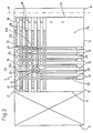
- Figure 2 shows a plan view of the Figure 1 machine.
- Number 1 in Figure 1 indicates a cutting machine comprising:
- a known
loading station 2; - a
fixed structure 3, the top surface of which defines ahorizontal work surface 3a; - a known cutting station 4; and
- a
device 5 for rotating by 90°, atwork surface 3a, a pack 6 of rectangular panels loaded ontosurface 3a atloading station 2. - With reference to Figure 1,
loading station 2 comprises aplatform 7 supporting astack 8 of panels from which, by means of push means not shown, a pack 6 is removed and loaded ontowork surface 3a.Platform 7 presents means for movingstack 8 up and down. - With reference to Figure 2, when viewed from above,
work surface 3a is rectangular, with twoedges edges edges Edges edges edge 13 constitutes a reference point (known as 0 point) for both loading and cutting. Pack 6, in fact, when being loaded, before and after being rotated 90°, when being transferred to cutting station 4, and when being cut, always presents one (long or short) side in line withedge 13. - Close to
loading station 2,work surface 3a presents a number of throughslots 15 with longitudinal axes parallel to one another and to cutting line A, and defined betweenedge 14 and the central portion ofsurface 3a. Fromslots 15 toedge 13,work surface 3a presents acheckerboard portion 16 with a number of gaps in line with and continuing fromslots 15 up toedge 13. Said gaps present the same width asslots 15, with the exception of one, indicated 16a, which presents a width equal to the total width of twoadjacent slots 15 and the solid portion defined between them. - Close to
edge 13,work surface 3a presents a number of throughslots 17 originating fromedge 11, having longitudinal axes parallel to one another and perpendicular to cutting line A, and defined betweenedge 11 andportion 16. Finally, close toedge 13,work surface 3a presents a number of throughslots 18 originating fromedge 12, in line with and of the same width and number asslots 17, and defined betweenedge 12 andportion 16. -
Portion 16 presents a number of gaps in line with and continuing fromslots slots adjacent slots 17 and the solid portion defined between them. The axes ofgaps 16a, 16b intersect perpendicularly; and the total length ofslots 15 and the respective in-line gaps inportion 16 is less than the total length ofslots portion 16. The solid portions ofwork surface 3a are fitted with known rollers (not shown), the longitudinal axes of which are parallel to cutting line A. - With reference to Figures 1 and 2,
device 5 comprises acolumn 21 rotating about a vertical axis B at which the axes ofgaps 16a, 16b intersect, and which is eccentric in relation to a vertical axis through the geometric center ofwork surface 3a.Device 5 also comprises aframe 22 supported bycolumn 21; means 23 for rotatingcolumn 21 and henceframe 22 about axis B; and means 24 for movingcolumn 21 and henceframe 22 up and down alongaxis B. Means structure 3.Frame 22 is horizontal, and comprises amember 25 fitted tocolumn 21; and a number ofmembers 26 fitted to and abovemember 25, having respective longitudinal axes parallel to one another and perpendicular to the longitudinal axis ofmember 25, and the length of which is just short of the total length ofslots 15 and the respective in-line gaps inportion 16. - With reference to Figure 1, in the non-limiting embodiment shown, means 23 comprise an
electric motor 27, the output shaft of which is fitted with agear 28 meshing with agear 31 formed oncolumn 21; and, again in the non-limiting embodiment shown, means 24 comprise ahydraulic actuator 32 beneath and coaxial withcolumn 21, and supplied by a hydraulic system 33 (shown schematically) for movingcolumn 21 along axis B. A thrust bearing 34 between the bottom portion ofcolumn 21 and the rod ofactuator 32 permits rotation ofcolumn 21; and abracket 35, connected in axially-fixed and angularly-free manner tocolumn 21, supportsmotor 27 to enable it to accompany the linear movement ofcolumn 21. Loadingstation 2, cutting station 4 and device 5 (in particular, means 23 and 24) are controlled by anelectronic control system 36. - With reference to Figure 2, in actual use, when loading pack 6 onto
work surface 3a, frame 22 (as illustrated by the continuous line) is positioned beneathwork surface 3a, withmembers 26 parallel to cutting line A and just beneathslots 15 and the respective in-line gaps inportion 16, and withmember 25 just beneathgap 16b inportion 16. Pack 6 is pushed ontowork surface 3a until the longer side of the pack corresponds withmember 26 closest to cutting line A, during which loading stage, the shorter side of pack 6 is aligned withedge 13 constituting the 0 reference point for the cutting stage. - At this point, means 24
move frame 22 upwards parallel to itself and beyondwork surface 3a, so as to detach pack 6 fromsurface 3a; and means 23rotate column 21, and henceframe 22, 90° anticlockwise (in Figure 2) so thatframe 22 is now positioned (as shown by the dotted line in Figure 2 and the continuous line in Figure 1) withmembers 26 parallel toedge 13 and just overslots portion 16; withmember 25 just over gap 16a inportion 16; and with the longer side of pack 6, which in the first position offrame 22 corresponded withmember 26 closest to cutting line A, now in line withedge 13. This is made possible by the distance between rotation axis B andedge 13 being made equal to the distance between rotation axis B and the outermost side ofmember 26 closest to cutting line A in the first position offrame 22. - As pack 6 is raised, and more specifically on
frame 22 first coming into contact with the pack, a number of known grippingmeans 37, fitted to theaforementioned member 26, grip pack 6 to prevent misalignment of the individual panels as it is raised. - Following rotation of
frame 22 and hence pack 6 bymeans 23, means 24move frame 22 down, beneath workingsurface 3a, throughslots portion 16, during which downward movement, gripping means 37 release pack 6 which is deposited ontosurface 3a. The push means at loadingstation 2, or further push means, feed pack 6 towards cutting station 4; and, after pack 6 is cut, the above operation offrame 22 is repeated in reverse, in preparation for the next operating cycle, should machine 1 require 90° rotation of pack 6. - The advantages of the present invention are as follows.
- In particular, it provides for a machine enabling 90° rotation of the pack with no chafing and hence no surface scratching of the panels. Moreover, during the loading stage, during transfer to the cutting station, and during the cutting stage, one side of the pack on the work surface is always aligned with the 0 reference point regardless of the angular position of the pack in relation to the rotation axis of the supporting frame, thus reducing the travel of the cutting blade on the machine. The lateral position of the pack in relation to the work surface also provides for reducing the travel of the follow-up tools and members after the first cut. As such, the present invention provides for reducing the operating time of the machine, and so reducing overall production cost. Finally, a further point to note is the straightforward design of the device by which the pack is rotated.
- Clearly, changes may be made to machine 1 as described and illustrated herein within the scope of the claims.
Claims (10)
- A cutting machine comprising:a loading station (2) for loading a pack (6) of rectangular panels;a cutting station (4);a fixed structure (3) between said loading station (2) and said cutting station (4), including a horizontal work surface (3a) with a first lateral edge (13) perpendicular to a cutting line (A) defined in said cutting station (4);a device (5) for rotating by 90°, at said work surface (3a), said pack (6) of panels loaded onto said work surface (3a) at said loading station (2);said device (5) comprising a horizontal frame (22) for supporting said pack (6); first means (24) for moving said frame (22) from a level below to a level above said work surface (3a) and vice versa; and second means (23) for rotating said frame (22) 90° clockwise and vice versa about an unmoving rotation axis (B) perpendicular to the work surface (3a) when said frame (22) is above said work surface (3a);
said work surface (3a) defining a first opening (15 and 16) with a longitudinal axis parallel to said cutting line (A), for enabling said frame (22) to move freely from a level below to a level above said work surface (3a) and vice versa; and a second opening (17, 18 and 16) with a longitudinal axis perpendicular to said cutting line (A), for enabling said frame (22) to move freely from a level below to a level above said work surface (3a) and vice versa;
characterized in that said loading station (2) includes means for loading said pack (6) with a first side of said pack (6) aligned with said first lateral edge (13), and with a second side of said pack aligned with the side of said frame (22) parallel to and closest to said cutting line (A); and
in that the distance between said rotation axis (B) and said first lateral edge (13) equals the distance between said rotation axis (B) and said side of said frame (22) parallel to and closest to said cutting line (A) when said frame (22) is aligned with said first opening. - A machine as claimed in Claim 1, characterized in that said work surface (3a) includs a plurality of first through slots (15) with longitudinal axes parallel to one another and to said cutting line (A); and a checkerboard portion (16) defined by said first slots (15) and a plurality of first gaps in line with and continuing from said first slots (15); and said first slots (15) being defined from a second edge (14) of said work surface (3a) to said checkerboard portion (16).
- A machine as claimed in Claim 2, characterized in that said first gaps in said checkerboard portion (16) define the same width as said first slots (15), with the exception of one (16a) of said first gaps, which defines a width equal to the total width of two adjacent first slots (15) and the solid portion defined between said adjacent first slots (15).
- A machine as claimed in Claim 2, characterized in that said work surface (3a) defines : a plurality of second through slots (17) parallel to said first edge and originating from a third edge (11) of said work surface (3a) close to said loading station (2); a plurality of second gaps in said checkerboard portion (16), in line with and continuing from said second slots (17); and a plurality of third through slots (18) in line with and continuing from said second gaps, and defined up to a fourth lateral edge (12) of said work surface (3a) close to said cutting line (A).
- A machine as claimed in Claim 4, characterized in that said checkerboard portion (16) are of the same width as said second and third slots (17 and 18), with the exception of one (16b) of said second gaps, which is of a width equal to the total width of two adjacent said second slots (17) and the solid portion defined between said adjacent second slots (17).
- A machine as claimed in Claim 5, characterized in that said wider first gap (16a) and said wider second gap (16b) define longitudinal axes intersecting perpendicularly at said rotation axis (B).
- A machine as claimed in Claim 1, characterized in that said device (5) further comprises a column (21) coaxial with said rotation axis (B), and which is moved axially by said first means (24) and rotated about said rotation axis (B) by said second means (23); said column (21) supporting said frame (22).
- A machine as claimed in Claim 7, characterized in that said frame (22) comprises a first member (25) fitted to said column (21); and a plurality of second members (26) fitted to said first member (25) and having respective longitudinal axes parallel to one another and perpendicular to the longitudinal axis of said first member (25); when said frame (22) is aligned with said first opening, said second members (26) aligned with said first slots (15) and said first gaps in said portion (16), and said first member (25) aligned with said wider second gap (16b); and, when said frame (22) is aligned with said second opening, said second members (26) correspond with said second and third slots (17 and 18) and said second gaps in said checkerboard portion (16), and said first member (25) corresponds with said wider first gap (16a).
- A machine as claimed in any one of the foregoing Claims, characterized in that said frame (22) presents means (37) for clamping said pack (6) to said frame (22), particularly during 90° rotation of the same.
- Use of a machine as claimed in any of claims 1-9, wherein the following stages are carried out:- a first loading stage wherein said pack (6) of panels is loaded onto said work surface (3a) until a first side of said pack (6) is aligned with an edge (13) of work surface (3a) constituting the 0 reference point and until a second side of said pack (6) is aligned with member (26), belonging to the frame (22), closest to cutting line (A);- a second raising stage of said frame (22) parallel to itself so as to detach said pack (6) from said work surface (3a);- a third rotating stage of frame (22) bearing said pack (6) until said second side of said pack (6), which at first loading stage corresponded with said member (26) closest to cutting line (A), is in line with edge (13); and- a fourth cutting stage along a line (A) perpendicular to said edge (13).
Applications Claiming Priority (2)
| Application Number | Priority Date | Filing Date | Title |
|---|---|---|---|
| ITBO930214 | 1993-05-17 | ||
| IT93BO000214A IT1266352B1 (en) | 1993-05-17 | 1993-05-17 | PANEL SECTIONING MACHINE. |
Publications (2)
| Publication Number | Publication Date |
|---|---|
| EP0625405A1 EP0625405A1 (en) | 1994-11-23 |
| EP0625405B1 true EP0625405B1 (en) | 1997-12-10 |
Family
ID=11339034
Family Applications (1)
| Application Number | Title | Priority Date | Filing Date |
|---|---|---|---|
| EP94107600A Expired - Lifetime EP0625405B1 (en) | 1993-05-17 | 1994-05-16 | Panel cutting machine |
Country Status (6)
| Country | Link |
|---|---|
| US (1) | US5850774A (en) |
| EP (1) | EP0625405B1 (en) |
| AT (1) | ATE160961T1 (en) |
| DE (1) | DE69407213T2 (en) |
| ES (1) | ES2110650T3 (en) |
| IT (1) | IT1266352B1 (en) |
Families Citing this family (18)
| Publication number | Priority date | Publication date | Assignee | Title |
|---|---|---|---|---|
| US6435066B1 (en) | 1997-12-18 | 2002-08-20 | Springs Window Fashions Division, Inc. | Cutting apparatus for window covering and methods therefor |
| US6193458B1 (en) * | 1999-04-29 | 2001-02-27 | Jeffrey D. Marsh | System for and method of binding and trimming a perfect bound book |
| US7014182B2 (en) * | 1999-04-29 | 2006-03-21 | Marsh Jeffrey D | Apparatus and method of on demand printing, binding, and trimming a perfect bound book |
| US7017459B2 (en) * | 1999-07-23 | 2006-03-28 | Shade-O-Matic Limited | Blind cut down machine |
| US7918150B2 (en) | 1999-07-23 | 2011-04-05 | Shade-O-Matic Limited | Blind cut down machine |
| IT1320963B1 (en) * | 2000-03-30 | 2003-12-18 | Giben Impianti Spa | PROCEDURE AND DEVICE FOR MAKING A SERIES OF CUTS WITH DIFFERENT ORIENTATIONS ON ONE OR MORE PANELS BY MEANS OF ONE |
| DE10045062A1 (en) * | 2000-09-12 | 2002-03-21 | Gaemmerler Ag | stacker |
| AU2001296278A1 (en) | 2000-09-21 | 2002-04-02 | Jeffrey D. Marsh | Book trimming apparatus and method |
| GB2426757B (en) * | 2005-06-03 | 2008-02-27 | Crt Heaven Ltd | Apparatus and method for cutting a cathode ray tube |
| US20070017780A1 (en) * | 2005-07-20 | 2007-01-25 | Mekanika Inc. | Transfer and distribution conveyor system |
| ITBO20050552A1 (en) * | 2005-09-09 | 2007-03-10 | Giben Int Spa | CUTTING MACHINE |
| US7963733B2 (en) | 2008-10-01 | 2011-06-21 | Perfect Systems, Llc | Apparatus for and a method of binding of a perfect bound book |
| US20110044786A1 (en) * | 2009-08-18 | 2011-02-24 | Perfect Systems, Llc | Apparatus for and method of clamping and trimming a perfect bound book |
| US8739730B2 (en) * | 2009-12-17 | 2014-06-03 | Jeffrey D. Marsh | Apparatus for and a method of determining condition of hot melt adhesive for binding of a perfect bound book |
| GB2492347A (en) * | 2011-06-28 | 2013-01-02 | Nicholas Timothy Showan | Building method, cutting apparatus and liquid-laden foam insulator |
| CN103112075B (en) * | 2012-12-13 | 2016-04-06 | 赵瑞合 | A kind of sheet material and produce the closed assembly pedestal of sheet material, selectable and trimmer |
| ITUA20164532A1 (en) * | 2016-06-20 | 2017-12-20 | Giben Tech S R L | PANEL ROTATION DEVICE |
| AT521555A1 (en) | 2018-07-26 | 2020-02-15 | Fill Gmbh | Panel |
Family Cites Families (16)
| Publication number | Priority date | Publication date | Assignee | Title |
|---|---|---|---|---|
| US569200A (en) * | 1896-10-13 | Machine for scoring cardboard | ||
| US560064A (en) * | 1896-05-12 | Machine for trimming and slitting packs of metal sheets | ||
| GB1149877A (en) * | 1966-11-26 | 1969-04-23 | Enrico Putin | A machine for rotating and cutting lenghts of clay for the production of bricks |
| US3570344A (en) * | 1968-06-18 | 1971-03-16 | Harris Intertype Corp | Apparatus and method for trimming books |
| CA945891A (en) * | 1969-03-24 | 1974-04-23 | Yukio Yabuta | Method for cutting a metal web utilizing an electro-magnetic induction type feeding apparatus |
| US3818790A (en) * | 1972-11-29 | 1974-06-25 | Armstrong Cork Co | Carpet tile cutter |
| US3908980A (en) * | 1973-08-02 | 1975-09-30 | Alexander Fowler | Work loading, unloading, and positioning means for handling sheet material in power presses and the like |
| DE3021826A1 (en) * | 1980-06-11 | 1981-12-17 | Schloemann-Siemag AG, 4000 Düsseldorf | ALIGNMENT AND MEASURING DEVICE FOR ROLLER SHEETS |
| DE3118379A1 (en) * | 1981-05-09 | 1982-11-25 | Dimter GmbH Maschinenfabrik, 7918 Illertissen | Apparatus for feeding wooden boards |
| DE3128917A1 (en) * | 1981-07-22 | 1983-03-10 | Weykam, Gottfried Johannes, Dr., 4700 Hamm | "TURNING DEVICE FOR PIECES, IN PARTICULAR FOR BAGS" |
| DE8706809U1 (en) * | 1987-05-12 | 1987-07-16 | H & K Verpackungstechnik GmbH, 4600 Dortmund | Device for turning piece goods |
| US5002108A (en) * | 1988-09-28 | 1991-03-26 | Erwin Jenkner | Process for the edge planning of rectangular plates |
| DE3907566C1 (en) * | 1989-03-09 | 1990-08-30 | Buettner, Hans Hugo, 4020 Mettmann, De | Device for turning packages moved on a conveyor stretch |
| US5176056A (en) * | 1989-10-26 | 1993-01-05 | Selco S.R.L. | Panel cutting machine |
| DE3939596A1 (en) * | 1989-11-30 | 1991-06-06 | Wolfgang Mohr | DEVICE FOR CUTTING STACKED, SHEET-SHAPED GOODS |
| GB2281048B (en) * | 1992-05-05 | 1995-10-25 | Marquip Inc | Apparatus and method for slitting corrugated paperboard boxes |
-
1993
- 1993-05-17 IT IT93BO000214A patent/IT1266352B1/en active IP Right Grant
-
1994
- 1994-05-16 DE DE69407213T patent/DE69407213T2/en not_active Expired - Lifetime
- 1994-05-16 EP EP94107600A patent/EP0625405B1/en not_active Expired - Lifetime
- 1994-05-16 ES ES94107600T patent/ES2110650T3/en not_active Expired - Lifetime
- 1994-05-16 AT AT94107600T patent/ATE160961T1/en not_active IP Right Cessation
-
1996
- 1996-06-26 US US08/668,319 patent/US5850774A/en not_active Expired - Fee Related
Also Published As
| Publication number | Publication date |
|---|---|
| ITBO930214A1 (en) | 1994-11-17 |
| ITBO930214A0 (en) | 1993-05-17 |
| ATE160961T1 (en) | 1997-12-15 |
| US5850774A (en) | 1998-12-22 |
| DE69407213D1 (en) | 1998-01-22 |
| EP0625405A1 (en) | 1994-11-23 |
| ES2110650T3 (en) | 1998-02-16 |
| IT1266352B1 (en) | 1996-12-27 |
| DE69407213T2 (en) | 1998-04-02 |
Similar Documents
| Publication | Publication Date | Title |
|---|---|---|
| US5850774A (en) | Panel cutting machine | |
| US10873000B2 (en) | Method and automatic production plant for printing on photovoltaic cells | |
| US4037730A (en) | Press line with workpiece feeding device | |
| CN102114604B (en) | A kind of automatic loading and unloading device of sheet processing equipment | |
| US6152678A (en) | Apparatus for the mechanical handling of pallets | |
| EP4134334B1 (en) | Automatic distribution wall | |
| EP0205064A2 (en) | A plant for automatically stacking and orderly arranging packs of panels of different sizes | |
| CN110340671A (en) | Integrated plate automatic cutting and welding equipment | |
| EP1689540A1 (en) | Conveyor for transporting work pieces in a press | |
| CN213797882U (en) | Optical lens cutting and stacking machine | |
| KR101145138B1 (en) | Slab shift apparatus | |
| US3907125A (en) | Apparatus for the delivery and removal of palettes provided with work-pieces on machine tools | |
| US5680787A (en) | Indexing conveyor for a die transfer system | |
| EP1677953B1 (en) | A panel turning device | |
| CN217837584U (en) | Trimming machine capable of continuously stacking plates | |
| EP0691291B1 (en) | Automatic handling device, particularly for slabs of marble, granite, and other stone materials | |
| CN217200146U (en) | Roller platform is carried between two parties | |
| US4901840A (en) | Apparatus for transferring work-supporting pallets | |
| CN111039004B (en) | Sorting, conveying and unstacking mechanism | |
| CN117020045B (en) | Punch device with multi-axis cooperative motion, synchronous feeding method and control system | |
| CN209453227U (en) | The charging and discharging mechanism of cut edge equipment | |
| US5454149A (en) | Palette changer for machine tools | |
| CN218560040U (en) | Rock wool material loading machine with length cuts and automatic function of filling | |
| CN118456134A (en) | Automatic edging equipment | |
| CN112975621A (en) | Flat grinding device |
Legal Events
| Date | Code | Title | Description |
|---|---|---|---|
| PUAI | Public reference made under article 153(3) epc to a published international application that has entered the european phase |
Free format text: ORIGINAL CODE: 0009012 |
|
| AK | Designated contracting states |
Kind code of ref document: A1 Designated state(s): AT DE ES FR GB IT |
|
| 17P | Request for examination filed |
Effective date: 19950316 |
|
| 17Q | First examination report despatched |
Effective date: 19961002 |
|
| GRAG | Despatch of communication of intention to grant |
Free format text: ORIGINAL CODE: EPIDOS AGRA |
|
| GRAG | Despatch of communication of intention to grant |
Free format text: ORIGINAL CODE: EPIDOS AGRA |
|
| GRAH | Despatch of communication of intention to grant a patent |
Free format text: ORIGINAL CODE: EPIDOS IGRA |
|
| RAP1 | Party data changed (applicant data changed or rights of an application transferred) |
Owner name: SELCO S.P.A. |
|
| GRAH | Despatch of communication of intention to grant a patent |
Free format text: ORIGINAL CODE: EPIDOS IGRA |
|
| GRAA | (expected) grant |
Free format text: ORIGINAL CODE: 0009210 |
|
| AK | Designated contracting states |
Kind code of ref document: B1 Designated state(s): AT DE ES FR GB IT |
|
| REF | Corresponds to: |
Ref document number: 160961 Country of ref document: AT Date of ref document: 19971215 Kind code of ref document: T |
|
| REF | Corresponds to: |
Ref document number: 69407213 Country of ref document: DE Date of ref document: 19980122 |
|
| ITF | It: translation for a ep patent filed | ||
| REG | Reference to a national code |
Ref country code: ES Ref legal event code: FG2A Ref document number: 2110650 Country of ref document: ES Kind code of ref document: T3 |
|
| ET | Fr: translation filed | ||
| PLBE | No opposition filed within time limit |
Free format text: ORIGINAL CODE: 0009261 |
|
| STAA | Information on the status of an ep patent application or granted ep patent |
Free format text: STATUS: NO OPPOSITION FILED WITHIN TIME LIMIT |
|
| 26N | No opposition filed | ||
| PGFP | Annual fee paid to national office [announced via postgrant information from national office to epo] |
Ref country code: AT Payment date: 20010515 Year of fee payment: 8 |
|
| PGFP | Annual fee paid to national office [announced via postgrant information from national office to epo] |
Ref country code: GB Payment date: 20010516 Year of fee payment: 8 |
|
| PGFP | Annual fee paid to national office [announced via postgrant information from national office to epo] |
Ref country code: FR Payment date: 20010528 Year of fee payment: 8 |
|
| REG | Reference to a national code |
Ref country code: GB Ref legal event code: IF02 |
|
| PG25 | Lapsed in a contracting state [announced via postgrant information from national office to epo] |
Ref country code: GB Free format text: LAPSE BECAUSE OF NON-PAYMENT OF DUE FEES Effective date: 20020516 Ref country code: AT Free format text: LAPSE BECAUSE OF NON-PAYMENT OF DUE FEES Effective date: 20020516 |
|
| GBPC | Gb: european patent ceased through non-payment of renewal fee |
Effective date: 20020516 |
|
| PG25 | Lapsed in a contracting state [announced via postgrant information from national office to epo] |
Ref country code: FR Free format text: LAPSE BECAUSE OF NON-PAYMENT OF DUE FEES Effective date: 20030131 |
|
| REG | Reference to a national code |
Ref country code: FR Ref legal event code: ST |
|
| PGFP | Annual fee paid to national office [announced via postgrant information from national office to epo] |
Ref country code: ES Payment date: 20070524 Year of fee payment: 14 |
|
| REG | Reference to a national code |
Ref country code: ES Ref legal event code: FD2A Effective date: 20080517 |
|
| PG25 | Lapsed in a contracting state [announced via postgrant information from national office to epo] |
Ref country code: ES Free format text: LAPSE BECAUSE OF NON-PAYMENT OF DUE FEES Effective date: 20080517 |
|
| PGFP | Annual fee paid to national office [announced via postgrant information from national office to epo] |
Ref country code: DE Payment date: 20110511 Year of fee payment: 18 |
|
| PGFP | Annual fee paid to national office [announced via postgrant information from national office to epo] |
Ref country code: IT Payment date: 20120523 Year of fee payment: 19 |
|
| REG | Reference to a national code |
Ref country code: DE Ref legal event code: R119 Ref document number: 69407213 Country of ref document: DE Effective date: 20121201 |
|
| PG25 | Lapsed in a contracting state [announced via postgrant information from national office to epo] |
Ref country code: DE Free format text: LAPSE BECAUSE OF NON-PAYMENT OF DUE FEES Effective date: 20121201 |
|
| PG25 | Lapsed in a contracting state [announced via postgrant information from national office to epo] |
Ref country code: IT Free format text: LAPSE BECAUSE OF NON-PAYMENT OF DUE FEES Effective date: 20130516 |