EP0624526A2 - Closure for container with liquid or pasty contents - Google Patents
Closure for container with liquid or pasty contents Download PDFInfo
- Publication number
- EP0624526A2 EP0624526A2 EP94107271A EP94107271A EP0624526A2 EP 0624526 A2 EP0624526 A2 EP 0624526A2 EP 94107271 A EP94107271 A EP 94107271A EP 94107271 A EP94107271 A EP 94107271A EP 0624526 A2 EP0624526 A2 EP 0624526A2
- Authority
- EP
- European Patent Office
- Prior art keywords
- closure
- container
- spring
- nozzle
- flaps
- Prior art date
- Legal status (The legal status is an assumption and is not a legal conclusion. Google has not performed a legal analysis and makes no representation as to the accuracy of the status listed.)
- Granted
Links
Images


Classifications
-
- B—PERFORMING OPERATIONS; TRANSPORTING
- B65—CONVEYING; PACKING; STORING; HANDLING THIN OR FILAMENTARY MATERIAL
- B65D—CONTAINERS FOR STORAGE OR TRANSPORT OF ARTICLES OR MATERIALS, e.g. BAGS, BARRELS, BOTTLES, BOXES, CANS, CARTONS, CRATES, DRUMS, JARS, TANKS, HOPPERS, FORWARDING CONTAINERS; ACCESSORIES, CLOSURES, OR FITTINGS THEREFOR; PACKAGING ELEMENTS; PACKAGES
- B65D47/00—Closures with filling and discharging, or with discharging, devices
- B65D47/04—Closures with discharging devices other than pumps
- B65D47/20—Closures with discharging devices other than pumps comprising hand-operated members for controlling discharge
- B65D47/2018—Closures with discharging devices other than pumps comprising hand-operated members for controlling discharge comprising a valve or like element which is opened or closed by deformation of the container or closure
- B65D47/2025—Flexible bung-type elements
-
- B—PERFORMING OPERATIONS; TRANSPORTING
- B65—CONVEYING; PACKING; STORING; HANDLING THIN OR FILAMENTARY MATERIAL
- B65D—CONTAINERS FOR STORAGE OR TRANSPORT OF ARTICLES OR MATERIALS, e.g. BAGS, BARRELS, BOTTLES, BOXES, CANS, CARTONS, CRATES, DRUMS, JARS, TANKS, HOPPERS, FORWARDING CONTAINERS; ACCESSORIES, CLOSURES, OR FITTINGS THEREFOR; PACKAGING ELEMENTS; PACKAGES
- B65D47/00—Closures with filling and discharging, or with discharging, devices
- B65D47/04—Closures with discharging devices other than pumps
- B65D47/20—Closures with discharging devices other than pumps comprising hand-operated members for controlling discharge
- B65D47/2018—Closures with discharging devices other than pumps comprising hand-operated members for controlling discharge comprising a valve or like element which is opened or closed by deformation of the container or closure
- B65D47/2056—Closures with discharging devices other than pumps comprising hand-operated members for controlling discharge comprising a valve or like element which is opened or closed by deformation of the container or closure lift valve type
- B65D47/2081—Closures with discharging devices other than pumps comprising hand-operated members for controlling discharge comprising a valve or like element which is opened or closed by deformation of the container or closure lift valve type in which the deformation raises or lowers the valve port
- B65D47/2087—Closures with discharging devices other than pumps comprising hand-operated members for controlling discharge comprising a valve or like element which is opened or closed by deformation of the container or closure lift valve type in which the deformation raises or lowers the valve port the port being formed by a slidable rigid cap-like element which is moved linearly by the pressure of the contents
Definitions
- the present invention relates to a closure for containers with liquid or pasty content according to the preambles of claims 1, 5 and 8.
- a closure according to the preamble of claim 1 is known for example from EP-A-O 392 208.
- a valve body or cover is also arranged in the closure, which is generally circularly limited, which is guided in a movable manner and lifts off its seat when the contents of the container are pressed.
- the valve cover or body is flowed around on all sides by the container contents, so that essentially a hose forms when the container contents emerge from the opened closure. Since the interior of the hose, with its diameter corresponding to the diameter of the valve body, must be filled with air, the hose tears open directly at the trailing edge, so that air can enter the interior of the container there.
- a closure according to the preamble of claim 8 is known from US-A 2 028 843 and from EP-A 0 392 208 already mentioned.
- the closure is provided with a single lid or a flap which is under spring action and is thus kept closed.
- the content pressed out of the container against the force of this locking spring leaves the container in a compact strand.
- it can be deflected laterally under the action of the spring-loaded flap, which may be undesirable. If it is a liquid in the container contents, there may be the possibility that this is widely distributed or even divided under the flap or lid effect, which is undesirable in certain cases.
- the present invention is therefore based on the object of designing a closure in such a way that its functionality is fully preserved over the entire period of use, that the contents of the container in a compact strand or jet can be metered very finely depending on the pressure exerted on the container and that the closure is inexpensive to manufacture.
- the construction of the closure which is basically very simple, has the advantage, first of all, that it can be manufactured very inexpensively, since the cover part can also be formed as an injection molded part, like the supporting body to which the cover part is advantageously molded .
- the cover part encloses at least one wing of the supporting body which is movable about a pivot axis, this wing giving the cover part the necessary stability to ensure a reproducible open and / or.
- the wing is advantageously connected to the pivot axis of the carrier body by means of a film hinge, since the material of the carrier body has a low elasticity according to the invention, so that a perfect pivoting movement is possible.
- at least one pull rib extending approximately in the closing direction is formed on the cover part, which pulls the pivoted cover part into a closed position due to its elastic forces, in which it lies sealingly.
- the material with high elasticity from which the cover part is made Santoprene (registered trademark) or another suitable thermoplastic material, this material having an excellent sealing effect in the event that it is in the sense of a sealing lip is pressed against an opening edge.
- the low elasticity material from which the support body is made is preferably made of polyurethane or polypropylene. These plastics have the inherent rigidity necessary for the function of the supporting body.
- the container contents before it reaches the opening of the nozzle, is guided around the filler piece within the nozzle, so that no possibility there is that the container content is tubular. After passing the filler piece, no air can enter the space downstream of the filler piece, since the container contents are completely enclosed by the nozzle. On the contrary, the nozzle again directs the contents of the container flowing around the filler together to a smaller flow cross section, so that it results in a compact and uniformly shaped strand before it emerges from the nozzle opening.
- This strand of material discharged from the nozzle opening is therefore clear, very good and easy to dose and can also be placed exactly when it is desired that it occupies a certain predetermined space.
- the displaceable nozzle is designed as a tube section, with a recess or narrowing of the diameter arranged at the outer end, into which the preferably conical outer end of the fixed filling piece fits in a sealing manner.
- This design substantially improves the flow around the filler piece when it is squeezed out, the material content is forced downstream into a narrower flow cross section downstream of the filler piece guided so that a compact closed strand of material is fed to the nozzle outlet and exits from it.
- a beam-shaped support is arranged below the common closing joint of the two flaps, the side of this support directed towards the inside of the container being advantageously designed in a cutting shape.
- This support ensures good retention of the opposite flaps in the closed state and thus also a good closure of the container contents.
- this bar-shaped support is only relatively narrow, although it causes a division of the expressed strand at the point at which it is arranged, this division of the expressed strand is immediately reversed again due to the inclined position of the two opposite flaps, which the expressed Compress the strand above this beam-shaped support again, so that a uniform, compact strand emerges between the two opened limits of the flaps.
- the cutting-like design of the beam-shaped support directed towards the inside of the container acts aerodynamically on the strand during the squeezing process, so that there is an even distribution of the strand on both sides and thus neither of the two oppositely arranged flaps is opened further during the squeezing process, so that a deviation of the strand from a straight squeezing direction would result.
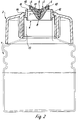
- a bottle 1 made of an elastic material and shown in FIGS. 1 to 4 is closed in the region of its bottle neck with a closure 2 which can be screwed onto the bottle neck 13 by means of a molded screw part 3.
- the closure 2 which, like the bottle 1 in the present exemplary embodiments, is designed as a cylindrical body, is provided in its area partially covering the bottle neck 13 with a cover part 5 which is firmly connected to a support body 4.
- the support body 4 consists of a support body jacket 12, which is supported on the bottle neck 13 with a circumferential attachment 14. In its upper end region facing away from the bottle neck 13, the supporting body jacket is formed on the inside as a sealing surface 15, while, as FIG. 4 shows very clearly, one in the middle region Pivot axis 7 extends from one side of the inner wall of the support body shell 12 to the other side.
- wings 6 are connected on both sides to this pivot axis 7, the connection between the wings 6 and the pivot axis being effected via a film hinge 8, so that a smooth pivoting movement of the wings 6 is possible.
- the entire support body 4, that is, both the support body jacket 12 and the pivot axis 7 and the wings 6 are made of a material, preferably a plastic, with low elasticity.
- the pivot axis 7 and the wings 6 are encased by the cover part 5, which consists of a material of high elasticity.
- the cover part 5 which consists of a material of high elasticity.
- an intimate bond between the wings 6 and the cover part 5 is achieved in that openings 11 in the wings 6 are filled with the material of the cover part 5, so that there is practically a positive connection.
- the outer edge of the cover part 5, which faces the supporting body jacket 12, is designed as a sealing lip 10 which, in the closed position, lies sealingly against the sealing surface 15 of the supporting body jacket 12.
- the lid part 5 is provided in the area of each wing 6 with a pull rib 17 which, due to its elastic forces, pulls the sealing area of the lid part 5 into a closed position for closing.
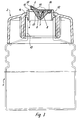
- FIGS. 1 and 2 represents a support body 4 which has two wings 6, so that the cover part 3 is an embodiment variant in which the cover part can only be opened on one side, with only one pivotable wing being provided for this purpose, while the other side is one with the supporting body jacket 12 firmly connected collar 16 is formed.
- the lid part is opened by squeezing the bottle 1, the bottle contents being pressed against the underside of the lid part 5, and the lid part 5 is thus practically weighed out by the applied pressure force. After this squeezing has ended, ie when there is no longer any pressing pressure on the cover part 5, it is returned to a closed position by the material-related elastic forces. In the closed position, the sealing lip 10 nestles against the sealing surface 1 so that the inside of the bottle is largely protected.
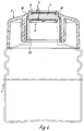
- FIGS. 6 to 11 also designed as a bottle container 21 for liquid or pasty content is provided with a neck 22, on the outer surface of a screw thread 3 for a cap or the like. is arranged.
- a closure cap 25 with an inner end, which is designed as an outwardly standing annular flange 26, optionally with the interposition of a seal 27, against the upper edge 28 of the container neck 22 captured.
- the cap 25 continues the container neck 22 to a certain extent.
- a holder 29 for a centrally arranged filler piece 30 is formed and fastened.
- This holder 29 consists of an outer ring 31, from which individual spokes protrude inwards, on which the filler piece 30, projecting upwards, is stuck. This whole arrangement can be molded in one piece from plastic.
- the filler 30 is designed as a cylindrical body in its The uppermost region projects beyond a central opening in the closure cap 25 and is expediently designed there as a cone 33 with a diameter constriction.
- a nozzle 34 is slidably guided.
- This nozzle 34 consists of a tube section which is provided at its inner end with an outwardly extending flange 35.
- This flange 35 lies with its outer surface on the inner surface of the cap 25 and serves as a guide for the nozzle 34.
- an inwardly directed flange 36 is formed on the cap 25 at the outer end, which with its inner surface against the outer surface of the tubular part the nozzle 34 abuts and this also leads.
- a compression spring 37 is arranged, which is designed as a helical spring, on the one hand abuts against the flange 36 and on the other hand against the flange 35. This compression spring 37 holds the nozzle 34 in the closed position shown in FIG. 6.
- This nozzle is formed at its outer end as a hollow cone 38 with a central opening 39. Between the inner surface of the hollow cone 38 and the flat outer surface of the cone-shaped formation 33 in the outer end of the filler 30, a solid and tight closure forms in the closed state of the nozzle .
- the free inside diameter of the nozzle 34 is substantially larger than the outside diameter of the filling piece 30, so that a further free space is created within the nozzle 34 which surrounds the filling piece 30.
- the compression spring 37 is designed in terms of its spring characteristics such that it holds the nozzle 34 with a tight seal against the filler 10, but yields when the contents of the container 21 are pressed, so that the nozzle 34 is guided within the opposite of the stuck filler 30
- Closure cap 25 is displaced outwards by means of the flanges 35 and 36 and thus releases the nozzle opening 39, so that the position corresponding to FIG. 7 is reached.
- the contents of the container flow then around the filler 30, within the space between the filler and the nozzle to the opening 39. Due to the conically contracted shape 38 of the nozzle 34, which now lies above the upper conical end 33 of the filler 30, the expressed container content is compressed in this area and formed into a compact strand before it can exit the nozzle opening 39.
- the spring 37 is more or less compressed and thus the distance of the nozzle opening 39 is removed from the outer end 33 of the filler piece 30, so that the passage cross section between the upper nozzle end and the filler piece is increased or decreased and accordingly, a larger or smaller amount of the container contents can pass between the outer end 33 of the filler 30 and the outer end of the nozzle 34, which is designed as a hollow cone 38, to the nozzle opening 39, in order to emerge there as a compact, uniformly shaped strand.
- a closure cover 40 is provided which engages over the upper end of the closure cap 25 and is clipped on or screwed on there.
- the closure cover 30 lies with its inner surface firmly against the outer surface of the nozzle 34 and the filler piece 30, so that the nozzle 34 cannot be lifted off the filler piece 30 and thus open the opening 39.
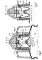
- FIGS. 8 to 10 Another exemplary embodiment is shown in FIGS. 8 to 10, the same reference numerals being used for the same parts.
- the holder ring 31 for the filler 30 is provided with a holder 41 for the bar or leaf spring 42, which is shaped in the form of a W and protrudes into the neck 22 of the container 21.
- the nozzle 34 is provided with lugs 43 which protrude below the filler 30 into the container neck 22 and at its end engage under a crest 45 of the inner angle 46 of the W-shaped spring 42 with a transverse connecting piece 44.
- the outer long legs 47 of the W-shaped spring run approximately parallel in the closed state of the closure to the wall of the container neck 2, as can be seen from FIG. 8.
- the W-shaped spring 22 is slightly tensioned in this state in order to keep the closure closed.
- the W-shaped spring yields and the state corresponding to FIG. 9 is established.
- the nozzle 34 is displaced outward in its guide 35, 36 with respect to the filler 30 and opens the opening 39, the spring 42 being tensioned more by bending its long legs 47 and its inner angle 46.
- the spring 42 pulls the nozzle 34 back against the filler until the opening 39 is closed. All other functions correspond to the description given above in connection with the exemplary embodiment according to FIGS. 6 and 7.
- FIG. 11 shows a greatly enlarged partial section of FIG. 6 or 8.
- a sealing lip 49 is formed on the outside of the flange. This prevents the contents of the container from getting into the nozzle guide and thus impairing the nozzle movement.
- the closure according to the invention is designed in particular with regard to the arrangement of the spring such that it forms a coherent unit. On the one hand, it is therefore easy to manufacture, on the other hand, in a considerably advantageous manner compared to the previously known closures, it is easy to assemble or can be retrofitted or exchanged on any container with a standardized screw neck without any changes or special interventions on the container.
- a lid 53 is placed on the neck 51 of the container 52, which is seated on the upper edge of the neck 51 with an annular flange 54 projecting outwards, possibly with an intermediate layer in the form of a seal .
- the cover 53 is held in place by a cap 55, which has a screw thread 56 is screwed onto the thread arranged on the outside of the neck 51, the cap 55 being provided with an inwardly projecting circular projection 57 which overlaps the flange 54.
- This entire arrangement can be used instead of a conventional screw cap closing the container and can be exchanged for this screw cover, so that each container with a standard screw cover can be provided with this closure.
- the central region of the cover 53 is provided with an opening 58, for example rectangularly limited, on the outer edges of which flaps 59 are hinged 60.
- the flaps 59 are opposite, so that when they are opened they open an opening slot between their mutually opposing edges 61 through which the contents of the container can escape.
- the opening 58 is provided in its center with a beam-shaped support 62, on which the mutually opposing outer edges 61 of the flaps 59 rest in a sealed manner in the closed state.
- these outer edges 61 can be designed such that they cover the beam-shaped support 62 in the closed state on the upper side and on the two side surfaces with an angular profile 63.
- the overall arrangement is preferably designed in such a way that all of the above-described individual parts consist of plastic and are injection molded together in a mold, the hinges 60 being designed as film hinges.
- Arms protruding into the container neck 51 are integrally formed near the two side edges of the flaps 59, and are expediently in one piece and made of the same material as the flaps 59, this material being flexible or resilient due to the cross-sectional configuration of the arms 64.
- the arms 64 are provided with widenings 65, the lower and the two sides of the flaps 59 project downwards and lie against the sides of the openings 58 in the lid 53, so that when the flaps 59 swing open, the container contents cannot emerge towards the sides, but are directed towards the center exclusively through the slot formed between the two flaps 59.
- the arms 64 of the flaps 59 are connected to one another by a crossbar 66.
- a leaf spring 67 is arranged below the cover 53.
- the free ends 68 of the leaf spring 67 are anchored in an annular part 69, which surrounds the inside of the cover 53 between the flanges 54 on the cover and the boundary of the opening 58 in the cover 53.
- the leaf spring 67 is shaped like a large W with long upstanding outer legs 70 and an inner short angle 71, which is connected at the apex 72 to the two arms 64, in such a way that it overlaps the rod 66 connecting the arms 64.
- the W-shaped spring is in a largely relaxed state.
- the arms 64 are also in their normal state and the flaps 59 of the closure are closed.
- the W-shaped spring 67 has a pretension, so that it acts in particular in its central region with the raised inner angle 72 on the connection 66 between the two arms 64, pulling it downward and thus holding the flaps 59 in the closed position.
- the force of the spring 67 is adjusted in such a way that when the pressure on the container contents is not too great, that is to say when the container is compressed, the pressure on the flaps 59 acting inside the container has an opening effect by overcoming the restoring force of the spring 67.
- the flaps 59 open and the position corresponding to FIG.
- an additional securing device can be used, namely a cap, which is not shown here, which lies flat on the two flaps 59 from the outside and above with a central part and with one after the bottom edge is clipped on to the flap 55 or screwed onto it.
- a sealing cap instead of this additional cap, which is similar to the cap 55 and is exchanged for this, the sealing cap, also not shown here, being continued in one piece between the inwardly projecting projection 57, so that this central one Part rests on the outside of the two flaps 59 when screwing onto the thread 56 in a tightly sealing and sealing manner.
- the closure is designed in particular with regard to the arrangement of the spring such that it forms a coherent unit.
Abstract
Description
Die vorliegenden Erfindungen betreffen einen Verschluß für Behälter mit flüssigem oder pastenförmigem Inhalt gemäß den Oberbegriffen der Ansprüche 1, 5 und 8.The present invention relates to a closure for containers with liquid or pasty content according to the preambles of
Ein Verschluß gemäß dem Oberbegriff des Anspruches 1 ist beispielsweise aus der EP-A-O 392 208 bekannt.A closure according to the preamble of
Mit dem darin gezeigten Verschluß ist es möglich, den Behälter, beispielsweise eine aus einem elastischen Material bestehende Flasche oder Tube, einzig und allein durch Zusammendrücken bzw. ein anschließendes Zurückverformen bei einer Grifflockerung zu öffnen bzw. zu schließen, ohne daß der Verschluß selbst dabei betätigt werden muß.With the closure shown therein, it is possible to open or close the container, for example a bottle or tube made of an elastic material, solely by being compressed or subsequently deformed when the handle is loosened, without the closure itself being actuated must become.
Naturgemäß bietet diese Handhabung gegenüber den bis dahin bekannten Verschlüssen erhebliche Handhabungsvorteile.
Insofern hat sich diese Erfindung durchaus bewährt.Naturally, this handling offers considerable handling advantages over the closures known hitherto.
In this respect, this invention has proven itself.
Allerdings bereitet die Realisierung dieser bekannten Konzeption eine einige Probleme, zumal es sich bei solchen Verschlüssen um Massenartikel handelt, die entsprechend kostengünstig herstellbar sein müssen, um eine marktmäßige Akzeptanz zu finden.
Dieser Anforderung wird der genannte bekannte Verschluß nur ungenügend gerecht.However, the implementation of this known concept poses some problems, especially since such closures are mass-produced items that must be correspondingly inexpensive to manufacture in order to find market acceptance.
The known closure mentioned does not sufficiently meet this requirement.
In diesem Sinn ist auch ein aus den Schriften CH-A-229 106, CH-A-267 023, FR-A 1 427 649 und US-A 3 754 690 bekannter Verschluß zu sehen, der dem Gattungsbegriff des Anspruches 5 entspricht.In this sense, one of the documents CH-A-229 106, CH-A-267 023, FR-A 1 427 649 and US-A 3 754 690 see known closure which corresponds to the preamble of claim 5.
Nach diesem Stand der Technik ist überdies in dem Verschluß, der im allgemeinen kreisrund begrenzt ist, ein Ventilkörper oder -deckel angeordnet, der beweglich geführt ist und sich bei einem Druck auf den Inhalt des Behälters von seinem Sitz abhebt. Hierbei wird der Ventildeckel oder - körper von dem Behälterinhalt allseits umströmt, so daß sich beim Austreten des Behälterinhalts aus dem geöffneten Verschluß im wesentlichen ein Schlauch ausbildet. Da der Innenraum des Schlauches, in seinem Durchmesser dem Durchmesser des Ventilkörpers entsprechend, mit Luft gefüllt sein muß, reißt unmittelbar an der Austrittskante der Schlauch auf, damit dort Luft in das Innere des Behälters eintreten kann. In der Praxis fällt der Schlauch jedoch nach dem Aufreißen zusammen, da der Behälterinhalt über den Umfang der ringförmigen Austrittsöffnung ungleichmäßig abgegeben wird, so daß der aus dem Behälter ausgegebene Materialstrang einen äußerst ungleichmäßigen Massequerschnitt aufweist, sowie auch eine ungleichmäßige Form.
Dadurch ergibt sich, daß weder übersichtlich ist, welche Menge des Behälterinhalts ausgegeben ist, noch die Möglichkeit besteht, eine gleichmäßige Form des ausgegebenen Materialstranges zu erreichen.According to this prior art, a valve body or cover is also arranged in the closure, which is generally circularly limited, which is guided in a movable manner and lifts off its seat when the contents of the container are pressed. Here, the valve cover or body is flowed around on all sides by the container contents, so that essentially a hose forms when the container contents emerge from the opened closure. Since the interior of the hose, with its diameter corresponding to the diameter of the valve body, must be filled with air, the hose tears open directly at the trailing edge, so that air can enter the interior of the container there. In practice, however, the hose collapses after being torn open, since the contents of the container are discharged unevenly over the circumference of the annular outlet opening, so that the strand of material discharged from the container has an extremely uneven mass cross section, and also an uneven shape.
The result of this is that it is not clear how much of the container content has been dispensed, nor is there any possibility of achieving a uniform shape for the strand of material being dispensed.
Auch beim Schließen des Verschlusses nach dem Ausdrücken, beim Aufheben des Druckes auf den Behälterinhalt ergeben sich bei den Ausbildungsformen nach dem Stand der Technik Probleme, denn der auf seinen Sitz zurückbezogene Ventilteller oder -körper drückt den ihn umgebenden aus der Öffnung ausgetretenen Behälterinhalt nach außen und verschmiert so den Rand der Austrittsöffnung, so daß es in jedem Fall erforderlich ist, diesen Bereich zu säubern oder abzuwischen. Dies ist mit Materialverlust verbunden und nur mit zusätzlichen Handhabungen durchführbar. Derartige, seit langem bekannte automatische Behälterverschlüsse haben sich daher in der Praxis gar nicht oder nur in äußerst geringem Umfang durchsetzen können.Problems also arise when closing the closure after being pressed out, when the pressure on the container content is released, in the case of the forms of training according to the prior art, because the valve plate or body, which is based on its seat, presses the container contents surrounding it out of the opening and outwards This smears the edge of the outlet opening so that it is necessary in any case to clean or wipe this area. This is associated with material loss and can only be carried out with additional handling. Such automatic container closures, which have been known for a long time, have therefore not been able to establish themselves in practice, or only to an extremely limited extent.
Aus der US-A 2 028 843 sowie aus der bereits genannten EP-A 0 392 208 ist ein Verschluß entsprechend dem Oberbegriff des Anspruches 8 bekannt.A closure according to the preamble of
Bei beiden bekannten Ausführungsformen ist der Verschluß mit einem einzigen Deckel oder einer Klappe versehen, die unter Federwirkung steht und damit geschlossen gehalten wird. Der aus dem Behälter gegen die Kraft dieser Zuhaltefeder herausgedrückte Inhalt verläßt den Behälter in einem kompakten Strang. Er kann jedoch unter der Wirkung der unter Federzug stehenden Klappe seitlich umgelenkt werden, was u.U. unerwünscht sein könnte.
Sofern es sich beim dem Behälterinhalt um eine Flüssigkeit handelt, kann die Möglichkeit bestehen, daß diese unter der Klappen- bzw. Deckelwirkung breit verteilt oder sogar zerteilt wird, was in bestimmten Fällen unerwünscht ist.In both known embodiments, the closure is provided with a single lid or a flap which is under spring action and is thus kept closed. The content pressed out of the container against the force of this locking spring leaves the container in a compact strand. However, it can be deflected laterally under the action of the spring-loaded flap, which may be undesirable.
If it is a liquid in the container contents, there may be the possibility that this is widely distributed or even divided under the flap or lid effect, which is undesirable in certain cases.
Den vorliegenden Erfindungen liegt daher die Aufgabe zugrunde, einen Verschluß so zu gestalten, daß seine Funktionsfähigkeit über die gesamte Benutzungsdauer voll erhalten bleibt, daß der Behälterinhalt in einem kompakten Strang oder Strahl abhängig von dem auf den Behälter ausgeübten Druck sehr fein dosiert werden kann und daß der Verschluß kostengünstig herstellbar ist.The present invention is therefore based on the object of designing a closure in such a way that its functionality is fully preserved over the entire period of use, that the contents of the container in a compact strand or jet can be metered very finely depending on the pressure exerted on the container and that the closure is inexpensive to manufacture.
Diese Aufgabe wird durch einen Verschluß gelöst, der die Merkmale der Ansprüche 1, 5 oder 8 aufweist.This object is achieved by a closure which has the features of
Die von ihrem Aufbau her im Grunde sehr einfache Konstruktion des Verschlußes gemäß dem Anspruch 1 hat zunächst einmal den Vorteil, daß dieser sehr kostengünstig herstellbar ist, da das Deckelteil ebenso als Spritzgußteil ausgebildet sein kann, wie der Tragkörper, an den das Deckelteil zweckmäßigerweise angeformt wird.The construction of the closure, which is basically very simple, has the advantage, first of all, that it can be manufactured very inexpensively, since the cover part can also be formed as an injection molded part, like the supporting body to which the cover part is advantageously molded .
Die bei Kunststoffspritzgußteilen hinsichtlich ihrer Herstellung bekannten Vorteile kommen somit bei der Ausbildung dieses Verschlusses voll zum Tragen.The advantages known in the case of plastic injection molded parts with regard to their manufacture thus come to full effect in the formation of this closure.
Neben dem zweifelsfrei vorliegenden wirtschaftlichen Vorteil ist ein weiterer Vorteil dieses Verschlusses darin zu sehen, daß das Deckelteil sehr robust ist und praktisch keinem Verschleiß unterliegt und daß betriebsbedingte Verschleißerscheinungen auszuschließen sind, so daß sich insgesamt eine Standzeit ergibt, die weit über der Gebrauchszeit des Behälters liegt.In addition to the undoubted economic advantage, another advantage of this closure can be seen in the fact that the cover part is very robust and is practically not subject to wear and that operational wear and tear can be excluded, so that there is an overall service life that is far above the service life of the container .
Nach einer vorteilhaften Ausgestaltung des Verschlusses nach Anspruch 1 ist vorgesehen, daß das Deckelteil zumindest einen um eine Schwenkachse beweglichen Flügel des Tragkörpers umschließt, wobei dieser Flügel dem Deckelteil die notwendige Stabilität gibt, um eine reproduzierbare Offen-bzw. Schließlage des Deckelteiles zu ermöglichen.
Der Flügel ist in vorteilhafter Weise, da das Material des Tragkörpers erfindungsgemäß eine geringe Elastizität aufweist, mittels eines Filmscharnieres an der Schwenkachse des Tragkörpers angeschlossen, so daß eine einwandfreie Schwenkbewegung möglich wird.
Zur Unterstützung der Schließbewegung des Deckelteiles ist mindestens eine sich etwa in Schließrichtung erstreckende Zugrippe am Deckelteil angeformt, die aufgrund ihrer Elastizitätskräfte das verschwenkte Deckelteil in eine Schließstellung zieht, in der dieses dichtend anliegt.According to an advantageous embodiment of the closure according to
The wing is advantageously connected to the pivot axis of the carrier body by means of a film hinge, since the material of the carrier body has a low elasticity according to the invention, so that a perfect pivoting movement is possible.
To support the closing movement of the cover part, at least one pull rib extending approximately in the closing direction is formed on the cover part, which pulls the pivoted cover part into a closed position due to its elastic forces, in which it lies sealingly.
Als besonders vorteilhaft hat sich als Material mit hoher Elastizität, aus dem das Deckelteil hergestellt ist, Santopren (eingetr. Warenzeichen) oder ein anderer geeigneter thermoplastischer Kunststoff, erwiesen, wobei dieses Material eine ausgezeichnete Dichtwirkung für den Fall besitzt, daß es im Sinne einer Dichtlippe an einen Öffnungsrand angepreßt wird. Das Material geringer Elastizität, aus dem der Tragkörper besteht, wird bevorzugt aus Polyurethan oder Polypropylen gebildet. Diese Kunststoffe besitzen eine für die Funktion des Tragkörpers notwendige Eigensteifigkeit.It has been found to be particularly advantageous as the material with high elasticity from which the cover part is made, Santoprene (registered trademark) or another suitable thermoplastic material, this material having an excellent sealing effect in the event that it is in the sense of a sealing lip is pressed against an opening edge. The low elasticity material from which the support body is made is preferably made of polyurethane or polypropylene. These plastics have the inherent rigidity necessary for the function of the supporting body.
Bei der Ausbildung des Verschlusses gemäß den Merkmalen des Anspruches 5 wird der Behälterinhalt, bevor er die Öffnung der Düse erreicht, innerhalb der Düse um das Füllstück herumgeführt, so daß keine Möglichkeit besteht, daß der Behälterinhalt sich schlauchförmig ausbildet. Innerhalb der Düse kann nämlich nach Passieren des Füllstückes keine Luft in den Raum stromabwärts von dem Füllstück eintreten, da der Behälterinhalt ja von der Düse vollständig umschlossen ist. Im Gegenteil, die Düse lenkt den das Füllstück allseits umströmenden Behälterinhalt wieder auf einen geringeren Strömungsquerschnitt zusammen, so daß er vor dem Austritt aus der Düsenöffnung einen kompakten und gleichmäßig geformten Strang ergibt. Dieser aus der Düsenöffnung ausgegebene Materialstrang ist daher übersichtlich, sehr gut und einfach zu dosieren und auch exakt zu plazieren, wenn es erwünscht ist, daß er einen bestimmten vorgegebenen Raum einnimmt.
Beim Schließen des Verschlusses, also Zurückschieben der beweglich Düse auf das Füllstück, wird der ausgetretene Materialstrang - nachdem der Druck auf den Behälterinhalt zum Öffnen des Verschlusses nachgelassen hat - definiert abgeschnitten und damit exakt portioniert, ohne daß die Gefahr besteht, daß aufgrund des Schließvorganges in der Umgebung der Öffnung Materialreste abgelagert werden oder kleben bleiben, die eine Verschmutzung oder gar Behinderung der Funktionsfähigkeit des Verschlußes verursachen.
Beim Schließvorgang, also beim Zurückbewegen der verschieblichen Düse gegenüber dem festsitzenden Füllstück, werden die letzten unmittelbar vor dem Füllstück befindlichen Materialmengen ähnlich wie von einem Kolben aus der Düse ausgestoßen, ohne daß sie die Außenränder oder - bereiche der Düse berühren oder erreichen können. Es findet also ein sehr sauberer Abschluß statt.In the formation of the closure according to the features of claim 5, the container contents, before it reaches the opening of the nozzle, is guided around the filler piece within the nozzle, so that no possibility there is that the container content is tubular. After passing the filler piece, no air can enter the space downstream of the filler piece, since the container contents are completely enclosed by the nozzle. On the contrary, the nozzle again directs the contents of the container flowing around the filler together to a smaller flow cross section, so that it results in a compact and uniformly shaped strand before it emerges from the nozzle opening. This strand of material discharged from the nozzle opening is therefore clear, very good and easy to dose and can also be placed exactly when it is desired that it occupies a certain predetermined space.
When closing the closure, i.e. pushing the movable nozzle back onto the filler, the material strand that has escaped - after the pressure on the container contents has dropped to open the closure - is cut off in a defined manner and thus portioned exactly, without the risk that due to the closing process in Remnants of material are deposited or remain stuck in the vicinity of the opening, which cause contamination or even obstruction of the functionality of the closure.
When closing, i.e. when moving the displaceable nozzle relative to the stuck filler piece, the last quantities of material immediately in front of the filler piece are ejected from the nozzle in a manner similar to that of a piston, without touching or reaching the outer edges or areas of the nozzle. So there is a very clean conclusion.
Nach einer vorteilhaften Ausführungsform ist die verschiebliche Düse als Rohrabschnitt ausgebildet, mit einer am äußeren Ende angeordneten Einnehmung oder Durchmesserverengung, in die das vorzugsweise konisch ausgebildete äußere Ende des feststehenden Füllstückes dichtend einpaßt.According to an advantageous embodiment, the displaceable nozzle is designed as a tube section, with a recess or narrowing of the diameter arranged at the outer end, into which the preferably conical outer end of the fixed filling piece fits in a sealing manner.
Durch diese Ausbildung wird die Umströmung des Füllstückes durch den Materialinhalt beim Ausdrücken wesentlich verbessert, der Materialinhalt wird zwangsweise stromabwärts des Füllstückes in einen engeren Strömungsquerschnitt geführt, so daß ein kompakter geschlossener Strang von Material dem Düsenaustritt zugeführt ist und aus diesem austritt.This design substantially improves the flow around the filler piece when it is squeezed out, the material content is forced downstream into a narrower flow cross section downstream of the filler piece guided so that a compact closed strand of material is fed to the nozzle outlet and exits from it.
Aufgrund der Anordnung von gegenständigen Klappen wie sie ein Verschluß gemäß dem Anspruch 8 aufweist, wird ebenfalls erreicht, daß beim Ausdrücken der Behälterinhalt aus der Mitte des Verschlusses austritt, und zwar in einem kompakten zusammenhängenden Strang, da die mehr oder weniger geöffneten gegenständigen Klappen schräge Leitflächen bilden, die den ausgedrückten Behälterinhalt zu einem Strang zusammenführen. In jeder Öffnungsstelle wird daher ein genau gefinierter und damit auch dosierbarer Strang aus dem Behälter abgegeben. Weiterhin ist aufgrund der gegenständigen Anordnung der Klappen sichergestellt, daß bei Beenden des Drucks auf den Behälter die Klappen gemeinsam und gleichmäßig schließen, dabei den Strang sauber abschneiden und Reste des ausgedrückten Behälterinhalts wieder in den Behälter zurückdrücken, so daß vermieden ist, daß Reste des Behälterinhalts nach dem Verschließen sich an der Außenseite des Verschlusses festsetzen können und dort beispielsweise durch Verhärten die Ursache für spätere Fehlfunktionen sind.Due to the arrangement of opposite flaps as it has a closure according to
Nach einer vorteilhaften Weiterbildung des Verschlusses nach Anspruch 8 ist unterhalb der gemeinsamen Schließfuge beider Klappen ein balkenförmiges Auflager angeordnet, wobei die zum Innern des Behälters gerichtete Seite dieses Auflagers vorteilhaft schneidenförmig ausgebildet ist.
Durch dieses Auflager wird eine gute Halterung der gegenständigen Klappen im geschlossenen Zustand gesichert und damit auch ein guter Verschluß des Behälterinhalts. Andererseits ist dieses balkenförmige Auflager nur verhältnismäßig schmal, es bewirkt zwar eine Teilung des ausgedrückten Stranges an der Stelle, an der es angeordnet ist, diese Teilung des ausgedrückten Stranges wird jedoch sogleich wieder rückgängig gemacht aufgrund der schrägen Anstellung der beiden gegenständigen Klappen, die den ausgedrückten Strang oberhalb dieses balkenförmigen Auflagers wieder zusammendrücken, so daß ein einheitlicher kompakter Strang zwischen den beiden geöffneten Begrenzungen der Klappen austritt. Die zum Innern des Behälters gerichtete schneidenförmige Ausbildung des balkenförmigen Auflagers wirkt dabei strömungsgünstig auf den Strang während des Ausdrückvorganges, so daß eine gleichmäßige Verteilung des Stranges nach beiden Seiten hin erfolgt und damit keine der beiden gegenständig angeordneten Klappen beim Ausdrückvorgang weiter geöffnet wird, so daß ein Abweichen des Stranges von einer geraden Ausdrückrichtung zur Folge hätte.According to an advantageous development of the closure according to
This support ensures good retention of the opposite flaps in the closed state and thus also a good closure of the container contents. On the other hand, this bar-shaped support is only relatively narrow, although it causes a division of the expressed strand at the point at which it is arranged, this division of the expressed strand is immediately reversed again due to the inclined position of the two opposite flaps, which the expressed Compress the strand above this beam-shaped support again, so that a uniform, compact strand emerges between the two opened limits of the flaps. The cutting-like design of the beam-shaped support directed towards the inside of the container acts aerodynamically on the strand during the squeezing process, so that there is an even distribution of the strand on both sides and thus neither of the two oppositely arranged flaps is opened further during the squeezing process, so that a deviation of the strand from a straight squeezing direction would result.
Unter den Klappen sind in vorteilhafter Weise in den Behälterhals hineinreichende Arme angeordnet, deren freie Enden mit einer Feder verbunden sind, die ihrerseits am Behälterhals festsitzt. Zweckmäßig sind diese Arme unter den beiden Seiten der Klappen mit Verbreiterungen versehen. Durch diese Anordnung wird eine exakte Führung der Klappen beim Öffnungs-und Schließvorgang gegen die Wirkung der Schließfeder erreicht, so daß in jeder Öffnungsstellung und insbesondere in der Schließstellung die Schließfeder optimal mit den Klappen gleichmäßig zusammenwirkt. Weiterhin wird durch die Verbreiterung der an den beiden Seiten der Klappen angeordneten Arme wirksam verhindert, daß beim Öffnen der Klappen von dem Behälterinhalt Teile die Klappen seitlich umströmen - es wird praktisch ausschließlich nur der zwischen den beiden Klappen sich öffnende Schlitz, schmaler oder breiter zur Formung des aus dem Verschluß austretenden Stranges benutzt.Under the flaps arms extending into the container neck are advantageously arranged, the free ends of which are connected to a spring, which in turn is stuck to the container neck. These arms are expediently provided with widenings under the two sides of the flaps. With this arrangement, an exact guidance of the flaps is achieved during the opening and closing process against the action of the closing spring, so that the closing spring cooperates optimally with the flaps in every open position and in particular in the closed position. Furthermore, the widening of the arms arranged on the two sides of the flaps effectively prevents parts of the container contents from flowing around the flaps when the flaps are opened - practically only the slot that opens between the two flaps becomes narrower or wider for shaping of the strand emerging from the closure used.
Weitere vorteilhafte Ausgestaltungen der Erfindungen sind in den Unteransprüchen gekennzeichnet.Further advantageous embodiments of the inventions are characterized in the subclaims.
Ausführungsbeispiele der Erfindungen werden nachfolgend anhand der beigefügten Zeichnungen beschrieben.Embodiments of the inventions are described below with reference to the accompanying drawings.
Es zeigen:
- Fig. 1
- einen Querschnitt durch einen nach dem
Anspruch 1 ausgebildeten Verschluß in geschlossener Stellung, - Fig. 2
- den Verschluß gemäß der Fig. 1 in geöffneter Stellung, gleichfalls im Querschnitt dargestellt,
- Fig. 3
- ein weiteres Ausführungsbeispiel des Verschlusses nach
Anspruch 1 in einer Offenstellung, - Fig. 4
- den Verschluß gemäß der Fig. 1 in einem um 90° versetzt angeordneten Querschnitt,
- Fig. 5
- eine Teildraufsicht auf den Verschluß nach der Fig. 1 in Halbschnittdarstellung,
- Fig. 6
- einen Querschnitt durch einen Verschluß gemäß dem Anspruch 5,
- Fig. 7
- den Verschluß entsprechend der Fig. 6 in geöffneter Stellung,
- Fig. 8
- ein weiteres Ausführungsbeispiel eines Verschlusses nach Anspruch 5,
- Fig. 9
- den Verschluß gemäß der Fig. 8 in geöffneter Stellung,
- Fig. 10
- den Verschluß gemäß der Fig. 8 in einem um 90° versetzt angeordneten Querschnitt,
- Fig. 11
- eine Einzelheit des Verschlusses nach den Fig. 6
bis 10, - Fig. 12
- einen Querschnitt durch einen Verschluß nach Anspruch 8,
- Fig. 13
- einen Querschnitt durch den Verschluß nach Fig. 12 in geöffneter Stellung des Verschlusses,
- Fig. 14
- einen um 90° gegenüber den Querschnitten der Fig. 12 und 13 versetzt angeordneten Querschnitt durch den Verschluß.
- Fig. 1
- 2 shows a cross section through a closure designed according to
claim 1 in the closed position, - Fig. 2
- 1 in the open position, also shown in cross section,
- Fig. 3
- another embodiment of the closure according to
claim 1 in an open position, - Fig. 4
- 1 in a cross-section offset by 90 °,
- Fig. 5
- 2 shows a partial top view of the closure according to FIG. 1 in a half-sectional view,
- Fig. 6
- a cross section through a closure according to claim 5,
- Fig. 7
- 6 in the open position,
- Fig. 8
- another embodiment of a closure according to claim 5,
- Fig. 9
- 8 in the open position,
- Fig. 10
- 8 in a cross-section offset by 90 °,
- Fig. 11
- a detail of the closure according to FIGS. 6 to 10,
- Fig. 12
- a cross section through a closure according to
claim 8, - Fig. 13
- 12 shows a cross section through the closure according to FIG. 12 in the open position of the closure,
- Fig. 14
- a cross-section offset by 90 ° with respect to the cross sections of FIGS. 12 and 13 through the closure.
Eine in den Fig. 1 bis 4 dargestellte, aus einem elastischen Material bestehende Flasche 1 ist im Bereich ihres Flaschenhalses mit einem Verschluß 2 verschlossen, der mittels eines angeformten Schraubteiles 3 auf den Flaschenhals 13 aufschraubbar.A
Der Verschluß 2, der in den vorliegenden Ausführungsbeispielen ebenso wie die Flasche 1 als zylindrischer Körper ausgebildet ist, ist in seinem, dem Flaschenhals 13 teilweise abdeckenden Bereich mit einem Deckelteil 5 versehen, das mit einem Tragkörper 4 fest verbunden ist.The
Der Tragkörper 4 besteht aus einem Tragkörpermantel 12, der sich mit einem umlaufenden Ansatz 14 am Flaschenhals 13 abstützt.
In seinem oberen, dem Flaschenhals 13 abgewandten Stirnseitenbereich, ist der Tragkörpermantel innenseitig als Dichtfläche 15 ausgebildet, während sich wie die Fig. 4 sehr deutlich zeigt, im Mittenbereich eine Schwenkachse 7 von einer Seite der Innenwand des Tragkörpermantels 12 zur anderen Seite erstreckt.The support body 4 consists of a
In its upper end region facing away from the
Entsprechend dem Ausführungsbeispiel der Fig. 1 und 2 sind an diese Schwenkachse 7 beidseitig Flügel 6 angeschlossen, wobei die Verbindung zwischen den Flügeln 6 und der Schwenkachse über jeweils ein Filmscharnier 8 erfolgt, so daß eine leichtgängige Schwenkbewegung der Flügel 6 möglich ist.According to the embodiment of FIGS. 1 and 2,
Der gesamte Tragkörper 4, also sowohl der Tragkörpermantel 12 als auch die Schwenkachse 7 und die Flügel 6 bestehen aus einem Material, vorzugsweise einem Kunststoff, mit geringer Elastizität.The entire support body 4, that is, both the
Die Schwenkachse 7 und die Flügel 6 sind ummantelt von dem Deckelteil 5, das aus einem Material hoher Elastizität besteht.
Dabei wird ein inniger Verbund zwischen den Flügeln 6 und dem Deckelteil 5 dadurch erreicht, daß Öffnungen 11 in den Flügeln 6 vom Material des Deckelteiles 5 ausgefüllt werden, so daß praktisch ein Formschluß entsteht.
Der Außenrand des Deckelteiles 5, der dem Tragkörpermantel 12 zugewandt ist, ist als Dichtlippe 10 ausgebildet, die sich in Schließstellung an der Dichtfläche 15 des Tragkörpermantels 12 dichtend anlegt.The
Here, an intimate bond between the
The outer edge of the cover part 5, which faces the supporting
Um ein leichtgängiges Verschwenken in eine Offenstellung des Deckelteiles 5 zu gewährleisten, ist dieses mit einer in Richtung der Schwenkachse 7 verlaufenden Knickrille 9 versehen.
An der dem Flaschenhals 13 zugewandten Unterseite, sich etwa in Schließrichtung erstreckend, ist das Deckelteil 5 im Bereich jedes Flügels 6 mit einer Zugrippe 17 versehen, die aufgrund ihrer Elastizitätskräfte den dichtenden Bereich des Deckelteiles 5 zum Verschließen in eine Schließstellung zieht.In order to ensure smooth pivoting into an open position of the cover part 5, this is provided with a
On the underside facing the
Während das in Fig. 1 und 2 dargestellte Ausführungsbeispiel einen Tragkörper 4 darstellt, der zwei Flügel 6 aufweist, so daß das Deckelteil in zwei sich gegenüberliegenden Bereichen zu öffnen ist, stellt das in der Fig. 3 gezeigte Beispiel eine Ausführungsvariante dar, in der das Deckelteil lediglich einseitig zu öffnen ist, wobei hierzu nur ein verschwenkbarer Flügel vorgesehen ist, während die andere Seite als ein mit dem Tragkörpermantel 12 fest verbundener Kragen 16 ausgebildet ist.While the embodiment shown in FIGS. 1 and 2 represents a support body 4 which has two
Ein Öffnen des Deckelteiles erfolgt durch Zusammendrücken der Flasche 1, wobei der Flascheninhalt gegen die Unterseite des Deckelteiles 5 gepreßt und so das Deckelteil 5 durch die aufgebrachte Druckkraft praktisch aufgewogen wird.
Nach Beendigung dieses Ausdrückens, wenn also kein Preßdruck mehr auf das Deckelteil 5 wirkt, erfolgt dessen Rückholung in eine Schließstellung durch die materialbedingten Elastizitätskräfte. Dabei schmiegt sich in Schließstellung die Dichtlippe 10 so an der Dichtfläche 1 an, daß das Flaschneinnere weitgehend geschützt ist.The lid part is opened by squeezing the
After this squeezing has ended, ie when there is no longer any pressing pressure on the cover part 5, it is returned to a closed position by the material-related elastic forces. In the closed position, the sealing
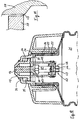
Ein in den Fig. 6 bis 11 dargestellter, gleichfalls als Flasche ausgebildeter Behälter 21 für flüssigen oder pastenförmigen Inhalt ist mit einem Hals 22 versehen, an dessen Außenffläche ein Aufschraubgewinde 3 für eine Verschlußkappe o.dgl. angeordnet ist. Mittels einer mit Innengewinde versehenen Überwurfkappe 24, die auf den Behälterhals 22 aufgeschraubt ist, wird eine Verschlußkappe 25 mit innerem Ende, das als nach außen stehender Ringflansch 26 ausgebildet ist, ggf. unter Zwischenlage einer Dichtung 27, gegen den oberen Rand 28 des Behälterhalses 22 festgehalten. Die Verschlußkappe 25 setzt gewissermaßen den Behälterhals 22 fort.A shown in FIGS. 6 to 11, also designed as a
Im Bereich des Flansches 26 und der Dichtung 27 der Verschlußkappe 25 ist eine Halterung 29 für ein zentral angeordnetes Füllstück 30 ausgebildet und befestigt. Diese Halterung 29 besteht aus einem äußeren Ring 31, von dem einzelne Speichen nach innen ragen, an denen das Füllstück 30, nach oben ragend, festsitzt. Diese ganze Anordnung kann einstückig aus Kunststoff geformt sein.In the area of the
Das Füllstück 30 ist als zylindrischer Körper ausgebildet, der in seinem obersten Bereich eine zentrale Öffnung in der Verschlußkappe 25 überragt und dort zweckmäßig als Konus 33 mit einer Durchmesserverengung ausgebildet ist.The
Innerhalb der Verschlußkappe 25 ist eine Düse 34 verschieblich geführt. Diese Düse 34 besteht aus einem Rohrabschnitt, der an seinem inneren Ende mit einem nach außen stehenden Flansch 35 versehen ist. Dieser Flansch 35 liegt mit seiner Außenfläche an der Innenfläche der Verschlußkappe 25 an und dient als Führung für die Düse 34. Weiterhin ist an der Verschlußkappe 25 am äußeren Ende ein nach innen gerichteter Flansch 36 ausgebildet, der mit seiner Innenfläche gegen die Außenfläche des rohrförmigen Teils der Düse 34 anliegt und diese ebenfalls führt. In dem zwischen den beiden Flanschen 35 und 36 gebildeten Hohlraum mit ringförmigem Querschnitt ist eine Druckfeder 37 angeordnet, die als Schraubenfeder ausgebildet, einerseits von innen gegen den Flansch 36 und andererseits gegen den Flansch 35 anliegt. Diese Druckfeder 37 hält die Düse 34 in der in der Fig. 6 dargestellten Verschlußstellung.Within the
Diese Düse ist an ihrem äußeren Ende als Hohlkonus 38 ausgebildet mit einer zentralen Öffnung 39. Zwischen der Innenfläche des Hohlkonus 38 und der flächig anliegenden Außenfläche der konusförmigen Ausbildung 33 im äußeren Ende des Füllstückes 30 bildet sich in geschlossenem Zustand der Düse ein fester und dichter Verschluß. Der freie Innendurchmesser der Düse 34 ist wesentlich größer als der Außendurchmesser des Füllstükkes 30, so daß innerhalb der Düse 34 ein weiter freier Raum entsteht, der das Füllstück 30 umgibt.This nozzle is formed at its outer end as a
Die Druckfeder 37 ist hinsichtlich ihrer Federcharakteristik derart ausgebildet, daß sie die Düse 34 mit gut schließender Dichtung gegen das Füllstück 10 hält, bei einem Druck auf den Inhalt des Behälters 21 jedoch nachgibt, so daß die Düse 34 gegenüber dem festsitzenden Füllstück 30 geführt innerhalb der Verschlußkappe 25 mittels der Flansche 35 und 36 nach außen verschiebt und damit die Düsenöffnung 39 freigibt, so daß die Stellung entsprechend der Fig. 7 erreicht ist. Der Behälterinhalt strömt dann um das Füllstück 30 herum, innerhalb des Raumes zwischen Füllstück und der Düse zur Öffnung 39. Aufgrund der konisch zusammengezogenen Ausformung 38 der Düse 34, die nunmehr oberhalb des oberen konischen Endes 33 des Füllstückes 30 liegt, wird der ausgedrückte Behälterinhalt in diesem Bereich zusammengedrückt und zu einem kompakten Strang geformt, bevor er die Düsenöffnung 39 verlassen kann. Je nach Stärke des Druckes auf den Behälterinhalt wird die Feder 37 mehr oder weniger stark zusammengedrückt und damit die Entfernung der Düsenöffnung 39 von dem äußeren Ende 33 des Füllstückes 30 entfernt, so daß der Durchtrittsquerschnitt zwischen dem oberen Düsenende und dem Füllstück vergrößert oder verkleinert ist und dementsprechend auch eine größere oder kleinere Menge vom Behälterinhalt zwischen dem äußeren Ende 33 des Füllstückes 30 und dem äußeren, als Hohlkonus 38 ausgebildeten Ende der Düse 34 zur Düsenöffnung 39 hindurch treten kann, um dort als kompakter gleichmäßig geformter Strang auszutreten.The
Um bei Nichtgebrauch, Transport und Lagerung ein Öffnen des Verschlußes wirksam zu verhindern, ist ein Verschlußdeckel 40 vorgesehen, der das obere Ende der Verschlußkappe 25 übergreift und dort angeklipst oder aufgeschraubt ist. Der Verschlußdeckel 30 legt sich mit seiner Innenfläche fest gegen die Außenfläche der Düse 34 und des Füllstückes 30, so daß die Düse 34 sich nicht von dem Füllstück 30 abheben und damit die Öffnung 39 freigeben kann.In order to effectively prevent the closure from opening when not in use, during transport and storage, a
Ein weiteres Ausführungsbeispiel ist in den Fig. 8 bis 10 dargestellt, wobei für gleiche Teile gleiche Bezugszeichen gelten. Nach diesem Ausführungsbeispiel ist der Halterungsring 31 für das Füllstück 30 mit einem Halter 41 für die Stab- oder Blattfeder 42 versehen, die in Form einesW geformt ist und in den Hals 22 des Behälters 21 hineinragt. Die Düse 34 ist mit Ansätzen 43 versehen, die bis unterhalb des Füllstückes 30 in den Behälterhals 22 hineinragen und an ihrem Ende mit einem querverlaufenden Verbindungsstück 44 den Scheitel 45 des inneren Winkels 46 der W-förmigen Feder 42 untergreifen. Die äußeren langen Schenkel 47 der W-förmigen Feder verlaufen im Schließzustand des Verschlusses etwa parallel zu der Wandung des Behälterhalses 2, wie dies aus Fig. 8 zu erkennen ist. Die W-förmige Feder 22 ist in diesem Zustand leicht gespannt, um den Verschluß geschlossen zu halten. Bei einem Druck auf den Behälterinhalt gibt die W-förmige Feder nach und es stellt sich der Zustand entsprechend der Fig. 9 ein. Die Düse 34 wird in ihrer Führung 35,36 gegenüber dem Füllstück 30 nach außen verschoben und gibt die Öffnung 39 frei, wobei die Feder 42 durch Verbiegen ihrer langen Schenkel 47 und ihres inneren Winkels 46 stärker gespannt wird. Bei Nachlassen des Druckes auf den Behälterinhalt zieht die Feder 42 die Düse 34 in ihrer Führung wieder gegen das Füllstück zurück, bis die Öffnung 39 geschlossen ist. Sämtliche weiteren Funktionen entsprechen der vorstehend, in Zusammenhang mit dem Ausführungsbeispiel nach den Fig. 6 und 7, gegebenen Beschreibung.Another exemplary embodiment is shown in FIGS. 8 to 10, the same reference numerals being used for the same parts. According to this embodiment, the
In Fig. 11 ist ein stark vergrößerter Teilausschnitt von Fig. 6 oder 8 dargestellt. Zwischen dem Flansch 35 an dem inneren Ende der Düse 34 und seiner Gegenfläche, der Führungsfläche auf der Innenseite der Verschlußkappe 25 ist eine an die Außenseite des Flansches angeformte Dichtungslippe 49 angeordnet. Dadurch wird verhindert, daß der Behälterinhalt in die Düsenführung gelangen und damit die Düsenbewegung beeinträchtigen könnte.FIG. 11 shows a greatly enlarged partial section of FIG. 6 or 8. Between the
Der Verschluß nach der Erfindung ist insbesondere hinsichtlich der Anordnung der Feder derart ausgebildet, daß er eine zusammenhängende Einheit bildet. Er ist daher einerseits einfach herstellbar, andererseits in erheblich vorteilhafter Weise gegenüber den bisher bekannten Verschlüssen leicht montierbar bzw. an jedem Behälter mit genormtem Schraubhals auch nachträglich noch anbringbar oder austauschbar ohne jegliche Veränderung oder besondere Eingriffe an dem Behälter.The closure according to the invention is designed in particular with regard to the arrangement of the spring such that it forms a coherent unit. On the one hand, it is therefore easy to manufacture, on the other hand, in a considerably advantageous manner compared to the previously known closures, it is easy to assemble or can be retrofitted or exchanged on any container with a standardized screw neck without any changes or special interventions on the container.
Bei dem in den Fig. 12 bis 14 gezeigten Ausführungsbeispiel ist auf den Hals 51 des Behälters 52 ein Deckel 53 aufgesetzt, der mit einem nach außen stehenden ringförmigen Flansch 54 auf der Oberkante des Halses 51 aufsitzt, ggf. mit einer Zwischenlage in Form einer Dichtung. Der Deckel 53 wird festgehalten von einer Überwurfkappe 55, die mit einem Schraubgewinde 56 auf das Außen an dem Hals 51 angeordnete Gewinde aufgeschraubt ist, wobei die Überwurfkappe 55 mit einem nach innen ragenden kreisförmigen Vorsprung 57 versehen ist, der den Flansch 54 übergreift. Durch Aufschrauben der Überwurfkappe 55 kann also der Deckel 53 fest dichtend und sicher auf den Hals 51 des Behälters 52 aufgebracht werden.In the exemplary embodiment shown in FIGS. 12 to 14, a
Diese gesamte Anordnung kann anstelle eines üblichen, den Behälter verschließenden Schraubdeckels verwendet und gegen diesen Schraubdeckel ausgetauscht werden, so daß jeder Behälter mit Normschraubdeckel mit diesem Verschluß versehen werden kann.This entire arrangement can be used instead of a conventional screw cap closing the container and can be exchanged for this screw cover, so that each container with a standard screw cover can be provided with this closure.
Der mittlere Bereich des Deckels 53 ist mit einer beispielsweise rechteckig begrenzten Öffnung 58 versehen, an deren Äußenrändern Klappen 59 mit Scharnieren 60 angelenkt sind. Die Klappen 59 sind gegenständig, so daß sie beim Öffnen zwischen ihren gegeneinanderliegenden Kanten 61 einen Öffnungsschlitz freigeben, durch den der Behälterinhalt austreten kann. Die Öffnung 58 ist in ihrer Mitte mit einem balkenförmigen Auflager 62 versehen, auf dem die gegeneinanderstehenden Außenkanten 61 der Klappen 59 in geschlossenem Zustand dichtend aufliegen. Dazu können diese Außenkanten 61 derart ausgebildet sein, daß sie mit einem Winkelprofil 63 das balkenförmige Auflager 62 in geschlossenem Zustand auf der Oberseite und an den beiden Seitenflächen überdecken.The central region of the
Die Gesamtanordnung ist vorzugsweise derart ausgebildet, daß sämtliche der vorbeschriebenen Einzelteile aus Kunststoff bestehen und zusammenhängend in einer Form gespritzt sind, wobei die Scharniere 60 als Filmscharniere ausgebildet sind.The overall arrangement is preferably designed in such a way that all of the above-described individual parts consist of plastic and are injection molded together in a mold, the
Nahe der beiden Seitenkanten der Klappen 59 sind in den Behälterhals 51 hineinragende Arme angeformt und zwar zweckmäßig einstückig und aus gleichem Material bestehend wie die Klappen 59, wobei dieses Material aufgrund der Querschnittausbildung der Arme 64 biegsam bzw. federelastisch ist. In ihrem oberen Teil sind die Arme 64 mit Verbreiterungen 65 versehen, die untere den beiden Seiten der Klappen 59 nach unten ragen und gegen die Seiten der Öffnungen 58 in dem Deckel 53 anliegen, so daß bei aufschwenkenden Klappen 59 der Behälterinhalt nicht nach den Seiten hin austreten kann, sondern zur Mitte hin ausschließlich durch den sich zwischen den beiden Klappen 59 bildenden Schlitz gelenkt wird. An ihrem unteren Ende sind die Arme 64 der Klappen 59 miteinander durch einen Quersteg 66 verbunden.Arms protruding into the
Eine Blattfeder 67 ist unterhalb des Deckels 53 angeordnet. Die Blattfeder 67 ist mit ihren freien Enden 68 in einem ringförmigen Teil 69 verankert, der zwischen den Flanschen 54 an dem Deckel und der Begrenzung der Öffnung 58 in dem Deckel 53, diesen auf seiner Innenseite umgibt. Die Blattfeder 67 ist geformt wie ein großes W mit langen hochstehenden Außenschenkeln 70 und einem inneren kurzen Winkel 71, der im Scheitel 72 mit den beiden Armen 64 verbunden ist, und zwar in der Weise, daß er den die Arme 64 verbindenen Stab 66 übergreift.A
Bei der Darstellung in Fig. 12 ist die W-förmige Feder in weitgehend entspanntem Zustand. Auch die Arme 64 befinden sich in ihrem Normalzustand und die Klappen 59 des Verschlusses sind geschlossen. Die W-förmige Feder 67 hat jedoch noch eine Vorspannung, so daß sie insbesondere in ihrem mittleren Bereich mit dem hochstehenden inneren Winkel 72 auf die Verbindung 66 zwischen den beiden Armen 64 wirkt, diese nach unten zieht und damit die Klappen 59 in Schließstellung hält.
Die Kraft der Feder 67 ist derart abgestimmt, daß bei einem nicht zu starken Druck auf den Behälterinhalt, also bei einem Zusammendrücken des Behälters, der dann im Behälterinnern wirkende Druck auf die Klappen 59 öffnend wirkt, indem die Rückstellkraft der Feder 67 überwunden wird. Die Klappen 59 öffnen sich und es stellt sich die Stellung entsprechend der Fig. 13 ein, in der zwischen den beiden Klappen 59 ein Öffnungsschlitz entsteht, aus dem der Behälterinhalt in einem kompakten, im wesentlichen rechteckig begrenzten Strang austritt. Anhängig von dem Druck der auf den Behälter ausgeübt wird, wird die Rückstellkraft der Feder 67 mehr oder weniger stark überwunden, so daß sich die Klappen 59 mehr oder weniger weit öffnen und dem entsprechend dem zwischen ihnen entstehende Schlitz größer oder kleiner ist. In dieser Weise läßt sich durch entsprechenden Druck auf den Behälter der austrende Behälterinhalt bzw. die Stärke des aus dem Behälter durch den Schlitz zwischen den Klappen 59 austretenden Inhaltes sehr genau dosieren.In the illustration in FIG. 12, the W-shaped spring is in a largely relaxed state. The
The force of the
Wird kein Druck mehr auf den Behälter 52 ausgeübt, schließen sich die Klappen 59 unter der Wirkung der Rückstellkraft der Feder 67. Der aus dem Behälter ausgetretene kompakte Strang des Behälterinhalts wird durch die sich schließenden Klappen sauber abgetrennt und die Klappen drücken einen letzten verbleibenden Rest des ausgetretenen Behälterinhalts wieder in den Behälter zurück aufgrund ihrer Schließbewegung. Gegenüber dem balkenförmigen Auflager 62 und aufgrund ihrer besonderen Ausformung mit dem nach innen eingenommenen Winkelprofil 63, das mit seinem senkrechten Schenkel gegenüber dem balkenförmigen Auflager 62 eine Abspreifbewegung nach unten erzeugt.If pressure is no longer exerted on the
Zum sicheren Verschließen, beispielsweise bei längerem Nichtgebrauch oder Transport, kann eine zusätzliche Sicherung verwendet werden, und zwar eine Überwurfkappe, die hier nicht dargestellt ist, die sich mit einem mittleren Teil flach auf die beiden Klappen 59 von außen und oben auflegt und mit einem nach unten stehenden Rand an der Klappe 55 fest angeklipst oder auf diese fest aufgeschraubt wird. Es ist auch möglich, anstelle dieser zusätzlichen Überwurfkappe eine Verschlußkappe zu verwenden, die ähnlich ausgebildet ist wie die Kappe 55 und gegen diese ausgetauscht wird, wobei die hier ebenfalls nicht dargestellte Verschlußkappe zwischen dem nach innen ragenden Vorsprung 57 einstückig fortgeführt ist, so daß dieser mittlere Teil sich auf die Außenseiten der beiden Klappen 59 beim Aufschrauben auf das Gewinde 56 fest dichtend und verschließend auflegt.
Der Verschluß ist insbesondere hinsichtlich der Anordnung der Feder derart ausgebildet, daß er eine zusammenhängende Einheit bildet.For secure closing, for example when not in use for a long time or during transport, an additional securing device can be used, namely a cap, which is not shown here, which lies flat on the two
The closure is designed in particular with regard to the arrangement of the spring such that it forms a coherent unit.
Claims (11)
dadurch gekennzeichnet, daß das Deckelteil (5) aus einem Material hoher Elastizität besteht und mit einem Tragkörper (4) fest verbunden ist, der aus einem Material geringer Elastizität gebildet und am Hals des Behälters (1) bzw. am Verschluß (2) im übrigen angeschlossen ist.Closure for containers with liquid or pasty contents, with a cover part arranged on the front side, which opens when the contents of the container are squeezed out and then closes automatically,
characterized in that the cover part (5) consists of a material of high elasticity and is firmly connected to a supporting body (4) which is formed from a material of low elasticity and on the neck of the container (1) or on the closure (2) in the rest connected.
Applications Claiming Priority (6)
| Application Number | Priority Date | Filing Date | Title |
|---|---|---|---|
| DE19934316145 DE4316145A1 (en) | 1993-05-14 | 1993-05-14 | Bottle or tube consisting of an elastic material |
| DE4316145 | 1993-05-14 | ||
| DE9311617U | 1993-08-05 | ||
| DE9311617U DE9311617U1 (en) | 1993-08-05 | 1993-08-05 | Closure for containers with liquid or pasty contents |
| DE9311684U | 1993-08-05 | ||
| DE9311684U DE9311684U1 (en) | 1993-08-05 | 1993-08-05 | Closure for containers with liquid or pasty contents |
Publications (3)
| Publication Number | Publication Date |
|---|---|
| EP0624526A2 true EP0624526A2 (en) | 1994-11-17 |
| EP0624526A3 EP0624526A3 (en) | 1995-11-02 |
| EP0624526B1 EP0624526B1 (en) | 1998-09-16 |
Family
ID=27205083
Family Applications (1)
| Application Number | Title | Priority Date | Filing Date |
|---|---|---|---|
| EP94107271A Expired - Lifetime EP0624526B1 (en) | 1993-05-14 | 1994-05-10 | Container for liquid or pasty contents |
Country Status (5)
| Country | Link |
|---|---|
| EP (1) | EP0624526B1 (en) |
| AT (1) | ATE171138T1 (en) |
| DE (1) | DE59406908D1 (en) |
| DK (1) | DK0624526T3 (en) |
| ES (1) | ES2121112T3 (en) |
Cited By (4)
| Publication number | Priority date | Publication date | Assignee | Title |
|---|---|---|---|---|
| US5927566A (en) * | 1996-07-11 | 1999-07-27 | Aptargroup, Inc. | One-piece dispensing system and method for making same |
| GB2424871B (en) * | 2005-04-04 | 2009-01-28 | Garry Platt | Tamper-resistant bottle closure |
| JP2010131370A (en) * | 2008-10-15 | 2010-06-17 | Rexam Pharma La Verpilliere | Liquid distribution device including sealing element movable under effect of pressure from user |
| WO2011127610A1 (en) * | 2010-04-12 | 2011-10-20 | Hoffmann Neopac Ag | One-way valve for discharge regulation in tubes, tube with such a one-way valve and method for manufacturing such a one-way valve |
Citations (10)
| Publication number | Priority date | Publication date | Assignee | Title |
|---|---|---|---|---|
| US1911616A (en) * | 1933-05-30 | Lttdwig gsttber | ||
| US2657829A (en) * | 1950-08-17 | 1953-11-03 | Lila M Walch | Collapsible tube closure openable by pressure of the contents |
| US3165242A (en) * | 1962-04-10 | 1965-01-12 | County Lab Ltd | Containers for viscous liquids |
| DE1246531B (en) * | 1962-01-02 | 1967-08-03 | Karl Walter Eberspaecher | Automatic closure for tubes and similar containers |
| GB1107403A (en) * | 1964-05-11 | 1968-03-27 | Robinson E S & A Ltd | Plastic tubes for dispensing pastey or liquid substances |
| DE2314896A1 (en) * | 1973-03-26 | 1974-10-10 | Kalkkuhl Astrid | AUTOMATIC LOCKING FOR CRUSH TUBES |
| DE2609310A1 (en) * | 1975-03-10 | 1976-09-23 | Product Form Ag | Self-sealing closure for tubes or bottles - has slits and hinged lips which open or close on application or release of pressure |
| DE3531783A1 (en) * | 1985-09-06 | 1987-03-19 | Helmut Budjin | Closure for deformable tubes |
| DE9307083U1 (en) * | 1993-05-11 | 1993-07-22 | Linneweber, Wolfgang, 4800 Bielefeld, De | |
| DE9307325U1 (en) * | 1993-05-14 | 1993-08-19 | Wolff Ernst | Bottle or tube made of an elastic material |
-
1994
- 1994-05-10 EP EP94107271A patent/EP0624526B1/en not_active Expired - Lifetime
- 1994-05-10 DE DE59406908T patent/DE59406908D1/en not_active Expired - Fee Related
- 1994-05-10 ES ES94107271T patent/ES2121112T3/en not_active Expired - Lifetime
- 1994-05-10 AT AT94107271T patent/ATE171138T1/en not_active IP Right Cessation
- 1994-05-10 DK DK94107271T patent/DK0624526T3/en active
Patent Citations (10)
| Publication number | Priority date | Publication date | Assignee | Title |
|---|---|---|---|---|
| US1911616A (en) * | 1933-05-30 | Lttdwig gsttber | ||
| US2657829A (en) * | 1950-08-17 | 1953-11-03 | Lila M Walch | Collapsible tube closure openable by pressure of the contents |
| DE1246531B (en) * | 1962-01-02 | 1967-08-03 | Karl Walter Eberspaecher | Automatic closure for tubes and similar containers |
| US3165242A (en) * | 1962-04-10 | 1965-01-12 | County Lab Ltd | Containers for viscous liquids |
| GB1107403A (en) * | 1964-05-11 | 1968-03-27 | Robinson E S & A Ltd | Plastic tubes for dispensing pastey or liquid substances |
| DE2314896A1 (en) * | 1973-03-26 | 1974-10-10 | Kalkkuhl Astrid | AUTOMATIC LOCKING FOR CRUSH TUBES |
| DE2609310A1 (en) * | 1975-03-10 | 1976-09-23 | Product Form Ag | Self-sealing closure for tubes or bottles - has slits and hinged lips which open or close on application or release of pressure |
| DE3531783A1 (en) * | 1985-09-06 | 1987-03-19 | Helmut Budjin | Closure for deformable tubes |
| DE9307083U1 (en) * | 1993-05-11 | 1993-07-22 | Linneweber, Wolfgang, 4800 Bielefeld, De | |
| DE9307325U1 (en) * | 1993-05-14 | 1993-08-19 | Wolff Ernst | Bottle or tube made of an elastic material |
Cited By (7)
| Publication number | Priority date | Publication date | Assignee | Title |
|---|---|---|---|---|
| US5927566A (en) * | 1996-07-11 | 1999-07-27 | Aptargroup, Inc. | One-piece dispensing system and method for making same |
| US6112951A (en) * | 1996-07-11 | 2000-09-05 | Aptargroup, Inc. | One-piece dispensing system and method for making same |
| GB2424871B (en) * | 2005-04-04 | 2009-01-28 | Garry Platt | Tamper-resistant bottle closure |
| JP2010131370A (en) * | 2008-10-15 | 2010-06-17 | Rexam Pharma La Verpilliere | Liquid distribution device including sealing element movable under effect of pressure from user |
| US8794490B2 (en) | 2008-10-15 | 2014-08-05 | Rexam Healthcare La Verpilliere | Liquid dispensing device equipped with a sealing component moveable under the effect of pressure by a user |
| WO2011127610A1 (en) * | 2010-04-12 | 2011-10-20 | Hoffmann Neopac Ag | One-way valve for discharge regulation in tubes, tube with such a one-way valve and method for manufacturing such a one-way valve |
| US8740023B2 (en) | 2010-04-12 | 2014-06-03 | Hoffmann Neopac Ag | One-way valve for discharge regulation in tubes, tube with such a one-way valve and method for manufacturing such a one-way valve |
Also Published As
| Publication number | Publication date |
|---|---|
| ATE171138T1 (en) | 1998-10-15 |
| DK0624526T3 (en) | 1999-06-14 |
| ES2121112T3 (en) | 1998-11-16 |
| DE59406908D1 (en) | 1998-10-22 |
| EP0624526A3 (en) | 1995-11-02 |
| EP0624526B1 (en) | 1998-09-16 |
Similar Documents
| Publication | Publication Date | Title |
|---|---|---|
| DE60214806T2 (en) | Tube provided with a valve | |
| EP1427647B1 (en) | Dispensing closure for a container that holds pourable material | |
| EP3164338B1 (en) | Pouring closure for the spout of a canister or any container for controlled multi-side pouring | |
| EP0727191A2 (en) | Container for storing and dispensing dental paste | |
| EP0048421A1 (en) | Dispenser | |
| EP0473994A2 (en) | Squeeze-bottle with internal bag | |
| DE2515095A1 (en) | SELF-CLOSING LOCK | |
| DE2646027A1 (en) | DISPENSER WITH APPLICATION BALL | |
| DE2931283C2 (en) | One-way valve for bottles | |
| DE2711591A1 (en) | CONTAINERS FOR DISPENSING LIQUIDS | |
| DE3305898A1 (en) | Fluid dispenser | |
| EP0624526A2 (en) | Closure for container with liquid or pasty contents | |
| DE3432253A1 (en) | Dispenser for liquid or pasty substances | |
| EP0287015A1 (en) | Spray can | |
| EP0087562B1 (en) | Dispenser for fluid, viscous or powdered products | |
| DE2904290A1 (en) | LOCKING ARRANGEMENT | |
| DE3347843A1 (en) | Multi-component cartridge | |
| EP0392208B1 (en) | Valve for a container for dispensing paste-like or viscous materials, in the form of a tube or bottle | |
| EP0221362B1 (en) | Dispenser for viscous materials | |
| DE3829356A1 (en) | Self-closing container closure | |
| DE4406162A1 (en) | Self closing cap for dispenser of viscous material | |
| DE2158680A1 (en) | LOCK FOR RESERVOIRS | |
| DE3111995A1 (en) | Container with dispensing head for viscous substances | |
| EP2431294B1 (en) | Rotary closure for cosmetic containers | |
| DE8217859U1 (en) | Dispenser for pasty products |
Legal Events
| Date | Code | Title | Description |
|---|---|---|---|
| PUAI | Public reference made under article 153(3) epc to a published international application that has entered the european phase |
Free format text: ORIGINAL CODE: 0009012 |
|
| AK | Designated contracting states |
Kind code of ref document: A2 Designated state(s): AT BE CH DE DK ES FR GB GR IE IT LI LU NL PT SE |
|
| PUAL | Search report despatched |
Free format text: ORIGINAL CODE: 0009013 |
|
| AK | Designated contracting states |
Kind code of ref document: A3 Designated state(s): AT BE CH DE DK ES FR GB GR IE IT LI LU MC NL PT SE |
|
| 17P | Request for examination filed |
Effective date: 19960308 |
|
| 17Q | First examination report despatched |
Effective date: 19961127 |
|
| GRAG | Despatch of communication of intention to grant |
Free format text: ORIGINAL CODE: EPIDOS AGRA |
|
| GRAG | Despatch of communication of intention to grant |
Free format text: ORIGINAL CODE: EPIDOS AGRA |
|
| GRAH | Despatch of communication of intention to grant a patent |
Free format text: ORIGINAL CODE: EPIDOS IGRA |
|
| GRAH | Despatch of communication of intention to grant a patent |
Free format text: ORIGINAL CODE: EPIDOS IGRA |
|
| ITF | It: translation for a ep patent filed |
Owner name: STUDIO INGG. FISCHETTI & WEBER |
|
| RBV | Designated contracting states (corrected) |
Designated state(s): AT BE CH DE DK ES FR GB GR IE IT LI LU NL PT SE |
|
| GRAA | (expected) grant |
Free format text: ORIGINAL CODE: 0009210 |
|
| AK | Designated contracting states |
Kind code of ref document: B1 Designated state(s): AT BE CH DE DK ES FR GB GR IE IT LI LU NL PT SE |
|
| PG25 | Lapsed in a contracting state [announced via postgrant information from national office to epo] |
Ref country code: GR Free format text: LAPSE BECAUSE OF NON-PAYMENT OF DUE FEES Effective date: 19980916 |
|
| REF | Corresponds to: |
Ref document number: 171138 Country of ref document: AT Date of ref document: 19981015 Kind code of ref document: T |
|
| REG | Reference to a national code |
Ref country code: CH Ref legal event code: NV Representative=s name: ISLER & PEDRAZZINI AG Ref country code: CH Ref legal event code: EP |
|
| REF | Corresponds to: |
Ref document number: 59406908 Country of ref document: DE Date of ref document: 19981022 |
|
| REG | Reference to a national code |
Ref country code: ES Ref legal event code: FG2A Ref document number: 2121112 Country of ref document: ES Kind code of ref document: T3 |
|
| GBT | Gb: translation of ep patent filed (gb section 77(6)(a)/1977) |
Effective date: 19981029 |
|
| REG | Reference to a national code |
Ref country code: IE Ref legal event code: FG4D Free format text: GERMAN |
|
| REG | Reference to a national code |
Ref country code: PT Ref legal event code: SC4A Free format text: AVAILABILITY OF NATIONAL TRANSLATION Effective date: 19980918 |
|
| ET | Fr: translation filed | ||
| PG25 | Lapsed in a contracting state [announced via postgrant information from national office to epo] |
Ref country code: LU Free format text: LAPSE BECAUSE OF NON-PAYMENT OF DUE FEES Effective date: 19990510 Ref country code: IE Free format text: LAPSE BECAUSE OF NON-PAYMENT OF DUE FEES Effective date: 19990510 Ref country code: GB Free format text: LAPSE BECAUSE OF NON-PAYMENT OF DUE FEES Effective date: 19990510 Ref country code: DK Free format text: LAPSE BECAUSE OF NON-PAYMENT OF DUE FEES Effective date: 19990510 Ref country code: AT Free format text: LAPSE BECAUSE OF NON-PAYMENT OF DUE FEES Effective date: 19990510 |
|
| PG25 | Lapsed in a contracting state [announced via postgrant information from national office to epo] |
Ref country code: SE Free format text: LAPSE BECAUSE OF NON-PAYMENT OF DUE FEES Effective date: 19990511 Ref country code: ES Free format text: LAPSE BECAUSE OF NON-PAYMENT OF DUE FEES Effective date: 19990511 |
|
| PG25 | Lapsed in a contracting state [announced via postgrant information from national office to epo] |
Ref country code: LI Free format text: LAPSE BECAUSE OF NON-PAYMENT OF DUE FEES Effective date: 19990531 Ref country code: CH Free format text: LAPSE BECAUSE OF NON-PAYMENT OF DUE FEES Effective date: 19990531 Ref country code: BE Free format text: LAPSE BECAUSE OF NON-PAYMENT OF DUE FEES Effective date: 19990531 |
|
| REG | Reference to a national code |
Ref country code: DK Ref legal event code: T3 |
|
| PLBE | No opposition filed within time limit |
Free format text: ORIGINAL CODE: 0009261 |
|
| STAA | Information on the status of an ep patent application or granted ep patent |
Free format text: STATUS: NO OPPOSITION FILED WITHIN TIME LIMIT |
|
| 26N | No opposition filed | ||
| BERE | Be: lapsed |
Owner name: WOLFF ERNST Effective date: 19990531 |
|
| PG25 | Lapsed in a contracting state [announced via postgrant information from national office to epo] |
Ref country code: PT Free format text: LAPSE BECAUSE OF NON-PAYMENT OF DUE FEES Effective date: 19991130 |
|
| PG25 | Lapsed in a contracting state [announced via postgrant information from national office to epo] |
Ref country code: NL Free format text: LAPSE BECAUSE OF NON-PAYMENT OF DUE FEES Effective date: 19991201 |
|
| GBPC | Gb: european patent ceased through non-payment of renewal fee |
Effective date: 19990510 |
|
| REG | Reference to a national code |
Ref country code: CH Ref legal event code: PL |
|
| EUG | Se: european patent has lapsed |
Ref document number: 94107271.2 |
|
| PG25 | Lapsed in a contracting state [announced via postgrant information from national office to epo] |
Ref country code: FR Free format text: LAPSE BECAUSE OF NON-PAYMENT OF DUE FEES Effective date: 20000131 |
|
| NLV4 | Nl: lapsed or anulled due to non-payment of the annual fee |
Effective date: 19991201 |
|
| PG25 | Lapsed in a contracting state [announced via postgrant information from national office to epo] |
Ref country code: DE Free format text: LAPSE BECAUSE OF NON-PAYMENT OF DUE FEES Effective date: 20000301 |
|
| REG | Reference to a national code |
Ref country code: FR Ref legal event code: ST |
|
| REG | Reference to a national code |
Ref country code: PT Ref legal event code: MM4A Free format text: LAPSE DUE TO NON-PAYMENT OF FEES Effective date: 19991130 |
|
| REG | Reference to a national code |
Ref country code: DK Ref legal event code: EBP |
|
| REG | Reference to a national code |
Ref country code: ES Ref legal event code: FD2A Effective date: 20030203 |
|
| PG25 | Lapsed in a contracting state [announced via postgrant information from national office to epo] |
Ref country code: IT Free format text: LAPSE BECAUSE OF NON-PAYMENT OF DUE FEES;WARNING: LAPSES OF ITALIAN PATENTS WITH EFFECTIVE DATE BEFORE 2007 MAY HAVE OCCURRED AT ANY TIME BEFORE 2007. THE CORRECT EFFECTIVE DATE MAY BE DIFFERENT FROM THE ONE RECORDED. Effective date: 20050510 |