EP0624524B1 - Packaging means - Google Patents
Packaging means Download PDFInfo
- Publication number
- EP0624524B1 EP0624524B1 EP94106775A EP94106775A EP0624524B1 EP 0624524 B1 EP0624524 B1 EP 0624524B1 EP 94106775 A EP94106775 A EP 94106775A EP 94106775 A EP94106775 A EP 94106775A EP 0624524 B1 EP0624524 B1 EP 0624524B1
- Authority
- EP
- European Patent Office
- Prior art keywords
- jaws
- base element
- axis
- adjusted
- article
- Prior art date
- Legal status (The legal status is an assumption and is not a legal conclusion. Google has not performed a legal analysis and makes no representation as to the accuracy of the status listed.)
- Expired - Lifetime
Links
Images


Classifications
-
- B—PERFORMING OPERATIONS; TRANSPORTING
- B65—CONVEYING; PACKING; STORING; HANDLING THIN OR FILAMENTARY MATERIAL
- B65D—CONTAINERS FOR STORAGE OR TRANSPORT OF ARTICLES OR MATERIALS, e.g. BAGS, BARRELS, BOTTLES, BOXES, CANS, CARTONS, CRATES, DRUMS, JARS, TANKS, HOPPERS, FORWARDING CONTAINERS; ACCESSORIES, CLOSURES, OR FITTINGS THEREFOR; PACKAGING ELEMENTS; PACKAGES
- B65D81/00—Containers, packaging elements, or packages, for contents presenting particular transport or storage problems, or adapted to be used for non-packaging purposes after removal of contents
- B65D81/02—Containers, packaging elements, or packages, for contents presenting particular transport or storage problems, or adapted to be used for non-packaging purposes after removal of contents specially adapted to protect contents from mechanical damage
- B65D81/05—Containers, packaging elements, or packages, for contents presenting particular transport or storage problems, or adapted to be used for non-packaging purposes after removal of contents specially adapted to protect contents from mechanical damage maintaining contents at spaced relation from package walls, or from other contents
- B65D81/053—Corner, edge or end protectors
- B65D81/055—Protectors contacting three surfaces of the packaged article, e.g. three-sided edge protectors
- B65D81/056—Protectors contacting three surfaces of the packaged article, e.g. three-sided edge protectors the surfaces being generally perpendicular to each other, e.g. three-sided corner protectors
-
- B—PERFORMING OPERATIONS; TRANSPORTING
- B65—CONVEYING; PACKING; STORING; HANDLING THIN OR FILAMENTARY MATERIAL
- B65D—CONTAINERS FOR STORAGE OR TRANSPORT OF ARTICLES OR MATERIALS, e.g. BAGS, BARRELS, BOTTLES, BOXES, CANS, CARTONS, CRATES, DRUMS, JARS, TANKS, HOPPERS, FORWARDING CONTAINERS; ACCESSORIES, CLOSURES, OR FITTINGS THEREFOR; PACKAGING ELEMENTS; PACKAGES
- B65D61/00—External frames or supports adapted to be assembled around, or applied to, articles
-
- B—PERFORMING OPERATIONS; TRANSPORTING
- B65—CONVEYING; PACKING; STORING; HANDLING THIN OR FILAMENTARY MATERIAL
- B65D—CONTAINERS FOR STORAGE OR TRANSPORT OF ARTICLES OR MATERIALS, e.g. BAGS, BARRELS, BOTTLES, BOXES, CANS, CARTONS, CRATES, DRUMS, JARS, TANKS, HOPPERS, FORWARDING CONTAINERS; ACCESSORIES, CLOSURES, OR FITTINGS THEREFOR; PACKAGING ELEMENTS; PACKAGES
- B65D2581/00—Containers, packaging elements, or packages, for contents presenting particular transport or storage problems, or adapted to be used for non-packaging purposes after removal of contents
- B65D2581/02—Containers, packaging elements, or packages, for contents presenting particular transport or storage problems, or adapted to be used for non-packaging purposes after removal of contents specially adapted to protect contents from mechanical damage
- B65D2581/05—Containers, packaging elements, or packages, for contents presenting particular transport or storage problems, or adapted to be used for non-packaging purposes after removal of contents specially adapted to protect contents from mechanical damage maintaining contents at spaced relation from package walls, or from other contents
- B65D2581/051—Details of packaging elements for maintaining contents at spaced relation from package walls, or from other contents
- B65D2581/052—Materials
- B65D2581/055—Plastic in general, e.g. foamed plastic, molded plastic, extruded plastic
-
- B—PERFORMING OPERATIONS; TRANSPORTING
- B65—CONVEYING; PACKING; STORING; HANDLING THIN OR FILAMENTARY MATERIAL
- B65D—CONTAINERS FOR STORAGE OR TRANSPORT OF ARTICLES OR MATERIALS, e.g. BAGS, BARRELS, BOTTLES, BOXES, CANS, CARTONS, CRATES, DRUMS, JARS, TANKS, HOPPERS, FORWARDING CONTAINERS; ACCESSORIES, CLOSURES, OR FITTINGS THEREFOR; PACKAGING ELEMENTS; PACKAGES
- B65D2581/00—Containers, packaging elements, or packages, for contents presenting particular transport or storage problems, or adapted to be used for non-packaging purposes after removal of contents
- B65D2581/02—Containers, packaging elements, or packages, for contents presenting particular transport or storage problems, or adapted to be used for non-packaging purposes after removal of contents specially adapted to protect contents from mechanical damage
- B65D2581/05—Containers, packaging elements, or packages, for contents presenting particular transport or storage problems, or adapted to be used for non-packaging purposes after removal of contents specially adapted to protect contents from mechanical damage maintaining contents at spaced relation from package walls, or from other contents
- B65D2581/051—Details of packaging elements for maintaining contents at spaced relation from package walls, or from other contents
- B65D2581/058—Edge or corner protectors connected to each other by separate elements
Definitions
- the present invention relates to a device for packaging objects, for example furniture parts, electrical appliances, ceramic tiles and the like.
- the known cardboard packaging is disadvantageous for the following reasons:
- the attachment of a form-fitting cardboard packaging to the article to be packaged requires that the packaging dimensions have to be specifically adapted to it, which means that in the case of a multiplicity of articles of different dimensions, a corresponding multiplicity of different packagings necessary is.
- cardboard materials can only fulfill the protective function to a limited extent, so that, in the case of sensitive packaging objects, additional materials may have to be introduced between the packaging and the object to dampen external impacts.
- the cardboard packaging can only be used as disposable packaging, which is seen as extremely disadvantageous by the environmental awareness that has recently grown significantly among customers and buyers of the packaged items.
- Document FR-A-418393 discloses an arrangement of protective jaws according to the preambles of claims 1 and 2, which are attached to an extendable base element which can be extended in a certain direction, the jaws engaging the base element such that the Jaws are also adjustable in a second direction, which is at right angles to the pull-out direction of the base element itself.
- the disadvantage of this arrangement is that a large number of individual components are necessary, which are connected by a type of rivet connection and which are difficult to operate.
- cardboard or plastic packaging is often used in cases in which the object to be transported is not to be protected against external impacts on all sides, but only in certain stacking or stop directions.
- all-round cladding is nevertheless carried out for reasons of stability, which in many cases represents an avoidable expenditure of material and costs.
- the present invention has for its object to provide a device for packaging objects of the above type, which is simple and has a stable structure, can be used for various packaging formats and can be used as reusable packaging.
- the object 11 can be formed, for example, by a stack of ceramic tiles or by an electrical device with rectangular outer shapes or the like.
- the packaging devices attached in each case above and below each comprise four jaws, of which only the front jaws 1, 3 can be seen in the schematic side view, and a basic element 6 connecting the jaws and allowing their displaceability, which is explained in more detail below.
- the packaging device consists of the jaws 1, 2, 3 and 4 and of the base element 6, which comprises the receiving part 6a and the insert plate 6b.
- the insert plate 6b is provided with the guide rails shown in FIG. 3, which are arranged laterally below the plate plane and into which the guide grooves 9 engage, which are provided on the inside of the recess formed by the receiving part 6a in the plane of the base element 6.
- the insert plate 6b is thereby slidably displaceable in a first direction (pull-out direction, arrow A) relative to the receiving part 6a, the limits of the displaceability being given on the one hand by the stop of the insert plate 6b on the receiving part 6a and on the other hand by stability considerations in the respective packaging.
- the jaws 1 to 4 shown in plan view each consist of three mutually perpendicular, rectangular surface sections, of which, when the jaws are attached to the base element 6, one surface section (1a to 4a) in the plane of the base element 6 and the other two surface sections (1b to 4b, 1c to 4c) are arranged perpendicular to the holder for the object to be packed.
- the jaws 1 to 4 are arranged at the corners of the base element 6. They are each provided with a guide groove 5, which are in engagement with corresponding stop screws 7 of the base element 6 and are provided with lateral guide grooves (not shown), which guide the side guide rails 8 (partly shown in dashed lines) in the plane of the base element 6. take up.
- the jaws 1 - 4 can be moved along the guide grooves 5 in a second direction (arrow B), which is perpendicular to the direction of extraction in the plane of the base element 6. 2, the jaw 4 is shown in a position displaced relative to the base element 6.
- FIG. 3 shows an exploded sectional view along the line III-III in FIG. 2, in which, for reasons of clarity, the parts forming the basic element 6 are shown separately and enlarged.
- the sectional view shows how the receiving part 6a and the push-in plate 6b engage in one another, the stepped groove-rail combination shown ensuring a pronounced stability of the base element 6.
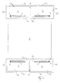
- FIG. 4 shows a top view of the exterior of the packaging device according to the invention.
- the jaws 1 to 4 are in the pushed together position relative to the base element 6.
- the base element 6 is completely pushed together, so that only the receiving part 6a can be seen from the outside.
- the surface sections 1 a to 4 a which encompass the base element 6 on its outside, are each provided with an edge profile 13 in the form of a circumferential projection which can be engaged with a corresponding recess 14 on the upper edges of the respective other surface elements of the jaws 1-4.
- This enables the packaging to be easily and safely stacked after use and returned to the manufacturer of the packaged item.
- the outer sides of the jaws 1 to 4 with a pattern which is formed by honeycombs, knobs or the like in order to dampen impacts.
- the elastic deformation of knobs on the outside of the cheeks can absorb mechanical impacts similar to the function of bumpers.
- the packaging device is used in such a way that the object to be packaged (e.g. on the conveyor belt) is placed on the base element 6 by an operator or by an appropriate automatic device, whereupon the jaws 1 to 4 in the direction of the arrows A, B are pushed towards the object until it is positively surrounded in its edge areas.
- a packaging device is attached in the same way on the top of the object and the overall structure with a suitable fasteners fixed.
- a fastening means can be formed by a tensioning band 12 or by an adhesive strip, rubber bands, shrink films or the like.
- Such locking means can, for. B. are formed by a sawtooth pattern on the contacting surfaces of the jaws 1 to 4 and the base member 6, the surface grid prevents displacement of the jaws relative to the base member, as long as the engagement between the two z. B. is loosened by mechanical means.
- This approach can, for. B. caused by a manual bracing between the mutually fixed parts.
- a corresponding locking can also be used for the mutual displaceability of the components 6a, 6b of the basic element 6. It can also be used as a locking means, for. B. lateral tensioning straps are provided which connect the jaws to each other.
- the packaging device according to the invention is advantageously produced from plastic by injection molding.
- the advantages of the packaging device according to the invention are that it can be adapted to various shapes of the cuboid objects to be packed, that it is suitable as reusable packaging and that it is permanently dimensionally stable and impact-resistant.
Abstract
Description
Die vorliegende Erfindung betrifft eine Vorrichtung zur Verpackung von Gegenständen, beispielsweise von Möbelteilen, Elektrogeräten, Keramikfliesen und dgl., deren äußere Gestalt im wesentlichen quaderförmig ist.The present invention relates to a device for packaging objects, for example furniture parts, electrical appliances, ceramic tiles and the like. The outer shape of which is essentially cuboid.
Die Verpackung von Gegenständen der o. g. Art erfolgt häufig, insbesondere wenn diese verhältnismäßig voluminös sind, durch eine formschlüssige Einschachtelung der Gegenstände mit Kartonmaterial unmittelbar nach deren Herstellung. Eine derartige Kartoneinschachtelung besitzt in erster Linie eine Schutzfunktion und wird darüberhinaus für Informationszwecke genutzt.The packaging of objects of the above Kind often occurs, especially if they are relatively voluminous, through a form-fitting nesting of the objects with cardboard material immediately after their manufacture. Such a carton box primarily has a protective function and is also used for information purposes.
Die bekannten Kartonverpackungen sind aus den folgenden Gründen nachteilig:
Die Anbringung einer formgerechten Kartonverpackung an dem zu verpackenden Gegenstand erfordert, daß die Verpackungsmaße spezifisch an diesen angepaßt sein müssen, wodurch bei einer Vielzahl von zu verpackenden Gegenständen verschiedener Ausmaße eine entsprechende Vielzahl verschiedener Verpackungen notwendig ist. Außerdem können Kartonmaterialien die Schutzfunktion nur in begrenztem Maße erfüllen, so daß gegebenenfalls bei empfindlichen Verpackungsgegenständen weitere Materialen zwischen der Verpackung und dem Gegenstand zum Abdämpfen äußerer Schläge eingebracht werden müssen. Schließlich sind die Kartonverpackungen aufgrund ihrer geringen Stabilität lediglich als Einwegverpackungen nutzbar, was durch das in jüngster Zeit entscheidend gewachsene Umweltbewußtsein bei den Abnehmern bzw. Käufern der verpackten Gegenstände als äußerst nachteilig aufgefaßt wird.The known cardboard packaging is disadvantageous for the following reasons:
The attachment of a form-fitting cardboard packaging to the article to be packaged requires that the packaging dimensions have to be specifically adapted to it, which means that in the case of a multiplicity of articles of different dimensions, a corresponding multiplicity of different packagings necessary is. In addition, cardboard materials can only fulfill the protective function to a limited extent, so that, in the case of sensitive packaging objects, additional materials may have to be introduced between the packaging and the object to dampen external impacts. Finally, due to their low stability, the cardboard packaging can only be used as disposable packaging, which is seen as extremely disadvantageous by the environmental awareness that has recently grown significantly among customers and buyers of the packaged items.
Dokument FR-A-418393 offenbart eine Anordnung von Schutzbacken gemäß den Oberbegriffen der Ansprüche 1 und 2, die an einem ausziehbaren Grundelement angebracht sind, das sich in eine bestimmte Richtung ausziehen läßt, wobei die Backen derart mit dem Grundelement in Eingriff stehen, daß die Backen auch in einer zweiten Richtung verstellbar sind, die im rechten Winkel zur Ausziehrichtung des Grundelementes selbst liegt. Der Nachteil dieser Anordnung besteht darin, daß eine Vielzahl von einzelnen Bauteilen notwendig ist, die über eine Art von Nietverbindungen verbunden sind, und die sich schlecht bedienen lassen.Document FR-A-418393 discloses an arrangement of protective jaws according to the preambles of
Darüber hinaus werden Karton- oder Kunststoffverpackungen häufig auch in solchen Fällen verwendet, in denen der zu transportierende Gegenstand nicht allseitig, sondern lediglich in bestimmten Stapel- oder Anschlagrichtungen gegen äußere Stöße zu schützen ist. Bei derartigen Anwendungen wird bei dem Einsatz der herkömmlichen Karton- oder Kunststoffverpackungen aus Stabilitätsgründen dennoch eine allseitige Umkleidung durchgeführt, was einen in vielen Fällen vermeidbaren Material- und Kostenaufwand darstellt.In addition, cardboard or plastic packaging is often used in cases in which the object to be transported is not to be protected against external impacts on all sides, but only in certain stacking or stop directions. In such applications, when using the conventional cardboard or plastic packaging, all-round cladding is nevertheless carried out for reasons of stability, which in many cases represents an avoidable expenditure of material and costs.
Demgegenüber liegt der vorliegenden Erfindung die Aufgabe zugrunde, eine Vorrichtung zur Verpackung von Gegenständen der oben genannten Art bereitzustellen, die einen einfachen und stabilen Aufbau besitzt, für verschiedene Verpackungsformate verwendbar und als Mehrwegverpackung einsetzbar ist.In contrast, the present invention has for its object to provide a device for packaging objects of the above type, which is simple and has a stable structure, can be used for various packaging formats and can be used as reusable packaging.
Diese Aufgabe wird durch eine Verpackungsvorrichtung mit den in den Schutzansprüchen 1 und 2 enthaltenen Merkmalen gelöst. Vorteilhafte Ausführungsformen der erfindungsgemäßen Verpackungsvorrichtung ergeben sich aus den Unteransprüchen.This object is achieved by a packaging device with the features contained in the
Im folgenden wird ein Ausführungsbeispiel der erfindungsgemäßen Verpackungsvorrichtung anhand der beigefügten Zeichnungen im einzelnen beschrieben. Es zeigen:
- Fig. 1 eine schematische Seitenansicht eines verpackten Gegenstandes;
- Fig. 2 eine Draufsicht auf das Innere der erfindungsgemäßen Verpackungsvorrichtung; und
- Fig. 3 eine auseinandergezogene Schnittdarstellung entlang der Linie III-III in Fig. 2;
- Fig. 4 eine Draufsicht auf eine Außenseite der erfindungsgemäßen Verpackungsvorrichtung.
- Figure 1 is a schematic side view of a packaged item.
- 2 shows a plan view of the interior of the packaging device according to the invention; and
- Fig. 3 is an exploded sectional view taken along the line III-III in Fig. 2;
- Fig. 4 is a plan view of an outside of the packaging device according to the invention.
In Fig 1 ist die Verpackung des Gegenstandes 11 unter Verwendung von erfindungsgemäßen Verpackungsvorrichtungen dargestellt, die in Stapelrichtung jeweils ober- und unterhalb des Gegenstandes 11 angeordnet und mit diesem mittels des Spannbandes 12 verbunden sind. Der Gegenstand 11 kann zum Beispiel durch einen Stapel von Keramikfliesen oder durch ein Elektrogerät mit quaderförmigen Außenformen oder dgl. gebildet werden. Die jeweils oben und unten angebrachten Verpackungsvorrichtungen umfassen jeweils vier Backen, von denen in der schematischen Seitenansicht lediglich die vorderen Backen 1, 3 zu sehen sind, sowie ein die Backen verbindendes und deren weiter unten im einzelnen erläuterte Verschiebbarkeit erlaubendes Grundelement 6.1 shows the packaging of the
In Fig. 2 ist das Innere der erfindungsgemäßen Verpackungsvorrichtung in Draufsicht dargestellt, wobei sich diese in einem teilweise auseinandergezogenen Zustand befindet. Die Verpackungsvorrichtung besteht aus den Backen 1, 2, 3 und 4 sowie aus dem Grundelement 6, das das Aufnahmeteil 6a und die Einschubplatte 6b umfaßt. Die Einschubplatte 6b ist mit dem in Fig. 3 gezeigten Führungsschienen versehen, die seitlich unterhalb der Plattenebene geordnet sind und in die die Führungsnuten 9 eingreifen, die an der Innenseite der durch das Aufnahmeteil 6a gebildeten Ausnehmung in der Ebene des Grundelementes 6 vorgesehen sind. Die Einschubplatte 6b ist dadurch gegenüber dem Aufnahmeteil 6a in einer ersten Richtung (Ausziehrichtung, Pfeil A) gleitend verschiebbar, wobei die Grenzen der Verschiebbarkeit einerseits durch den Anschlag der Einschubplatte 6b an dem Aufnahmeteil 6a und andererseits durch Stabilitätserwägungen bei der jeweiligen Verpackung gegeben sind.2 shows the inside of the packaging device according to the invention in plan view, the latter being in a partially pulled-apart state. The packaging device consists of the
Die in Draufsicht dargestellten Backen 1 bis 4 bestehen jeweils aus drei zueinander senkrecht stehenden, rechtwinkligen Flächenabschnitten, von denen bei Anbringung der Backen an dem Grundelement 6 jeweils ein Flächenabschnitt (1a bis 4a) in der Ebene des Grundelementes 6 und die übrigen beiden Flächenabschnitte (1b bis 4b, 1c bis 4c) zu dieser senkrecht zur Halterung des zu verpackenden Gegenstandes angeordnet sind. Die Backen 1 bis 4 sind an den Ecken des Grundelementes 6 angeordnet. Sie sind jeweils mit einer Führungsnut 5, die in Eingriff mit entsprechenden Anschlagschrauben 7 des Grundelementes 6 stehen und mit (nicht gezeigten) seitlichen Führungsnuten versehen, die die in der Ebene des Grundelementes 6 angebrachten, seitlichen Führungsschienen 8 (z. T. gestrichelt gezeichnet) aufnehmen. Die Backen 1 - 4 sind entlang der Führungsnuten 5 in eine zweite Richtung verschiebbar (Pfeil B), die zu der Ausziehrichtung in der Ebene des Grundelementes 6 senkrecht verläuft. In Fig. 2 ist die Backe 4 in einer gegenüber dem Grundelement 6 verschobenen Position gezeigt.The jaws 1 to 4 shown in plan view each consist of three mutually perpendicular, rectangular surface sections, of which, when the jaws are attached to the
Fig. 3 zeigt eine auseinandergezogene Schnittansicht entlang der Linie III-III in Fig. 2, bei der aus Gründen der Übersichtlichkeit die das Grundelement 6 bildenden Anteile getrennt und vergrößert dargestellt sind. Der Schnittansicht ist zu entnehmen, wie das Aufnahmeteil 6a und die Einschubplatte 6b ineinandergreifen, wobei die dargestellte, abgestufte Nut-Schiene-Kombination für eine ausgeprägte Stabilität des Grundelementes 6 sorgt.FIG. 3 shows an exploded sectional view along the line III-III in FIG. 2, in which, for reasons of clarity, the parts forming the
In Fig. 4 ist eine Draufsicht auf das Äußere der erfindungsgemäßen Verpackungsvorrichtung dargestellt. Die Backen 1 bis 4 befinden sich in gegenüber dem Grundelement 6 zusammengeschobener Stellung. Ebenso ist das Grundelement 6 vollständig zusammengeschoben, so daß nur das Aufnahmeteil 6a nach außen erkennbar ist.4 shows a top view of the exterior of the packaging device according to the invention. The jaws 1 to 4 are in the pushed together position relative to the
Die Flächenabschnitte 1a bis 4a, die das Grundelement 6 auf seiner Außenseite umgreifen, sind jeweils mit einer Randprofilierung 13 in Form eines umlaufenden Vorsprunges versehen, der paßfähig mit einer entsprechenden Ausnehmung 14 an den Oberkanten der jeweils übrigen Flächenelemente der Backen 1-4 eingriffsfähig sind. Damit wird ermöglicht, daß die Verpackungen nach Verwendung einfach und sicher gestapelt und zum Hersteller des verpackten Gegenstandes zurückgeführt werden können. Ersatzweise ist es auch möglich, die Verpackungsvorrichtungen mit Stapelabständen an den Backen zu versehen, um eine Stapelbarkeit der verpackten Gegenstände zu ermöglichen.The surface sections 1 a to 4 a, which encompass the
Zur Erhöhung der Schlagfestigkeit der erfindungsgemäßen Verpackungsvorrichtung ist es möglich, die Außenseiten der Backen 1 bis 4 mit einem Muster zu versehen, das durch Waben, Noppen oder dgl. gebildet wird, um damit Aufschläge zu dämpfen. So kann die elastische Verformung von Noppen auf den Backenaußenseiten analog zur Funktion von Stoßstangen mechanische Aufschläge absorbieren.To increase the impact resistance of the packaging device according to the invention, it is possible to provide the outer sides of the jaws 1 to 4 with a pattern which is formed by honeycombs, knobs or the like in order to dampen impacts. The elastic deformation of knobs on the outside of the cheeks can absorb mechanical impacts similar to the function of bumpers.
Die Verwendung der Verpackungsvorrichtung erfolgt derart, daß unmittelbar bei Herstellung des zu verpackenden Gegenstandes (z. B. am Fließband) dieser von einem Bediener oder durch eine entsprechende automatische Einrichtung auf das Grundelement 6 aufgesetzt wird, woraufhin die Backen 1 bis 4 in Richtung der Pfeile A, B an den Gegenstand herangeschoben werden, bis dieser in seinen Randbereichen formschlüssig umgeben ist. Entsprechend der Darstellung in Fig. 1 wird in gleicher Weise auf der Oberseite des Gegenstandes eine Verpackungsvorrichtung formgerecht angebracht und der Gesamtaufbau mit einem geeigneten Befestigungsmittel fixiert. Ein derartiges Befestigungsmittel kann durch ein Spannband 12 oder durch einen Klebestreifen, Gummibänder, Schrumpffolien oder dgl. gebildet werden.The packaging device is used in such a way that the object to be packaged (e.g. on the conveyor belt) is placed on the
Es ist möglich, in den Figuren nicht dargestellte Arretierungsmittel zu vorzusehen, mit denen die in die entsprechend formgerechte Position geschobenen Backen 1 bis 4 fixiert werden können. Derartige Arretierungsmittel können z. B. durch eine Sägezahnmusterung auf den sich berührenden Flächen der Backen 1 bis 4 und des Grundelementes 6 gebildet werden, deren Oberflächenraster eine Verschiebung der Backen gegenüber dem Grundelement verhindert, solange der Eingriff zwischen beiden nicht z. B. mit mechanischen Mitteln gelockert wird. Dieses Anstücken kann z. B. durch eine manuelle Verspannung zwischen den aneinander fixierten Teile bewirkt werden. Eine entsprechende Arretierung ist auch für die gegenseitige Verschiebbarkeit der Bestandteile 6a, 6b des Grundelementes 6 einsetzbar. Es können als Arretierungsmittel aber auch z. B. seitliche Spannbänder vorgesehen sein, die die Backen miteinander verbinden.It is possible to provide locking means, not shown in the figures, with which the jaws 1 to 4 which have been pushed into the correspondingly correct position can be fixed. Such locking means can, for. B. are formed by a sawtooth pattern on the contacting surfaces of the jaws 1 to 4 and the
Die erfindungsgemäße Verpackungsvorrichtung wird vorteilhafterweise aus Kunststoff im Spritzgußverfahren hergestellt.The packaging device according to the invention is advantageously produced from plastic by injection molding.
Gegenüber den Darstellungen der erfindungsgemäßen Verpackungsvorrichtung sind die folgenden Modifikationen denkbar:
Es ist möglich, das Grundelement 6 durch ein im Mittelbereich offenes Rahmenelement zu ersetzen, wobei jeweils ineinander greifende Rahmenteile mit entsprechenden Führungsnuten und - schienen versehen sind. Weiterhin ist es möglich, das dargestellte Grundelement mit Ausnehmungen zu versehen, um Material zu sparen, oder auf das Grundelement eine zusätzliche Profilierung aufzubringen, mit der die Stabilität der Anordnung erhöht wird. Außerdem ist im Unterschied zur Darstellung in Fig. 1 möglich, die Verpackungsvorrichtungen nicht in Stapelrichtung, sondern seitlich an dem Gegenstand anzubringen.The following modifications are conceivable compared to the illustrations of the packaging device according to the invention:
It is possible to replace the
Die Vorteile der erfindungsgemäßen Verpackungsvorrichtung bestehen darin, daß diese an vielfältige Formen der zu verpackenden quaderförmigen Gegenstände angepaßt werden kann, daß sie sich als Mehrwegverpackung eignet und daß sie dauerhaft formstabil und schlagfest ist.The advantages of the packaging device according to the invention are that it can be adapted to various shapes of the cuboid objects to be packed, that it is suitable as reusable packaging and that it is permanently dimensionally stable and impact-resistant.
Claims (6)
- Packing device for articles such as, for example, furniture parts, electrical appliances, ceramic tiles and the like, having a base element (6) with four jaws (1, 2, 3, 4) which are disposed at the corners and of which opposite pairs of jaws (1, 2; 3, 4) can be adjusted in relation to one another along a first axis and the jaws of each pair of jaws can be adjusted along a second axis perpendicular thereto, wherein the jaws can be fixed in the desired settings in accordance with the dimensions of the article to be packed and wherein the jaws have guide elements (5) which are in engagement in such a way with the base element (6), which can be drawn out in the direction of the first axis, that the jaws can be adjusted in the direction of the second axis, characterized in that the base element is formed by a two-part baseplate (6) which consists of a receiving part (6a) with a recess in which guide grooves (9) are disposed, and of an insertion plate (6b) with lateral guide rails (10), which insertion plate can be inserted in the receiving part (6a).
- Packing device for articles such as, for example, electrical appliances, ceramic tiles, furniture parts and the like, having a base element (6) with four jaws (1, 2, 3, 4) which are disposed at the corners and of which opposite pairs of jaws (1, 2; 3, 4) can be adjusted in relation to one another along a first axis and the jaws of each pair of jaws can be adjusted along a second axis perpendicular thereto, wherein the jaws can be fixed in the desired settings in accordance with the dimensions of the article to be packed and wherein the jaws have guide elements (5) which are in engagement in such a way with the base element (6), which can be drawn out in the direction of the first axis, that the jaws can be adjusted in the direction of the second axis, characterized in that the base element (6) is formed by a two-part frame consisting of an outer and an inner frame part, which parts are in engagement with one another via guide rails and can be displaced in relation to one another in the direction of drawing out.
- Packing device according to Claim 1 or 2, characterized in that the jaws and/or the base element are constructed in an impact-absorbing manner and are preferably provided with a profiling in the form of a pattern of knobs, inner honeycomb structure or the like.
- Packing device according to Claim 2 or 3, characterized in that the adjusting arrangements of the jaws and the base frame parts are provided with latching and/or locking arrangements for securing the adjustment positions of the device on the article to be packed and the latching and/or locking arrangements can be unlatched or unlocked manually for the purpose of unpacking the article.
- Packing device according to Claim 1 or 3, characterized in that the jaws (1 to 4) are provided, on surfaces that touch the base element (6), with a profiling, preferably after the manner of a saw-tooth or pawl profile, which is in engagement with a corresponding profiling or latch on the base element (6) for fixing the position of the jaws, and the receiving part (6a) and the insertion plate (6b) are designed so as to be capable of latching into one another.
- Packing device according to one of Claims 1 or 3, characterized in that the said device can be connected with a fastening means (12) to the article to be packed.
Applications Claiming Priority (2)
| Application Number | Priority Date | Filing Date | Title |
|---|---|---|---|
| DE9307169U DE9307169U1 (en) | 1993-05-11 | 1993-05-11 | |
| DE9307169U | 1993-05-11 |
Publications (2)
| Publication Number | Publication Date |
|---|---|
| EP0624524A1 EP0624524A1 (en) | 1994-11-17 |
| EP0624524B1 true EP0624524B1 (en) | 1995-11-15 |
Family
ID=6893160
Family Applications (1)
| Application Number | Title | Priority Date | Filing Date |
|---|---|---|---|
| EP94106775A Expired - Lifetime EP0624524B1 (en) | 1993-05-11 | 1994-04-29 | Packaging means |
Country Status (5)
| Country | Link |
|---|---|
| EP (1) | EP0624524B1 (en) |
| AT (1) | ATE130265T1 (en) |
| DE (2) | DE9307169U1 (en) |
| DK (1) | DK0624524T3 (en) |
| ES (1) | ES2079985T3 (en) |
Families Citing this family (3)
| Publication number | Priority date | Publication date | Assignee | Title |
|---|---|---|---|---|
| DE29606009U1 (en) * | 1996-03-20 | 1996-06-05 | Romwell Guenther Schilling Gmb | Packing pad |
| CN105035557B (en) * | 2015-08-06 | 2017-03-22 | 京东方科技集团股份有限公司 | Substrate cartridge |
| EP4249393A3 (en) * | 2022-03-25 | 2023-12-20 | Movopack S.r.l. | Reusable packaging for a household appliance and method for reusing said packaging |
Family Cites Families (7)
| Publication number | Priority date | Publication date | Assignee | Title |
|---|---|---|---|---|
| FR418393A (en) * | 1910-07-20 | 1910-12-07 | Rosa Bauer | Expandable shipping box |
| GB614079A (en) * | 1946-07-04 | 1948-12-09 | William Kinnell Petrie | A new or improved expansible case or container |
| DD108705A1 (en) * | 1973-11-19 | 1974-10-05 | ||
| DE2646908A1 (en) * | 1976-10-18 | 1978-04-20 | Bellaplast Gmbh | Protective piece goods packing - has profiled strips round contents and between padding components fitted over corners |
| DE8714373U1 (en) * | 1987-10-29 | 1987-12-23 | Ostma Maschinenbau Gmbh, 5352 Zuelpich, De | |
| GB2246767A (en) * | 1990-07-25 | 1992-02-12 | Digital Equipment Int | Protective packaging |
| DE9310386U1 (en) * | 1992-07-13 | 1993-08-26 | Vaillant Joh Gmbh & Co | Packaging for devices |
-
1993
- 1993-05-11 DE DE9307169U patent/DE9307169U1/de not_active Expired - Lifetime
-
1994
- 1994-04-29 ES ES94106775T patent/ES2079985T3/en not_active Expired - Lifetime
- 1994-04-29 AT AT94106775T patent/ATE130265T1/en not_active IP Right Cessation
- 1994-04-29 EP EP94106775A patent/EP0624524B1/en not_active Expired - Lifetime
- 1994-04-29 DK DK94106775.3T patent/DK0624524T3/en active
- 1994-04-29 DE DE59400044T patent/DE59400044D1/en not_active Expired - Fee Related
Also Published As
| Publication number | Publication date |
|---|---|
| ES2079985T3 (en) | 1996-01-16 |
| ATE130265T1 (en) | 1995-12-15 |
| EP0624524A1 (en) | 1994-11-17 |
| DK0624524T3 (en) | 1995-12-18 |
| DE59400044D1 (en) | 1995-12-21 |
| DE9307169U1 (en) | 1993-07-15 |
Similar Documents
| Publication | Publication Date | Title |
|---|---|---|
| DE3124391C2 (en) | suitcase | |
| DE19603657B4 (en) | Safety accessories for vehicles | |
| EP2925195A1 (en) | Removal safeguard for knife blocks | |
| DE3635866A1 (en) | DISK HOLDER | |
| DE102018106981A1 (en) | Container system with frame element | |
| EP0624524B1 (en) | Packaging means | |
| EP0499152A1 (en) | Folder, or the like | |
| EP0143299A2 (en) | Corner or edge protector | |
| EP3078612A1 (en) | Device for holding a refuse bag | |
| DE4232155C2 (en) | Shock protective bracket | |
| DE19527692C2 (en) | Device for receiving a panel element | |
| DE8009110U1 (en) | ARMREST FOR A VEHICLE SEAT | |
| EP1777171A2 (en) | Package for electronic parts, in particular notebooks | |
| CH705900A2 (en) | Package insert, package with a package insert and method for manufacturing a package insert. | |
| EP0257322A1 (en) | Device for attaching a hinge to fixing means | |
| EP1035031A2 (en) | Supporting device for drilling tool | |
| DE2258250A1 (en) | ARCHIVE FOLDER FOR OLD FILES OF WRITTEN MATERIAL | |
| DE4103018A1 (en) | Holder for object esp. lamp to be packed - is of strip material bent along folding lines running across and mutually parallel to give vertical rear part and base part extending to front | |
| DE4309110C1 (en) | Packaging element for shirts - has clamps for securing position of edge section of short bottom folded around narrow support plate | |
| DE2923927A1 (en) | Flat microscope slide container - includes body with rectangular blind holes and guide grooves in opposite sides | |
| EP0064187B1 (en) | Device for holding and arranging a plurality of different objects, particularly tools | |
| DE102021130532A1 (en) | Secure box, in particular a folding box, and a leaflet therefor | |
| DE2911217A1 (en) | Storage holder for video tape cassettes of different sizes - has two relatively sliding parts lockable in various positions | |
| EP0691094A1 (en) | Display-case for jewels | |
| AT408747B (en) | Pack for data carriers in the form of flat discs |
Legal Events
| Date | Code | Title | Description |
|---|---|---|---|
| PUAI | Public reference made under article 153(3) epc to a published international application that has entered the european phase |
Free format text: ORIGINAL CODE: 0009012 |
|
| AK | Designated contracting states |
Kind code of ref document: A1 Designated state(s): AT BE CH DE DK ES FR IT LI NL SE |
|
| 17P | Request for examination filed |
Effective date: 19941220 |
|
| 17Q | First examination report despatched |
Effective date: 19950124 |
|
| GRAA | (expected) grant |
Free format text: ORIGINAL CODE: 0009210 |
|
| AK | Designated contracting states |
Kind code of ref document: B1 Designated state(s): AT BE CH DE DK ES FR IT LI NL SE |
|
| REF | Corresponds to: |
Ref document number: 130265 Country of ref document: AT Date of ref document: 19951215 Kind code of ref document: T |
|
| REG | Reference to a national code |
Ref country code: DK Ref legal event code: T3 |
|
| REF | Corresponds to: |
Ref document number: 59400044 Country of ref document: DE Date of ref document: 19951221 |
|
| ET | Fr: translation filed | ||
| REG | Reference to a national code |
Ref country code: ES Ref legal event code: FG2A Ref document number: 2079985 Country of ref document: ES Kind code of ref document: T3 |
|
| ITF | It: translation for a ep patent filed |
Owner name: PROPRIA PROTEZIONE PROPR. IND. |
|
| REG | Reference to a national code |
Ref country code: CH Ref legal event code: NV Representative=s name: R. A. EGLI & CO. PATENTANWAELTE |
|
| PGFP | Annual fee paid to national office [announced via postgrant information from national office to epo] |
Ref country code: SE Payment date: 19960419 Year of fee payment: 3 |
|
| PGFP | Annual fee paid to national office [announced via postgrant information from national office to epo] |
Ref country code: DK Payment date: 19960422 Year of fee payment: 3 |
|
| PLBE | No opposition filed within time limit |
Free format text: ORIGINAL CODE: 0009261 |
|
| STAA | Information on the status of an ep patent application or granted ep patent |
Free format text: STATUS: NO OPPOSITION FILED WITHIN TIME LIMIT |
|
| 26N | No opposition filed | ||
| PGFP | Annual fee paid to national office [announced via postgrant information from national office to epo] |
Ref country code: FR Payment date: 19970417 Year of fee payment: 4 |
|
| PGFP | Annual fee paid to national office [announced via postgrant information from national office to epo] |
Ref country code: BE Payment date: 19970422 Year of fee payment: 4 |
|
| PGFP | Annual fee paid to national office [announced via postgrant information from national office to epo] |
Ref country code: AT Payment date: 19970423 Year of fee payment: 4 |
|
| PG25 | Lapsed in a contracting state [announced via postgrant information from national office to epo] |
Ref country code: DK Effective date: 19970429 |
|
| PGFP | Annual fee paid to national office [announced via postgrant information from national office to epo] |
Ref country code: CH Payment date: 19970429 Year of fee payment: 4 |
|
| REG | Reference to a national code |
Ref country code: DK Ref legal event code: EBP |
|
| PG25 | Lapsed in a contracting state [announced via postgrant information from national office to epo] |
Ref country code: SE Effective date: 19970430 |
|
| PGFP | Annual fee paid to national office [announced via postgrant information from national office to epo] |
Ref country code: ES Payment date: 19970430 Year of fee payment: 4 |
|
| PGFP | Annual fee paid to national office [announced via postgrant information from national office to epo] |
Ref country code: DE Payment date: 19970625 Year of fee payment: 4 |
|
| EUG | Se: european patent has lapsed |
Ref document number: 94106775.3 |
|
| PG25 | Lapsed in a contracting state [announced via postgrant information from national office to epo] |
Ref country code: AT Free format text: LAPSE BECAUSE OF NON-PAYMENT OF DUE FEES Effective date: 19980429 |
|
| PG25 | Lapsed in a contracting state [announced via postgrant information from national office to epo] |
Ref country code: LI Free format text: LAPSE BECAUSE OF NON-PAYMENT OF DUE FEES Effective date: 19980430 Ref country code: FR Free format text: THE PATENT HAS BEEN ANNULLED BY A DECISION OF A NATIONAL AUTHORITY Effective date: 19980430 Ref country code: ES Free format text: LAPSE BECAUSE OF EXPIRATION OF PROTECTION Effective date: 19980430 Ref country code: CH Free format text: LAPSE BECAUSE OF NON-PAYMENT OF DUE FEES Effective date: 19980430 Ref country code: BE Free format text: LAPSE BECAUSE OF NON-PAYMENT OF DUE FEES Effective date: 19980430 |
|
| BERE | Be: lapsed |
Owner name: S.A. SCHOELLER-PLAST Effective date: 19980430 |
|
| PG25 | Lapsed in a contracting state [announced via postgrant information from national office to epo] |
Ref country code: NL Free format text: LAPSE BECAUSE OF NON-PAYMENT OF DUE FEES Effective date: 19981101 |
|
| REG | Reference to a national code |
Ref country code: CH Ref legal event code: PL |
|
| NLV4 | Nl: lapsed or anulled due to non-payment of the annual fee |
Effective date: 19981101 |
|
| PG25 | Lapsed in a contracting state [announced via postgrant information from national office to epo] |
Ref country code: DE Free format text: LAPSE BECAUSE OF NON-PAYMENT OF DUE FEES Effective date: 19990202 |
|
| REG | Reference to a national code |
Ref country code: FR Ref legal event code: ST |
|
| REG | Reference to a national code |
Ref country code: ES Ref legal event code: FD2A Effective date: 20000201 |
|
| PG25 | Lapsed in a contracting state [announced via postgrant information from national office to epo] |
Ref country code: IT Free format text: LAPSE BECAUSE OF NON-PAYMENT OF DUE FEES Effective date: 20050429 |